Abstract
Polarization imaging finds applications in many areas, such as photoelasticity, ellipsometry, and biomedical imaging. A compact, snapshot, and high-efficiency imaging polarimeter is highly desirable for many applications. Here, based on a single multifunctional geometric phase optical element (GPOE), a new method is proposed for high-efficiency snapshot imaging polarimetry. With tailored spatially varying orientation of each anisotropic unit cell, the GPOE works highly efficiently as both a spin sorter and a half-wave plate, enabling snapshot retrieving of a full Stokes vector of incident light. The designed GPOE is implemented in the form of liquid crystal fabricated with a photo-alignment technology, and its application in imaging polarimetry is experimentally demonstrated by retrieving full Stokes parameters of a cylinder vector beam. This method can also work in the form of plasmonic or dielectric metasurfaces, enabling ultra-compact polarization detection systems by monolithic integration with other devices such as metalenses.1. INTRODUCTION
Polarization is an intrinsic and important property of light. Polarization-resolved detection allows acquiring lots of information on the investigated objects, such as refractive index, shapes, texture, and birefringence/charity (circular dichroism). Therefore, polarization-resolved imaging plays important roles not only in conventional applications such as photoelasticity, ophthalmology, ellipsometry, and bio-imaging, but also in recently developed areas such as generalized laser beam profiling [1,2], quantum state tomography [3], and optical communication [4]. Recently, to investigate ultrafast polarization-related optical phenomena and interactions [5,6], the snapshot polarimetric imaging system has become an urgent requirement. Although many efforts have been devoted to designing such a snapshot imaging polarimeter [7–9], most existing imaging polarimeters suffer more or less from limitations in terms of completeness of polarization information, efficiency, field of view, angular resolution, compactness, etc. Gori proposed a method for polarimetry using polarization gratings [10], where spin-dependent light response was used to retrieve a circular Stokes parameter efficiently and robustly. Since then, many efforts [11–14] have been devoted to investigating high-efficiency polarimetry based on polarization gratings. However, due to the limited functions realized by polarization gratings, high-efficiency snapshot full Stokes polarimeters and imaging polarimeters with a compact setup are still big challenges.
In recent years, there has been ever-growing interest in compact polarimetry based on a geometric phase optical element (GPOE) and metasurface [15–22], due to the recent advances in design methods for beam manipulation [19,23,24] and development of fabrication technologies [25–28]. However, most of the demonstrations employ either segmented or interleaved design strategies. Due to the inherent limitations of these strategies [19] (e.g., small angular resolution, low optical efficiency, and deleterious crosstalk noise), it is generally difficult to generalize the existing demonstrations to imaging polarimetry. To date, only a few works on metasurface-based imaging polarimetry have been reported [29,30], with limited spatial resolution due to the segmented design. Opposite to the segmented and interleaved designs, harmonic response designs possess merits of both high efficiency and high angular resolution [19]. To the best of our knowledge, imaging polarimetry based on a harmonic response metasurface or GPOE has not yet been demonstrated.
Here, we propose and experimentally demonstrate a novel multifunctional GPOE for high-efficiency snapshot imaging polarimetry. The GPOE is designed to be a harmonic response with an algorithm [24] that controls both diffraction amplitude and phase of light beams, and is capable of working as a spin sorter and a half-wave plate (HWP) simultaneously. We show that such a multifunctional GPOE enables snapshot full Stokes parameters retrieved by measuring far-field intensities of light beams emerging from the GPOE. Due to the harmonic response of the designed GPOE [19], the proposed imaging polarimeter shows advantages of high efficiency and high angular resolution, both of which are vital for polarimetric imaging systems. Furthermore, since geometric phase is solely determined by geometrical orientation of unit cells, the designed GPOE is broadband, robust, simply fabricated, and scalable to other electromagnetic spectra. The operation principle of the GPOE is illustrated analytically in detail, followed by numerical demonstration. To experimentally demonstrate GPOE-based imaging polarimetry, a GPOE is fabricated with photo-alignment liquid crystal (LC) technology [31,32] and used to retrieve full Stokes parameters of a cylinder vector beam [32], which has spatially varying states of polarization. The proposed GPOE imaging polarimeter is robust, passive, compact, and highly efficient, and thus could find applications in a wide variety of fields, such as photoelasticity, ophthalmology, ellipsometry, remote sensing, bio-imaging, ultra-fast light–matter interactions, nanophotonics, optical communications, and quantum optics.
Sign up for Photonics Research TOC. Get the latest issue of Photonics Research delivered right to you!Sign up now
2. DESIGN AND PRINCIPLE
We first introduce the desired functions of the GPOE. The multifunctional GPOE is essentially a periodic diffractive optical element that controls the polarization state of each diffraction order. As shown in Fig. 1(a), for an arbitrary elliptically polarized incident light, the GPOE is designed to generate four dominant diffraction orders. For the two high-diffraction orders ( orders), the GPOE works as a spin sorter, enabling spatial separation of left- and right-circular polarization (LCP and RCP) components of light, and thus achieves detection of and components of the incident light. For the two low-diffraction orders ( orders), the GPOE works as an HWP with the fast axis along the axis and therefore generates a mirrored polarization ellipse of the incident light about the axis, as shown in Fig. 1(b). We can see that 0° linear polarization components of the two ellipses are the same, while the 45° linear polarization component of the diffraction ellipse (blue dashed line) has the same value as the linear polarization component of the incident ellipse (red dashed line). Thus, we can obtain the and components of incident light by measuring the light intensities of orders transmitted through 0° and 45° linear polarizers, respectively. With the four components , , , and determined at a single snapshot, full Stokes parameters can be calculated with simple algebra calculation [20]. Finally, complete polarization imaging of incident light can be achieved by mapping full Stokes parameters of each point in the beam profile of the incident light.
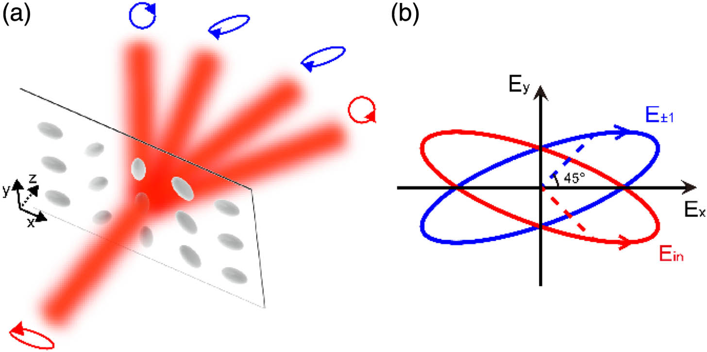
Figure 1.Schematic of operation principle of the GPOE for polarimetry. (a) The GPOE is designed to work as a spin sorter for high () and a half-wave plate for low () diffraction orders, respectively. (b) Polarization ellipses of the incident light (red) and low-order diffraction beams (blue) are mirrored with each other about the axis. Red (blue) dashed lines indicate amplitude of field components at ( at 45°) of the incident ( orders) beams.
Next, we show how to achieve the above functions with a single GPOE device. We find that such a multifunctional GPOE can be designed with an optimized scalar phase profile through controlling diffraction amplitudes and phases. To obtain the desired , a semi-analytical algorithm [24] is used to maximize diffraction efficiency with constraint conditions on complex diffraction coefficients as and (see Appendix A for the detailed optimization method). The optimized phase profile is given by , where , is the equivalent wave-vector, and is the period length.
In the following, we analyze the polarization response of GPOE with the designed phase profile and show its applications in polarimetry and polarimetric imaging.
The polarization response of the GPOE is calculated with Jones calculus under the paraxial approximation [33]. The method is simple yet instructive, and can be extended for incompletely polarized or incoherent light [11]. The GPOE can be modeled as an array of wave plates with spatially varying slow-axis orientations. A half-wave birefringence retardation is preferred to maximize diffraction efficiency [33]. The corresponding Jones matrix is where is the slow-axis orientation of each unit cell with respect to the axis. The Jones vector of each diffraction order in the far field can be calculated as where represents the Jones vector of incident light, and is the diffraction order. It is instructive to rewrite the Jones vectors of the incident and output light in the helicity basis as where and denote diffraction coefficients for LCP and RCP incident light, respectively. It can be shown from Eq. (2) that is always satisfied, due to the opposite geometric phase imposed on LCP and RCP light.
In Table 1, we give an example of calculated complex diffraction coefficients of GPOE for LCP and RCP incident light (see analytical results in Appendix A). We find that , i.e., the orders for LCP light have the same diffraction amplitude but opposite phase. This condition, combined with Eqs. (3) and (4), can be used to derive the polarization state of the orders as . Thus, for the orders, the function of the GPOE can be described by a Jones matrix in the circular polarization basis as , representing an HWP with the fast axis along the axis. The equivalent wave plate is exactly one of the desired functions of GPOE shown in Fig. 1. For the orders, Table 1 shows that , combined with Eq. (4), indicating a spin-dependent angular deflection fulfills the spin sorting function of the desired GPOE. This spin sorting property of GPOE is due to intrinsic photonics spin-orbital interaction [27,28,34,35] and has been used to retrieve and Stokes parameters [11,17,36]. In Table 1, the total diffraction efficiency (, ) is as high as 94.4% and is independent of the polarization state of incident light, enabling high-efficiency retrieving of full Stokes parameters. We notice that the efficiency can be further improved by releasing the constraint on the diffraction amplitude of high orders [37].
| Order | −3 | −1 | +1 | +3 |
| LCP DL | −0.5554 | 0.5554 | 0.5554 | 0.1374 |
| RCP DR | 0.1374 | 0.5554 | 0.5554 | −0.5554 |
Table 1. Complex Coefficients of the Four Dominated Diffraction Orders (, ) for LCP, RCP Incident Light
For an arbitrary polarized incident light, the retrieved full Stokes vector can be calculated (see Appendix B) using Eqs. (3) and (4) and detected intensities of the four diffraction orders as where are intensities of the high orders, and are intensities of the low orders transmitted through 45° and 0° linear polarizers, respectively.
3. RESULTS AND DISCUSSION
To study performance of the designed GPOE, in Figs. 2(a)–2(d), we show theoretically calculated polarization response of the above designed GPOE for incident light with LCP, RCP, 0°, and 45° linear polarization (LP), respectively. The polarization ellipses and diffraction intensities of each diffraction order through GPOE are shown in the top and middle panels of each figure, respectively. For orders in Figs. 2(a) and 2(b), the GPOE not only changes the helicity of the incident light, but also induces a helicity-dependent unidirectional diffraction pattern, and thus functions as a spin sorter. We notice that for the orders in Figs. 2(c) and 2(d), the polarization ellipses of orders are not perfectly circular due to the non-zero value of , which has been taken into account in retrieving Stokes parameters (see Appendix B). For orders, the diffraction intensities and polarization ellipses are always the same since , and the polarization ellipses are always mirrored with that of the incident light (insets of bottom panels), indicating the HWP function of the GPOE. In the bottom panels of each figure, we show light intensities at the detection plane with orders passing through 45° and 0° linear polarizers. The total optical efficiency for each incident polarization can be calculated by summing the intensities in the bottom panels of Figs. 2(a)–2(d), and the results are 63.6%, 63.6%, 79.0%, and 48.2%, respectively. The optical efficiency for completely unpolarized light is 63.6%, much higher than the efficiency of previously reported polarimeters composed of linear and circular polarizers (maximal efficiency 50%) [38,39], since only light of orders passes through polarizers with some power loss. With Eq. (5) and the intensities in the bottom panels, we can retrieve the Stokes vectors for Figs. 2(a)–2(d) as , , , and , respectively, in good agreement with the polarization states of the four incident lights.

Figure 2.Calculated intensities and polarization states of the diffraction orders (, ) through GPOE for the incident light with (a) LCP, (b) RCP, (c) 0°, and (d) 45° LP, respectively. In each subfigure, polarization ellipses and intensities are shown in top and middle panels, while the bottom panels show intensities through 0° and 45° polarizers indicated by gray circles and arrows.
Next, we show how to achieve polarization imaging with the GPOE. In Fig. 3(a), we schematically show the optical configuration for polarization imaging calculation. It is a simplified imaging system consisting of two lenses. The first lens transforms light from each point of a scene into its angular spectrum. The angular spectrum transmits through the designed GPOE and then is focused by the other lens to the image plane where order regions are covered with 45° and 0° linear polarizers (gray areas in right dotted box).
Figure 3.Numerical demonstration of imaging polarimetry based on the GPOE. (a) Schematic of the optical configuration in the calculation. The scene with six areas of different polarizations is shown in left dashed box. (b) Calculated intensity map at the image plane. (c) Retrieved Stokes parameters (left to right panels) of the light.
To show the function of the polarization imaging system, we theoretically calculated an example, where the scene is composed of six areas (gratings and spirals in left dashed box). Each area emits light with a binary intensity pattern (black for 1 and white for 0) and an unique polarization state from top to bottom, 0°, 90°, 45°, and LP, LCP and RCP, respectively. A map of the calculated intensity at the image plane is shown in Fig. 3(b). For each diffraction order, the intensity map shows a distinct pattern with a specific “missing” area, where light intensity is (nearly) zero, in agreement with the corresponding results in Fig. 2. The distinct patterns illustrate explicit polarization imaging capability of the proposed GPOE-based imaging polarimetry. In Fig. 3(c), we present retrieved full Stokes parameters S0–S3 (from left to right panels) of the incident light, by inserting the intensity map in Fig. 3(b) into Eq. (5). We find that the retrieved Stokes vectors of the six regions are , , , , , and , respectively, in good agreement with the polarization distributions of the incident scene.
To experimentally realize the GPOE device, we choose the liquid crystal (LC) material, where the designed geometric phase is encoded into in-plane orientation of anisotropic LC. To evaluate the performance of LC-based GPOE before fabrication, we performed full electromagnetic simulations with the finite-difference time-domain method (Lumerical FDTD Solutions). In the simulations, nematic LC E7 was modeled [40–43] as an in-plane uniaxial anisotropy medium with spatially varying permittivity tensors. The ordinary and extraordinary refractive indices of LC were set as and , respectively. The thickness of the LC layer fulfilled to introduce a retardation of half-wave at design wavelength . A single period (, composed of 16 unit cells) was simulated along with periodic boundary condition and normal light incidence. An anti-reflection layer with a refractive index and thickness was used to reduce reflection at the air–LC interface, resulting in transmittances as high as 98.7%, almost polarization independent. Far-field intensities were calculated by near-to-far-field projection of the electric field transmitted through the LC layer. After normalization to far-field intensity without LC, complex diffraction coefficients were obtained. In Figs. 4(a)–4(d), polarization ellipses (diffraction intensities) are shown in top (bottom) panels for the incident light of LCP, RCP, 0°, and 45° LP, respectively. The polarization ellipses are slightly different from the ideal case in Fig. 2, i.e., ellipticity for all orders in Figs. 4(a)–4(d) and low orders in Figs. 4(c) and 4(d) are not exactly zero. The deviations might be due to the slightly different transmission amplitudes (see intensities in bottom panels) introduced by large index contrast between and . The diffraction efficiency (sum of and ) for each order in Fig. 4 is almost the same as the results in Fig. 2, demonstrating the capability of LC GPOE for high-efficiency polarization measurement. The retrieved normalized Stokes vectors for the four incident polarizations are , , , and , respectively, agreeing well with the corresponding theoretical values of the incident light.
Figure 4.Polarization beam splitting of the designed LC GPOE for (a) LCP, (b) RCP, (c) 0°, and (d) 45° LP incident light, respectively. Top panels: polarization ellipses; bottom panels: diffraction intensities of (blue solid line) and (red solid line) components. Incident polarizations are shown in the insets.
The designed LC GPOE was fabricated with a dynamic micro-lithography technology [31,32]. The technology has been used to demonstrate various functional GPOEs [28,40,44,45] and is well suited for imaging applications due to high transmissivity over a broadband spectrum, large aperture, tunable retardation with an applied voltage, and high optical damage threshold [31]. One period of the fabricated GPOE consists of 64 pixels; each pixel size is about . The polarization microscope image of the fabricated GPOE is shown in the inset of Fig. 5(a). The clear aperture of the fabricated GPOE consists of , roughly , which is large enough for some applications such as microscopy and endoscopy. In addition, phase quantization into 17 levels was carried out, and had negligible influence on complex diffraction coefficients (see Fig. 7 in Appendix A).
Figure 5.(a) Optical setup for a polarimeter based on GPOE. A polarization microscope image of the fabricated LC-GPOE is shown as the inset. (b) Experimentally detected intensity maps for the incident light of LCP, RCP, 0°, and 45° linear polarization (from top to bottom). The incident polarizations are shown in the left column.
A simple optical experimental setup was built to characterize polarization response of the fabricated LC GPOE, as shown in Fig. 5(a). A polarization generator consisting of a polarizer (P), half-wave plate (HWP), and quarter-wave plate (QWP) was adopted to generate the desired incident polarization. A polarizer was placed in front of the CCD in order to measure the desired intensity components. The experimentally measured diffraction patterns are shown in Fig. 5(b) for LCP, RCP, 0°, and 45° LP incident light (from top to bottom). The measured diffraction patterns are similar to the bottom panels in Fig. 2 qualitatively. It is noted that the non-zero intensity of zero order is due to overfilling of the GPOE and slight deviation from half-wave retardation. By inserting the detected intensities of each diffraction order into Eq. (5), we obtain the Stokes vectors as , , , and . The experimental results of retrieved Stokes vectors show a trend similar to the above theoretical results but with some deviation, due mainly to fabrication imperfection, alignment, and calibration of optical components [46,47], and also polarization-sensitive Fresnel transmission due to slightly oblique incidence. To further improve the experimental results, a calibration process [38,39] that compensates all system errors is considered (see Appendix C for more results and calibration).
To experimentally demonstrate an imaging polarimeter based on the GPOE, we employed a cylinder vector beam (CVB) as incident light, which has complex amplitude and polarization distributions, and retrieved its full Stokes parameters. A CVB [48] can generally be described with a Jones vector: where is the beam intensity profile, is the azimuthal topological charge, is the azimuthal angle, and determines the polarization state on a high-order Poincaré sphere. Here, a two-order CVB was generated by transmitting LP light through a commercial vortex retarder (see Appendix D for a schematic of the experimental setup). The parameter is estimated to be from the captured intensities of different field components of the generated CVB (see Appendix D). By inserting the GPOE after the vortex retarder, we experimentally detected an intensity map of each diffraction order for the incident CVB, as shown in Fig. 6(a). For high-diffraction orders, the intensity patterns show a donut-like shape, which is reasonable, since the generated CVB is linearly polarized (thus equal circular polarization components) at each point of beam cross section [see black arrows in left panel of Fig. 6(b)]. For low orders, the intensity patterns are very similar to the and of the incident CVB (see Appendix D). The residual zero-order transmission is due to non-ideal retardation and can be eliminated with proper bias voltage. In Fig. 6(b), the theoretical Stokes parameters of an ideal CVB are shown, while in Fig. 6(c), the experimentally retrieved Stokes parameters are compared. For the S1 and S2 parameters, the petal patterns in Fig. 6(c) have almost the same shape as that in Fig. 6(b). For the parameter, the theoretical values in Fig. 6(b) are zero; however, the retrieved values in Fig. 6(c) are non-zero. The departure is due to imaging aberration for high-diffraction order, which can be seen definitely in Fig. 6(a). The imaging aberration also leads to some deviation of intensity maps () from a perfect donut shape.
Figure 6.Polarization imaging of a CVB beam. (a) Light intensities of each diffraction order captured by CCD. (b) Theoretical results of Stokes parameters of an ideal second-order CVB; arrows in the left panel indicate polarization ellipses at each position. (c) Experimental results of retrieved Stokes parameters for the generated CVB beam.
4. CONCLUSION
In conclusion, we have designed a multifunctional GPOE for high-efficiency snapshot imaging polarimetry. The designed GPOE behaves as spin sorter for high-diffraction orders and HWP for low-diffraction orders, obtained by controlling both amplitude and phase of complex diffraction coefficients. We implemented the GPOE in the form of photo-alignment nematic LC and experimentally demonstrated its polarimetric imaging capability by mapping the complex polarization distribution of a two-order CVB.
In addition, we should note that although the GPOE is designed for a high-efficiency imaging polarimeter in this article, the device could be easily modified for various applications, such as in-line nonintrusive light beam monitoring. One advantage of the GPOE is the retardation-independent functions for non-zero diffraction orders [33,49], i.e., the functions of the GPOE are determined fully by geometric orientation. When the retardation departs from half-wave, only a portion of light beams experiences geometric phase, while the other part transmits directly through GPOE without any change in normalized profiles of intensity, phase, or polarization. This peculiar property of GPOE [33] could be valuable for applications where in situ nonintrusive monitoring of light beams [50] are vital, such as real-time monitoring of laser beams and augmented reality. Thus, the GPOE device could be used for in-line nondestructive light beam monitoring by altering the effective retardation of GPOE. For the case of GPOE based on LC, the retardation can be modified by applying an appropriate voltage on the device.
As another consequence of its geometric nature, the functions of GPOE can be robust and broadband. Due to inherent diffraction angle dispersion, the GPOE could be well adopted in designing a snapshot imaging spectral polarimeter [20,21,50,51]. Alternatively, a broadband achromatic optical metasurface [52] could be designed for full-color imaging polarimetry. The design method shown here can be implemented in forms of plasmonic/dielectric metasurfaces [53] and other compact forms of GPOE [26], which have subwavelength thickness and can be fabricated with CMOS compatible techniques [53,54]. Furthermore, monolithic integration with other optical elements such as metalenses is also feasible [26,29,55,56], enabling a series of ultra-compact and mass-producible polarization detection and imaging systems.
APPENDIX A: PHASE DESIGN ALGORITHM, DIFFRACTION COEFFICIENTS, AND PHASE QUANTIZATION
To design the desired phase distribution, we follow the procedures in Ref. [24]. The least square problem shown in the following is first solved with a goal to maximize total diffraction efficiency by adjusting the optimization variable : In the above equations, is the desired phase distribution, and is the diffraction coefficients of order . We find that, through a MATLAB script, when , the goal is achieved. Next, a Lagrange multiplier is introduced, and after some simplification, and can be expressed as Finally, diffraction efficiency can be maximized under the constraints and . The maximum diffraction efficiency is found to be 92.6% when . The optimized phase distribution is shown in Fig. 7(a) as a green dashed line. In Fig. 7(b), we show the complex diffraction coefficients for the dominated order (green solid dots). As seen, the results satisfy the desired diffraction pattern and . The complex diffraction coefficients can also be calculated analytically as where and denote the complete elliptic integrals of the first and second kinds.
To facilitate the fabrication of LC GPOE, the phase profile is discretized into 17 levels, indicated by the orange dots in Fig. 7(a). The complex diffraction coefficients of the discretized phase are shown in Fig. 7(b) as orange circled pluses. As seen, the complex diffraction coefficients of the discretized phase agree well with the analytical results.
Figure 7.(a) Analytical (green solid line) and discretized (orange dots) phase profile of the designed GPOE. (b) Intensity (top panel) and phase (bottom panel) of the dominated diffraction orders (, ) for the analytical (green dots) and discretized (orange circled pluses) phase profile.
APPENDIX B: RETRIEVING THE FULL STOKES VECTOR
According to Eq. (3) in the main text, the polarization state of the orders is . The diffraction intensity of the orders can be calculated as . Considering Eq. (4) in the main text, we can obtain the following equation: which can be used to retrieve and , for the given diffraction intensities. The intensity of the component of the order is Similarly, the intensity of the component of the order is Thus, and can be retrieved, for the given and diffraction intensities. In summary, we can retrieve full Stokes parameters with measured intensities , , , and .
APPENDIX C: MORE SPIN OF STATES AND CALIBRATION
We have measured more states of polarization (SOP) and calibrated the GPOE polarimeter at 1550 nm with four photodiode detectors. In Fig. 8(a), theoretical (top panel) and experimental (bottom panel) detected intensities for linear polarization incidence of varying polarization angles are shown. As seen, the experimental intensities show similar dependence on the polarization angle to the theoretical results. However, the exact values of theoretical and experimental results show substantial discrepancy. To retrieve accurate Stokes parameters, we employ a calibration method [57].
Figure 8.(a) Theoretical (top panel) and experimental (bottom panel) detected intensities for linear polarization incidence of varying polarization angles. (b) Theoretical (lines) and retrieved (dots) Stokes parameters of SOP along the 30° latitude of Poincaré sphere. (c) Poincaré sphere representation of SOP obtained by rotating QWP while keeping HWP horizontally oriented.
The retrieved Stokes parameters can be calculated as , where is the calibrated instrumental matrix, and is the detected intensities. In Fig. 8(b), we show theoretical (lines) and retrieved (dots) Stokes parameters of SOP along the 30° latitude of the Poincaré sphere, which are obtained by simultaneously rotating HWP and QWP an angle of and , respectively. We see that the retrieved Stokes parameters agree well with the theoretical ones. In Fig. 8(c), we show theoretical and retrieved SOP on the Poincaré sphere obtained by rotating QWP while keeping HWP horizontally oriented. The maximum spherical distance between theoretical and retrieved Stokes vectors on the Poincaré sphere is around 3°. The spherical distance is calculated as , where is the discrepancy between the theoretical () and retrieved () Stokes vectors. Advanced calibration is needed to retrieve Stokes vectors that are more accurate.
APPENDIX D: BEAM PROFILE OF THE INCIDENT CVB
In Fig. 9(a), we show the optical setup for polarization imaging of the generated CVB. Here, a vortex retarder plate (WPV10-780, Thorlabs Inc.) was used to generate the two-order CVB. An HWP was used to tune the position of the generated CVB on the high-order Poincaré sphere. We measured intensities , , and of the incident CVB (without the GPOE shown in the dashed box) by rotating the polarizer before the CCD, as shown in Fig. 9(b), respectively. By measuring the azimuthal angle of maximum intensities of petals, we evaluate parameter to be . Inserting into Eq. (6), we obtain fitted theoretical intensity maps, as shown in Fig. 9(c). The fitted theoretical intensity maps agree well with the detected intensity maps.
Figure 9.(a) Optical setup for characterizing the generated CVB (without GPOE) and polarization imaging (with GPOE). (b) Detected and (c) fitted theoretical intensity maps of the generated CVB.
References
[1] T. Bauer, S. Orlov, U. Peschel, P. Banzer, G. Leuchs. Nanointerferometric amplitude and phase reconstruction of tightly focused vector beams. Nat. Photonics, 8, 23-27(2014).
[2] O. G. Rodríguez-Herrera, D. Lara, C. Dainty. Far-field polarization-based sensitivity to sub-resolution displacements of a sub-resolution scatterer in tightly focused fields. Opt. Express, 18, 5609-5628(2010).
[3] K. Wang, J. G. Titchener, S. S. Kruk, L. Xu, H.-P. Chung, M. Parry, I. I. Kravchenko, Y.-H. Chen, A. S. Solntsev, Y. S. Kivshar, D. N. Neshev, A. A. Sukhorukov. Quantum metasurface for multiphoton interference and state reconstruction. Science, 361, 1104-1108(2018).
[4] Z.-Y. Chen, L.-S. Yan, Y. Pan, L. Jiang, A.-L. Yi, W. Pan, B. Luo. Use of polarization freedom beyond polarization-division multiplexing to support high-speed and spectral-efficient data transmission. Light Sci. Appl., 6, e16207(2017).
[5] Y. Ye, J. Xiao, H. Wang, Z. Ye, H. Zhu, M. Zhao, Y. Wang, J. Zhao, X. Yin, X. Zhang. Electrical generation and control of the valley carriers in a monolayer transition metal dichalcogenide. Nat. Nanotechnol., 11, 598-602(2016).
[6] P.-C. Huang, C. Hernández-García, J.-T. Huang, P.-Y. Huang, C.-H. Lu, L. Rego, D. D. Hickstein, J. L. Ellis, A. Jaron-Becker, A. Becker, S.-D. Yang, C. G. Durfee, L. Plaja, H. C. Kapteyn, M. M. Murnane, A. H. Kung, M.-C. Chen. Polarization control of isolated high-harmonic pulses. Nat. Photonics, 12, 349-354(2018).
[7] R. M. A. Azzam. Stokes-vector and Mueller-matrix polarimetry [invited]. J. Opt. Soc. Am. A, 33, 1396-1408(2016).
[8] J. S. Tyo, D. L. Goldstein, D. B. Chenault, J. A. Shaw. Review of passive imaging polarimetry for remote sensing applications. Appl. Opt., 45, 5453-5469(2006).
[9] M. Garcia, C. Edmiston, R. Marinov, A. Vail, V. Gruev. Bio-inspired color-polarization imager for real-time in situ imaging. Optica, 4, 1263-1271(2017).
[10] F. Gori. Measuring Stokes parameters by means of a polarization grating. Opt. Lett., 24, 584-586(1999).
[11] Y. Gorodetski, G. Biener, A. Niv, V. Kleiner, E. Hasman. Space-variant polarization manipulation for far-field polarimetry by use of subwavelength dielectric gratings. Opt. Lett., 30, 2245-2247(2005).
[12] C. Oh, M. J. Escuti. Achromatic diffraction from polarization gratings with high efficiency. Opt. Lett., 33, 2287-2289(2008).
[13] M. W. Kudenov, M. J. Escuti, E. L. Dereniak, K. Oka. White-light channeled imaging polarimeter using broadband polarization gratings. Appl. Opt., 50, 2283-2293(2011).
[14] I. Moreno, J. A. Davis, K. Badham, M. M. Sánchez-López, J. E. Holland, D. M. Cottrell. Vector beam polarization state spectrum analyzer. Sci. Rep., 7, 2216(2017).
[15] S. Wei, Z. Yang, M. Zhao. Design of ultracompact polarimeters based on dielectric metasurfaces. Opt. Lett., 42, 1580-1583(2017).
[16] P. C. Wu, J.-W. Chen, C.-W. Yin, Y.-C. Lai, T. L. Chung, C. Y. Liao, B. H. Chen, K.-W. Lee, C.-J. Chuang, C.-M. Wang, D. P. Tsai. Visible metasurfaces for on-chip polarimetry. ACS Photon., 5, 2568-2573(2017).
[17] D. Wen, F. Yue, S. Kumar, Y. Ma, M. Chen, X. Ren, P. E. Kremer, B. D. Gerardot, M. R. Taghizadeh, G. S. Buller, X. Chen. Metasurface for characterization of the polarization state of light. Opt. Express, 23, 10272-10281(2015).
[18] A. Shaltout, J. Liu, A. Kildishev, V. Shalaev. Photonic spin Hall effect in gap-plasmon metasurfaces for on-chip chiroptical spectroscopy. Optica, 2, 860-863(2015).
[19] E. Maguid, I. Yulevich, D. Veksler, V. Kleiner, M. L. Brongersma, E. Hasman. Photonic spin-controlled multifunctional shared-aperture antenna array. Science, 352, 1202-1206(2016).
[20] F. Ding, A. Pors, Y. Chen, V. A. Zenin, S. I. Bozhevolnyi. Beam-size-invariant spectropolarimeters using gap-plasmon metasurfaces. ACS Photon., 4, 943-949(2017).
[21] C. W. Ting, T. Peter, R. F. Matthew, L. C. Yen, T. Wei-Yi, W. P. Ru, T. D. Ping. Integrated plasmonic metasurfaces for spectropolarimetry. Nanotechnology, 27, 224002(2016).
[22] N. A. Rubin, A. Zaidi, M. Juhl, R. P. Li, J. P. B. Mueller, R. C. Devlin, K. Leósson, F. Capasso. Polarization state generation and measurement with a single metasurface. Opt. Express, 26, 21455-21478(2018).
[23] N. Yu, P. Genevet, M. A. Kats, F. Aieta, J.-P. Tetienne, F. Capasso, Z. Gaburro. Light propagation with phase discontinuities: generalized laws of reflection and refraction. Science, 334, 333-337(2011).
[24] L. A. Romero, F. M. Dickey. Theory of optimal beam splitting by phase gratings. I. One-dimensional gratings. J. Opt. Soc. Am. A, 24, 2280-2295(2007).
[25] G. Zheng, H. Muhlenbernd, M. Kenney, G. Li, T. Zentgraf, S. Zhang. Metasurface holograms reaching 80% efficiency. Nat. Nanotechnol., 10, 308-312(2015).
[26] J. Zhou, H. Qian, G. Hu, H. Luo, S. Wen, Z. Liu. Broadband photonic spin Hall meta-lens. ACS Nano, 12, 82-88(2018).
[27] D. Lin, P. Fan, E. Hasman, M. L. Brongersma. Dielectric gradient metasurface optical elements. Science, 345, 298-302(2014).
[28] J. Kim, Y. Li, M. N. Miskiewicz, C. Oh, M. W. Kudenov, M. J. Escuti. Fabrication of ideal geometric-phase holograms with arbitrary wavefronts. Optica, 2, 958-964(2015).
[29] E. Arbabi, S. M. Kamali, A. Arbabi, A. Faraon. Full-Stokes imaging polarimetry using dielectric metasurfaces. ACS Photon., 5, 3132-3140(2018).
[30] Z. Yang, Z. Wang, Y. Wang, X. Feng, M. Zhao, Z. Wan, L. Zhu, J. Liu, Y. Huang, J. Xia, M. Wegener. Generalized Hartmann-Shack array of dielectric metalens sub-arrays for polarimetric beam profiling. Nat. Commun., 9, 4607(2018).
[31] P. Chen, B.-Y. Wei, W. Ji, S.-J. Ge, W. Hu, F. Xu, V. Chigrinov, Y.-Q. Lu. Arbitrary and reconfigurable optical vortex generation: a high-efficiency technique using director-varying liquid crystal fork gratings. Photon. Res., 3, 133-139(2015).
[32] J. Fang, Z. Xie, T. Lei, C. Min, L. Du, Z. Li, X. Yuan. Spin-dependent optical geometric transformation for cylindrical vector beam multiplexing communication. ACS Photon., 5, 3478-3484(2018).
[33] J. Tervo, J. Turunen. Paraxial-domain diffractive elements with 100% efficiency based on polarization gratings. Opt. Lett., 25, 785-786(2000).
[34] K. Y. Bliokh, F. J. Rodriguez-Fortuno, F. Nori, A. V. Zayats. Spin-orbit interactions of light. Nat. Photonics, 9, 796-808(2015).
[35] X. Ling, X. Zhou, X. Yi, W. Shu, Y. Liu, S. Chen, H. Luo, S. Wen, D. Fan. Giant photonic spin Hall effect in momentum space in a structured metamaterial with spatially varying birefringence. Light Sci. Appl., 4, e290(2015).
[36] F. J. Rodríguez-Fortuño, I. Barber-Sanz, D. Puerto, A. Griol, A. Martínez. Resolving light handedness with an on-chip silicon microdisk. ACS Photon., 1, 762-767(2014).
[37] J. Albero, I. Moreno, J. A. Davis, D. M. Cottrell, D. Sand. Generalized phase diffraction gratings with tailored intensity. Opt. Lett., 37, 4227-4229(2012).
[38] X. Zhao, A. Bermak, F. Boussaid, V. G. Chigrinov. Liquid-crystal micropolarimeter array for full Stokes polarization imaging in visible spectrum. Opt. Express, 18, 17776-17787(2010).
[39] W.-L. Hsu, G. Myhre, K. Balakrishnan, N. Brock, M. Ibn-Elhaj, S. Pau. Full-Stokes imaging polarimeter using an array of elliptical polarizer. Opt. Express, 22, 3063-3074(2014).
[40] P. Chen, S.-J. Ge, L.-L. Ma, W. Hu, V. Chigrinov, Y.-Q. Lu. Generation of equal-energy orbital angular momentum beams via photopatterned liquid crystals. Phys. Rev. Appl., 5, 044009(2016).
[41] X. Wang, B. Wang, P. J. Bos, J. E. Anderson, J. J. Pouch, F. A. Miranda. Finite-difference time-domain simulation of a liquid-crystal optical phased array. J. Opt. Soc. Am. A, 22, 346-354(2005).
[42] C. Oh, M. J. Escuti. Numerical analysis of polarization gratings using the finite-difference time-domain method. Phys. Rev. A, 76, 043815(2007).
[43] A. Alberucci, C. P. Jisha, L. Marrucci, G. Assanto. Electromagnetic confinement via spin-orbit interaction in anisotropic dielectrics. ACS Photon., 3, 2249-2254(2016).
[44] P. Chen, S.-J. Ge, W. Duan, B.-Y. Wei, G.-X. Cui, W. Hu, Y.-Q. Lu. Digitalized geometric phases for parallel optical spin and orbital angular momentum encoding. ACS Photon., 4, 1333-1338(2017).
[45] S. V. Serak, D. E. Roberts, J.-Y. Hwang, S. R. Nersisyan, N. V. Tabiryan, T. J. Bunning, D. M. Steeves, B. R. Kimball. Diffractive waveplate arrays [invited]. J. Opt. Soc. Am. B, 34, B56-B63(2017).
[46] A. De Martino, E. Garcia-Caurel, B. Laude, B. Drévillon. General methods for optimized design and calibration of Mueller polarimeters. Thin Solid Films, 455-456, 112-119(2004).
[47] E. Compain, S. Poirier, B. Drevillon. General and self-consistent method for the calibration of polarization modulators, polarimeters, and Mueller-matrix ellipsometers. Appl. Opt., 38, 3490-3502(1999).
[48] Z. Liu, Y. Liu, Y. Ke, Y. Liu, W. Shu, H. Luo, S. Wen. Generation of arbitrary vector vortex beams on hybrid-order Poincaré sphere. Photon. Res., 5, 15-21(2017).
[49] F. Yue, D. Wen, J. Xin, B. D. Gerardot, J. Li, X. Chen. Vector vortex beam generation with a single plasmonic metasurface. ACS Photon., 3, 1558-1563(2016).
[50] Q.-T. Li, F. Dong, B. Wang, W. Chu, Q. Gong, M. L. Brongersma, Y. Li. Free-space optical beam tapping with an all-silica metasurface. ACS Photon., 4, 2544-2549(2017).
[51] A. Y. Zhu, W.-T. Chen, M. Khorasaninejad, J. Oh, A. Zaidi, I. Mishra, R. C. Devlin, F. Capasso. Ultra-compact visible chiral spectrometer with meta-lenses. APL Photonics, 2, 036103(2017).
[52] S. Wang, P. C. Wu, V.-C. Su, Y.-C. Lai, C. Hung Chu, J.-W. Chen, S.-H. Lu, J. Chen, B. Xu, C.-H. Kuan, T. Li, S. Zhu, D. P. Tsai. Broadband achromatic optical metasurface devices. Nat. Commun., 8, 187(2017).
[53] P. Genevet, F. Capasso, F. Aieta, M. Khorasaninejad, R. Devlin. Recent advances in planar optics: from plasmonic to dielectric metasurfaces. Optica, 4, 139-152(2017).
[54] X. Luo. Subwavelength optical engineering with metasurface waves. Adv. Opt. Mater., 6, 1701201(2018).
[55] S. Boroviks, R. A. Deshpande, N. A. Mortensen, S. I. Bozhevolnyi. Multifunctional metamirror: polarization splitting and focusing. ACS Photon., 5, 1648-1653(2017).
[56] M. Khorasaninejad, W. T. Chen, A. Y. Zhu, J. Oh, R. C. Devlin, D. Rousso, F. Capasso. Multispectral chiral imaging with a metalens. Nano Lett., 16, 4595-4600(2016).
[57] R. M. A. Azzam, A. G. Lopez. Accurate calibration of the four-detector photopolarimeter with imperfect polarizing optical elements. J. Opt. Soc. Am. A, 6, 1513-1521(1989).


