• Photonics Research
  • Vol. 12, Issue 2, 244 (2024)
Xin Qi1、†, Jiaju Wu1、†, Feng Wu2, Song Zhao3, Chao Wu3、4, Yueyang Min1, Mina Ren1, Yufei Wang5、6、*, Haitao Jiang1, Yunhui Li1、4, Zhiwei Guo1, Yaping Yang1, Wanhua Zheng5, Hong Chen1, and Yong Sun1、7、*
Author Affiliations
  • 1MOE Key Laboratory of Advanced Micro-Structured Materials, School of Physics Science and Engineering, Tongji University, Shanghai 200092, China
  • 2School of Optoelectronic Engineering, Guangdong Polytechnic Normal University, Guangzhou 510665, China
  • 3Shanghai Key Laboratory of Special Artificial Microstructure Materials and Technology, School of Physics Science and Engineering, Tongji University, Shanghai 200092, China
  • 4Department of Electrical Engineering, Tongji University, Shanghai 201804, China
  • 5State Key Laboratory on Integrated Optoelectronics, Institute of Semiconductors, Chinese Academy of Sciences, Beijing 100083, China
  • 6e-mail: yufeiwang@semi.ac.cn
  • 7e-mail: yongsun@tongji.edu.cn
  • show less
    DOI: 10.1364/PRJ.507081 Cite this Article Set citation alerts
    Xin Qi, Jiaju Wu, Feng Wu, Song Zhao, Chao Wu, Yueyang Min, Mina Ren, Yufei Wang, Haitao Jiang, Yunhui Li, Zhiwei Guo, Yaping Yang, Wanhua Zheng, Hong Chen, Yong Sun. Observation of maximal intrinsic chirality empowered by dual quasi-bound states in the continuum in a planar metasurface[J]. Photonics Research, 2024, 12(2): 244 Copy Citation Text show less
    (a) Schematic diagram of the original achiral metasurface supporting perfect BICs and a partial magnification of the lattice is shown on the right side. The unit cell with honeycomb lattice constant p consists of three dimers possessing the C3 rotational symmetry. w and l are the width and length of each metal line in a dimer, respectively, and the gap between parallel metal wires is set to g. (b) Parallel metal wires and their lattice hosting dual BIC resonances. Two types of mirror symmetry planes, σ1 and σ2, satisfied by the dimer are indicated. (c), (d) Metal wires rotated by θ or vertically offset by d, respectively, and the unit cell of their lattice hosting dual quasi-BIC resonances but still no chirality. (e) Metal wires rotated by θ and vertically offset by d, and the unit cell of their lattice hosting dual quasi-BIC resonances with chirality. All metal wires are identical and the colors indicate location on different sides of dielectric slab. Relative orientation and offset of electric dipole moments characterizing BIC and quasi-BIC eigenstates are shown on the top for each dimer type.
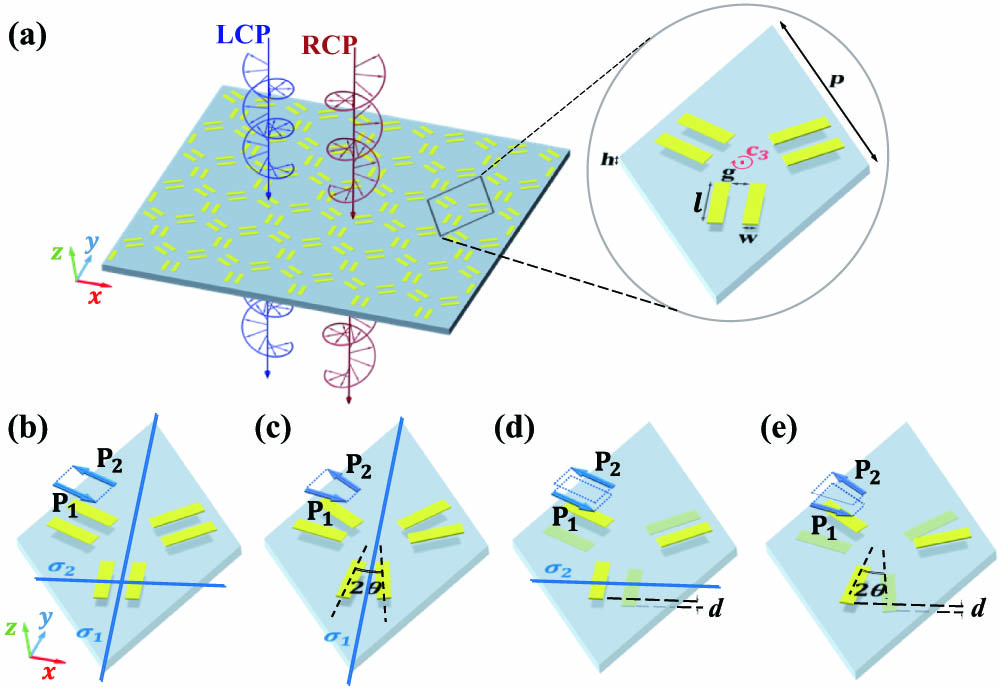
    Fig. 1. (a) Schematic diagram of the original achiral metasurface supporting perfect BICs and a partial magnification of the lattice is shown on the right side. The unit cell with honeycomb lattice constant p consists of three dimers possessing the C3 rotational symmetry. w and l are the width and length of each metal line in a dimer, respectively, and the gap between parallel metal wires is set to g. (b) Parallel metal wires and their lattice hosting dual BIC resonances. Two types of mirror symmetry planes, σ1 and σ2, satisfied by the dimer are indicated. (c), (d) Metal wires rotated by θ or vertically offset by d, respectively, and the unit cell of their lattice hosting dual quasi-BIC resonances but still no chirality. (e) Metal wires rotated by θ and vertically offset by d, and the unit cell of their lattice hosting dual quasi-BIC resonances with chirality. All metal wires are identical and the colors indicate location on different sides of dielectric slab. Relative orientation and offset of electric dipole moments characterizing BIC and quasi-BIC eigenstates are shown on the top for each dimer type.
    Evolution of transmission spectra versus (a) divergence angle θ and (b) vertical d. (c), (d) Simulated transmission spectra of dual BICs by sweeping θ from −10° to 10° at d=0 and d from 0 to 3 mm at θ=0°, respectively.
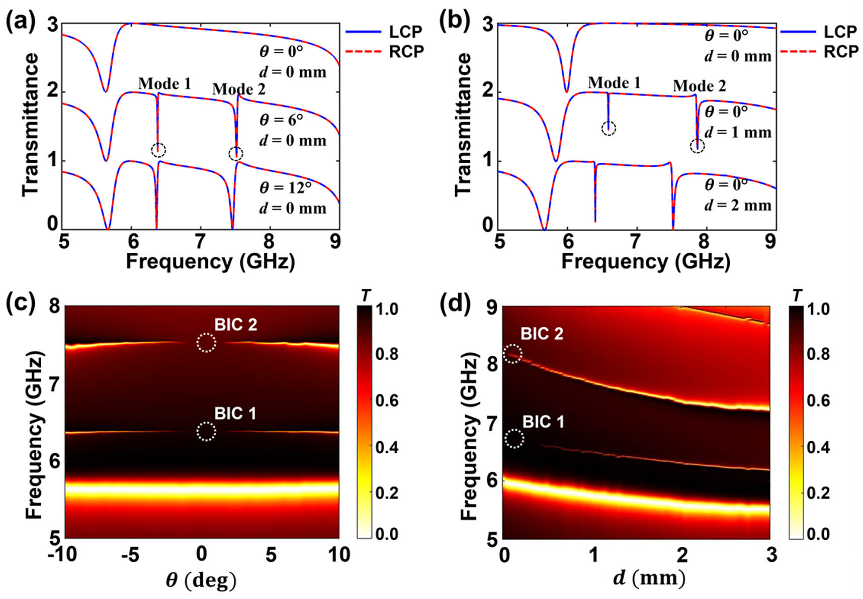
    Fig. 2. Evolution of transmission spectra versus (a) divergence angle θ and (b) vertical d. (c), (d) Simulated transmission spectra of dual BICs by sweeping θ from 10° to 10° at d=0 and d from 0 to 3 mm at θ=0°, respectively.
    (a) Surface current distribution of dual BICs. The unit cell possesses in-plane and out-of-plane mirror asymmetry. (b) Surface current distribution of dual quasi-BICs at θ=0° and d≠0. (c) Surface current distribution of dual quasi-BICs at d=0 and θ≠0°.
    Fig. 3. (a) Surface current distribution of dual BICs. The unit cell possesses in-plane and out-of-plane mirror asymmetry. (b) Surface current distribution of dual quasi-BICs at θ=0° and d0. (c) Surface current distribution of dual quasi-BICs at d=0 and θ0°.
    Dependence of transmittance spectra of the structure on divergence angle θ at (a) d=2.2 mm and (b) d=−2.2 mm. The blue and red lines represent LCP and RCP waves, respectively. (c) CD spectra of the structure with d=−2.2 mm versus rotated angles. (d) Circular dichroism with varying θ at dual quasi-BICs frequencies.
    Fig. 4. Dependence of transmittance spectra of the structure on divergence angle θ at (a) d=2.2  mm and (b) d=2.2  mm. The blue and red lines represent LCP and RCP waves, respectively. (c) CD spectra of the structure with d=2.2  mm versus rotated angles. (d) Circular dichroism with varying θ at dual quasi-BICs frequencies.
    (a) Schematic diagram of the original achiral metasurface supporting perfect BICs. (b) Schematic diagram of the microwave experimental setup. Measured (solid lines) and simulated (dashed lines) transmittance spectra of the normally incident co-polarized wave at (c) d=−2.2 mm and (d) d=2.2 mm. The corresponding circular dichroism spectra at (e) d=−2.2 mm and (f) d=2.2 mm.
    Fig. 5. (a) Schematic diagram of the original achiral metasurface supporting perfect BICs. (b) Schematic diagram of the microwave experimental setup. Measured (solid lines) and simulated (dashed lines) transmittance spectra of the normally incident co-polarized wave at (c) d=2.2  mm and (d) d=2.2  mm. The corresponding circular dichroism spectra at (e) d=2.2  mm and (f) d=2.2  mm.
    (a) Construction of the pattern containing numbers “0” and “1.” Insets show the partially magnified lattice. (b) Electric field intensity distributions (2 mm from the surface) of the proposed metasurface at 6.35 GHz and 7.43 GHz under the normal incidence of circularly polarized waves.
    Fig. 6. (a) Construction of the pattern containing numbers “0” and “1.” Insets show the partially magnified lattice. (b) Electric field intensity distributions (2 mm from the surface) of the proposed metasurface at 6.35 GHz and 7.43 GHz under the normal incidence of circularly polarized waves.
    Fano fitting of dual quasi-BICs at (a) θ=6° and (b) θ=12° with d=0 mm.
    Fig. 7. Fano fitting of dual quasi-BICs at (a) θ=6° and (b) θ=12° with d=0  mm.
    RCP and LCP transmittance spectra of chiral metasurface with (a) quasi-BIC1 and (b) quasi-BIC2 uncoupled from RCP waves for different dielectric loss tangent tan(δ) of substrate. The insets indicate the simulated minimum transmittance with varying tan(δ). Spectra of (c) transmittance and (d) CD of metasurface hosting maximum chiral dual quasi-BICs with different tan(δ).
    Fig. 8. RCP and LCP transmittance spectra of chiral metasurface with (a) quasi-BIC1 and (b) quasi-BIC2 uncoupled from RCP waves for different dielectric loss tangent tan(δ) of substrate. The insets indicate the simulated minimum transmittance with varying tan(δ). Spectra of (c) transmittance and (d) CD of metasurface hosting maximum chiral dual quasi-BICs with different tan(δ).
    (a) Transmittance spectra of the structure at d=−15.5 μm and θ=8°. The blue and red lines represent LCP and RCP waves, respectively. (b) CD value of the structure with d=−15.5 μm at opposite rotation angles.
    Fig. 9. (a) Transmittance spectra of the structure at d=15.5  μm and θ=8°. The blue and red lines represent LCP and RCP waves, respectively. (b) CD value of the structure with d=15.5  μm at opposite rotation angles.
    Xin Qi, Jiaju Wu, Feng Wu, Song Zhao, Chao Wu, Yueyang Min, Mina Ren, Yufei Wang, Haitao Jiang, Yunhui Li, Zhiwei Guo, Yaping Yang, Wanhua Zheng, Hong Chen, Yong Sun. Observation of maximal intrinsic chirality empowered by dual quasi-bound states in the continuum in a planar metasurface[J]. Photonics Research, 2024, 12(2): 244
    Download Citation