• Chinese Optics Letters
  • Vol. 15, Issue 6, 062202 (2017)
Tong Yang, Guofan Jin, and Jun Zhu*
Author Affiliations
  • State Key Laboratory of Precision Measurement Technology and Instruments, Department of Precision Instrument, Tsinghua University, Beijing 100084, China
  • show less
    DOI: 10.3788/COL201715.062202 Cite this Article Set citation alerts
    Tong Yang, Guofan Jin, Jun Zhu. Design of image-side telecentric freeform imaging systems based on a point-by-point construction-iteration process[J]. Chinese Optics Letters, 2017, 15(6): 062202 Copy Citation Text show less
    Determination of the footprints of each field on surface M. (a) The size of the footprint of each field on surface M is approximately determined when the F-number and dz are given. (b) The locations of the footprints for different fields on surface M are also approximately determined based on the EFL, FOV, and the requirement of image-side telecentricity.
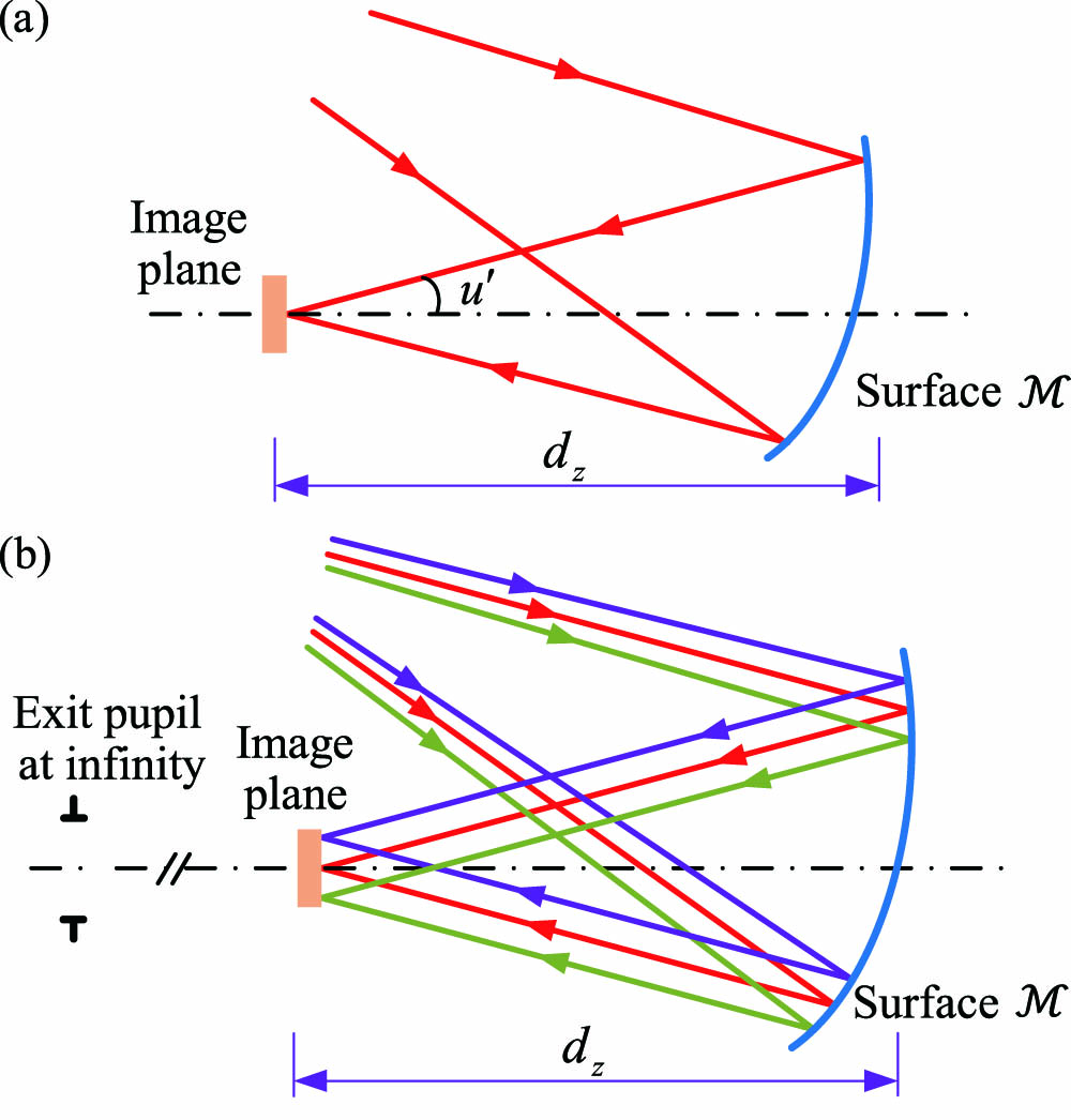
    Fig. 1. Determination of the footprints of each field on surface M. (a) The size of the footprint of each field on surface M is approximately determined when the F-number and dz are given. (b) The locations of the footprints for different fields on surface M are also approximately determined based on the EFL, FOV, and the requirement of image-side telecentricity.
    Reverse ray trace from the end of the system to the surface M. The words within the angle brackets represent the functions in the original system.
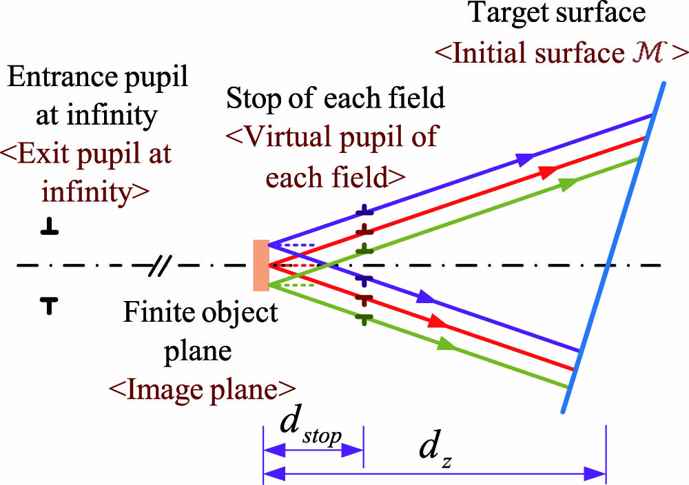
    Fig. 2. Reverse ray trace from the end of the system to the surface M. The words within the angle brackets represent the functions in the original system.
    Design steps of the starting point for the first design example. (a) Initial system. (b) The system after generating freeform M1 and M2. (c) The system after generating freeform M3. (d) The system after the repeat design process.
    Fig. 3. Design steps of the starting point for the first design example. (a) Initial system. (b) The system after generating freeform M1 and M2. (c) The system after generating freeform M3. (d) The system after the repeat design process.
    Reverse ray trace from the ideal image points to M3.
    Fig. 4. Reverse ray trace from the ideal image points to M3.
    Final design result of the first design example. (a) Optical layout. (b) Distortion grid. (c) MTF plot.
    Fig. 5. Final design result of the first design example. (a) Optical layout. (b) Distortion grid. (c) MTF plot.
    (a) Initial system of the second design example. (b) The system after the point-by-point design process for the second example.
    Fig. 6. (a) Initial system of the second design example. (b) The system after the point-by-point design process for the second example.
    Final design result of the second design example. (a) Optical layout. (b) Distortion grid. (c) MTF plot.
    Fig. 7. Final design result of the second design example. (a) Optical layout. (b) Distortion grid. (c) MTF plot.
    Tong Yang, Guofan Jin, Jun Zhu. Design of image-side telecentric freeform imaging systems based on a point-by-point construction-iteration process[J]. Chinese Optics Letters, 2017, 15(6): 062202
    Download Citation