State Key Laboratory of Precision Measurement Technology and Instruments, Department of Precision Instrument, Tsinghua University, Beijing 100084, China
Tong Yang, Guofan Jin, Jun Zhu. Design of image-side telecentric freeform imaging systems based on a point-by-point construction-iteration process[J]. Chinese Optics Letters, 2017, 15(6): 062202
Copy Citation Text
In this Letter, we present a novel design method of image-side telecentric freeform imaging systems. The freeform surfaces in the system can be generated using a point-by-point design approach starting from an initial system consisting of simple planes. The proposed method considers both the desired object–image relationships and the telecentricity at the image-side during the design process. The system generated by this method can be taken as a good starting point for further optimization. To demonstrate the benefit and feasibility of our method, we design two freeform off-axis three-mirror image-side telecentric imaging systems in the visible band. The systems operate at F/1.9 with a 30 mm entrance pupil diameter and 5° diagonal field-of-view. The modulation-transfer-function curves are above 0.69 at 100 lps/mm.
The image-side telecentric system is a kind of system with important applications. (1) Telecentricity can be used to eliminate the magnification change due to the longitudinal position change of the image plane[1]. This is very important for many measurement systems. (2) Image-side telecentricity can improve the relative illumination over the full field-of-view (FOV) on the image plane[2,3]. Additionally, imaging systems are used in a flipped manner to sometimes generate parallel light beams. If the original system is image-side telecentric, the relative illumination over the full FOV can also be improved. (3) Image-side telecentric configuration can be used to avoid color shading caused by red-green-blue (RGB) color separation for three CCD color cameras[1]. Additionally, image-side telecentricity can improve color uniformity for flipped imaging systems, for example, the electronic viewfinder[4]. (4) For the cameras using CCD or CMOS sensors with microlens arrays, image-side telecentricity of the system is required. In this way, the angle at which the chief ray strikes the focal plane can be controlled to match the acceptance cone of the array in order to avoid vignetting of the incoming radiation and increase the sensitivity[5].
In recent years, developments in advanced manufacturing technologies have resulted in freeform surfaces being successfully applied to imaging fields[6,7]. Freeform optical surfaces have many more variables than conventional spheres and aspheres, and they can offer more degrees of design freedom for optical designs[8,9]. Consequently, freeform surfaces can benefit high-performance optical systems design, especially for the systems with special functions, such as image-side telecentric systems. Traditional freeform telecentric systems design is to first find a starting point from existing patents or systems based on the system specifications and configuration. Sometimes the design can also start from a first-order starting point. Then, further optimization with optical design software is conducted to achieve the final design result. Some freeform telecentric designs have been achieved using this design framework[4,10–12]. This design method conforms to the traditional design strategy that has been used for decades and is easy to comprehend and study. If we can find a good starting point that is telecentric and matches the required system specifications and configuration, the final design can be easily generated. However, for telecentric systems, especially for those systems with asymmetric configurations, viable starting points for specific design forms are generally limited. So, designers may have to find other systems as the starting points, whose configuration, number of elements, and system specifications are generally far from the current design. In addition, telecentricity is not generally guaranteed. In this way, the design will be very difficult, and extensive human effort is required. An alternative way to conduct the freeform optical design process is to use direct design methods of freeform surfaces[13–17]. They can provide starting points for subsequent software optimization[18]. However, many of these methods have restrictions on the number of fields or number of surfaces used in the design process, which limit the applications of these methods. More importantly, neither of these methods can realize image-side telecentricity during the design.
In this Letter, we present a novel design method for image-side telecentric freeform imaging systems. The proposed method considers both the desired object–image relationships and telecentricity at the image-side during the design process. The unknown freeform surfaces in the system are generated based on the point-by-point construction-iteration (CI) process. This is, to the best of our knowledge, the first time that the design of a telecentric system is realized by a point-by-point design approach. The system generated by this method can be taken as a good starting point for further optimization using optical design software. To demonstrate the benefit and feasibility of the proposed method, we designed two freeform off-axis three-mirror image-side telecentric imaging systems in the visible band. Each system has an F-number of 1.9 with a 30 mm entrance pupil diameter and 5° diagonal FOV. The modulation-transfer-function (MTF) curves of the systems are above 0.69 at 100 lps/mm.
Sign up for Chinese Optics Letters TOC. Get the latest issue of Chinese Optics Letters delivered right to you!Sign up now
The whole design process starts from an initial system consisting of decentered and tilted planes. Generally, before the design of an optical system, the configuration of the system is generally determined based on the requirements. To maintain the desired configurations, the initial planes should be located approximately at the places where the final freeform surfaces are expected to be. In addition, the initial planes should redirect the light rays approximately as the final freeform system does.
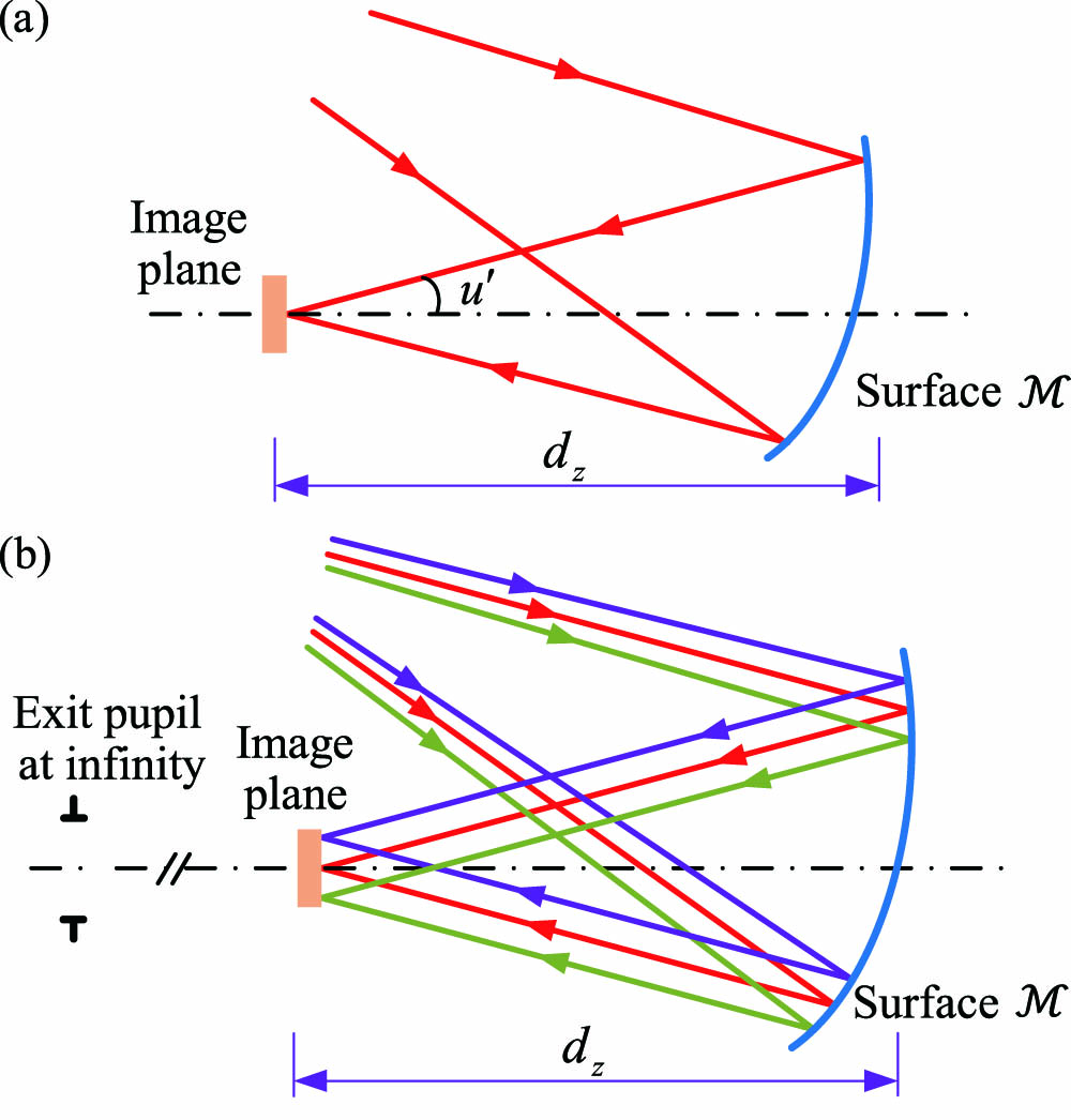
In our design approach, the freeform surfaces will be generated using point-by-point direct design methods. However, neither of the existing direct design methods can realize image-side telecentricity during the design. To solve this problem, here, we will go back to some key natures of the telecentric systems. Generally, before the design of an optical system, some parameters of the system can be determined. (1) The system specifications, such as the FOV, the F-number, and the effective focal length (EFL) have been determined. (2) In order to eliminate light obscurations and make room for some other devices, the distance between the image plane and the last surface of the system can be approximately determined. To achieve the above parameters, the footprints of the sample fields on the surface is crucial[19]: (1) The F-number of the system is given before the design, and the marginal ray slope angle at the image plane can be determined, as shown in Fig. 1(a). As is also given, the size of the footprint of each field on surface is approximately determined. (2) As the system is telecentric at the image side, the location of the exit pupil of the system is at infinity, and the incident angle of the chief ray for each field on the image plane is zero in the ideal case. In addition, the image point of each field can be calculated based on the given EFL. In this way, the locations and directions of the light beams for different fields are determined, and the locations of the footprints for different fields on surface are also approximately determined, as shown in Fig. 1(b). As we can see, based on the system specifications and the requirements of telecentricity, the ideal footprints of the different fields on surface can be determined. In other words, to realize the given system specifications and the image-side telecentricity, the feature light rays of multiple fields and different pupil coordinates coming from the object space should be redirected by the surfaces before in order to generate the desired footprints on surface . Particularly, stronger control can be taken on the light rays in the central part of the aperture in order to better control the chief rays and achieve image-side telecentricity. We can use the following procedures to design the telecentric systems. First, the freeform surfaces before can be generated to realize the desired footprints on surface . Then, the freeform surface is generated to redirect the rays to their ideal image points on the image plane.
Figure 1.Determination of the footprints of each field on surface . (a) The size of the footprint of each field on surface is approximately determined when the F-number and are given. (b) The locations of the footprints for different fields on surface are also approximately determined based on the EFL, FOV, and the requirement of image-side telecentricity.
To realize the point-by-point design of the freeform surfaces before surface , the target points for the feature light rays on surface should be calculated. Here, we can use a reverse ray trace from the end of the system to surface to obtain these points. As shown in Fig. 2, the ideal image point of each field can be calculated based on the given EFL and the corresponding field angle. These points are taken as the ideal “object points” at a finite distance in the reverse ray trace. The initial surface is taken as the “target surface”. As the system is telecentric at the image side, the location of the exit pupil of the system is at infinity, and the incident angle of the chief ray for each field on the image plane is zero in the ideal case. In the reverse ray trace, the exit pupil is the “entrance pupil”, and the chief ray for each field should be perpendicular to the “object plane”. Here, for each field used in the design, we can use a specific stop to confine the light beam. The stop surface for each field is parallel to the “object plane”. The link line between the center of each stop and the corresponding “object point” of each field is perpendicular to the “object plane.” Each stop is actually a virtual pupil for the corresponding field in the original system. If the distance between the stop and the “object plane” is , the diameter of the stop can be calculated with the following relationship: where denotes the entrance pupil diameter, and denotes the F-number. Then, the intersections of the incident feature rays with surface can be taken as the ideal target points for the corresponding feature rays when generating the surfaces before .
Figure 2.Reverse ray trace from the end of the system to the surface . The words within the angle brackets represent the functions in the original system.
We can now generate the freeform surfaces before surface . Here, we use the point-by-point CI method to generate the freeform surfaces[17]. Compared with other direct design methods, which have a restriction on the number of field points considered in the design process (or sometimes a wide FOV but only considering chief rays[14]), this method considers the feature light rays of multiple fields and different pupil coordinates. This meets the requirements of actual imaging systems that work for a certain beam size and a certain FOV. The goal of the CI process is redirecting the discrete feature light rays to their ideal target points on the target surface. With this goal, the data points corresponding to the feature rays are calculated, and then the freeform surfaces are obtained. The CI process has two stages. In the preliminary surfaces-construction stage, the unknown freeform surfaces are generated successively one-by-one starting from the initial planes. The coordinates and surface normals of the data points on each unknown surface are calculated in order to redirect the feature rays to their target points on surface . Then, a surface-fitting method based on the least-squared algorithm that considers both the coordinates and surface normals is used to obtain the freeform surface expression[20]. This freeform surface is used to replace the corresponding initial planar surface. Then, an iteration stage is conducted for these surfaces[17]. These freeform surfaces are taken as the new initial surfaces, and new freeform surfaces can be regenerated. The iteration process can be repeated to reduce the deviation of the actual intersections of rays with surface from the ideal target points. With the above steps, the freeform surfaces before surface can be generated. Finally, freeform surface is constructed in order to redirect the feature light rays to their ideal image points, respectively. Details of the CI process can be found in Ref. [17].
At this time, we have obtained all of the freeform surfaces in the system. However, it can be seen that there is a significant difference in the surface shape between the new surface and the initial planar . Consequently, the ideal footprints on initial surface cannot be ensured, and the exit pupil of the system may be not located at infinity. Here, we can use a repeat design process of the surfaces to solve this problem[19]. The repeat design process of the freeform surfaces is actually a repetition of all of the design steps demonstrated earlier in this Letter, starting from the initial system again. The only difference is that the new surface is taken as the new initial surface . In other words, the new initial system contains the original initial planes before surface and the new initial freeform surface . In this way, as the shape of the new initial surface is closer to surface in the final system, the surface calculated in this repeat design process will be similar to this new initial surface . As a result, the target points of the feature rays on the new initial surface can be approximately ensured, and the image-side telecentricity can be better maintained.
Based on the design method presented above, two freeform off-axis three-mirror image-side telecentric imaging systems have been designed. The first example has a traditional reflective triplet configuration with an F-number of 1.9, 30 mm entrance pupil diameter, and FOV. The system works under the visible band. An initial system consisting of decentered and tilted planes was first established based on the desired system configuration, as shown in Fig. 3(a). The secondary plane mirror (M2) was taken as the aperture stop. The system used a biased FOV in the vertical direction with (0°, ) as the central field. Six sample fields over the half-full FOV were employed in the CI process, which were (0°, ), (0°, ), (0°, ), (1.5°, ), (1.5°, ), and (1.5°, ). A reverse ray trace from the ideal image points to M3 (surface in this system) was conducted to obtain the ideal target points of the feature rays for designing M1 and M2, as shown in Fig. 4. Each field has its specific stop to confine the light beam. Next, the freeform M1 and M2 can be generated based on the CI method to make the feature light rays be redirected to the target points approximately, as shown in Fig. 3(b). Next, the freeform M3 was generated with the point-by-point construction method in order to redirect the feature light rays to their ideal image points on the image plane respectively, as shown in Fig. 3(c). No specific constraints are added on the power distributions in generating the freeform surfaces. In this design example of this Letter, M3 has the largest optical power. If designers have specific requirements on power distribution, the specific powers can be approximately achieved by adjusting the target points during the preliminary surfaces-construction stage in the CI process[9]. It can be seen that there is a significant difference in the surface shape between the new freeform M3 and the initial planar M3. Consequently, the ideal footprints on initial surface M3 cannot be ensured, and the exit pupil of the system may be not located at infinity. To solve this problem, a repeat design process can be employed. The new initial system contains the original initial planar M1 and M2 and the new initial freeform surface M3. Then, the freeform M1, M2, and M3 were regenerated with all of the design steps, as shown in Fig. 3(d). The incident angle of the chief rays on the image plane over the full FOV is approximately between 0.165° and 0.736°. This system was taken as a good starting point for further optimization with optical design software. During the freeform system design, a smaller number of freeform terms should be used. In the two design examples, the freeform surface type is XY polynomial surface. As it has been discussed in Refs. [21–23], there is a relationship between the freeform surface term coefficients and aberrations. XY polynomial surface up to the fourth order corresponds to primary aberrations (or fourth-order wave aberrations), which are the dominant aberrations in the optical system before aberration correction. As a result, during the point-by-point design stage of freeform surfaces, a fourth-order XY polynomial surface with base conic was used, and it is adequate for a starting point design. During the optimization process, we still used fourth-order XY polynomials in the beginning. However, at the final stage of the optimization process, we found the image quality was limited by higher-order aberrations (sixth-order wave aberrations). So, we further employed a sixth-order XY polynomial surface with base conic to correct the higher-order aberrations and achieve a satisfying result. Since the optical system is symmetric about the YOZ plane, only the even items of in XY polynomials are used. The layout of the final system is shown in Fig. 5(a). The incident angle of the chief rays on the image plane over the full FOV is between approximately 0.06° and 0.745° for the final system. The sizes of M1, M2, and M3 are , , and , respectively. The overall volume of the system is about . The average root mean square (RMS) spot diameter over the full FOV is 0.002 mm. The distortion grid of the system is as shown in Fig. 5(b). The MTF plot of the final system is given in Fig. 5(c), whose value is above 0.69 at 100 lps/mm.
Figure 3.Design steps of the starting point for the first design example. (a) Initial system. (b) The system after generating freeform M1 and M2. (c) The system after generating freeform M3. (d) The system after the repeat design process.
Another freeform off-axis three-mirror image-side telecentric system working under the visible band has been designed to better demonstrate the feasibility of the proposed design method. The system has an F-number of 1.9, 30 mm entrance pupil diameter, and FOV. The system has a very compact configuration, which is similar to the imaging system given by Fuerschbach et al.[24]. An initial system consisting of decentered and tilted planes was first established based on the desired system configuration, as shown in Fig. 6(a). M2 was taken as the aperture stop. The system generated by the proposed point-by-point design method is shown in Fig. 6(b). The incident angle of the chief rays on the image plane over the full FOV is between approximately 0.029° and 0.31°. This system was taken as a good starting point for further optimization. The layout of the final system is shown in Fig. 7(a). The incident angle of the chief rays on the image plane is between approximately 0.012° and 0.173°. The sizes of M1, M2, and M3 are , , and , respectively. The overall volume of the system is about . The average RMS spot diameter over the full FOV is 0.0019 mm. The distortion grid of the system is as shown in Fig. 7(b). The MTF plot of the final system is given in Fig. 7(c), whose value is above 0.7 at 100 lps/mm.
Figure 6.(a) Initial system of the second design example. (b) The system after the point-by-point design process for the second example.
In conclusion, we present a novel design method of image-side telecentric freeform imaging systems based on the point-by-point CI process. This is, to the best of our knowledge, the first time that the design of a telecentric system is realized by a point-by-point design approach. The benefit and feasibility of the proposed method are demonstrated by designing two freeform off-axis three-mirror image-side telecentric imaging systems in the visible band.
References
[1] M. Watanabe, S. K. Nayar. Lect. Notes Comput. Sci., 1065, 439(1996).
Tong Yang, Guofan Jin, Jun Zhu. Design of image-side telecentric freeform imaging systems based on a point-by-point construction-iteration process[J]. Chinese Optics Letters, 2017, 15(6): 062202