• Photonics Research
  • Vol. 11, Issue 8, 1423 (2023)
Da-Jie Yang1、2、*, Song-Jin Im3、5, Hai-Wen Huang1, Chol-Song Ri3, Kum-Dong Kim3, Kil-Song Song3, Ji-Cai Liu1、2, and Qu-Quan Wang4、6
Author Affiliations
  • 1Mathematics and Physics Department, North China Electric Power University, Beijing 102206, China
  • 2Hebei Key Laboratory of Physics and Energy Technology, North China Electric Power University, Baoding 071000, China
  • 3Department of Physics, Kim Il Sung University, 02-381-4410 Pyongyang, Republic of Korea
  • 4Department of Physics, Southern University of Science and Technology, Shenzhen 518055, China
  • 5e-mail: sj.im@ryongnamsan.edu.kp
  • 6e-mail: qqwang@sustech.edu.cn
  • show less
    DOI: 10.1364/PRJ.488215 Cite this Article Set citation alerts
    Da-Jie Yang, Song-Jin Im, Hai-Wen Huang, Chol-Song Ri, Kum-Dong Kim, Kil-Song Song, Ji-Cai Liu, Qu-Quan Wang. Anomalous plasmon coupling and Fano resonance under structured light[J]. Photonics Research, 2023, 11(8): 1423 Copy Citation Text show less
    Interplay between optical OAM and SAM. (a) Schematic illustration of a nanoparticle polarized by an OAM beam with a helical wavefront. (b) Azimuthal phase gradient in the plane transverse to the propagation direction of a vortex beam in a spin-orbital state of |–1,1⟩. The yellow circle schematically refers to the nanoparticle under the illumination of a vortex beam. SAM and OAM induced particle polarizations are indicated by the green arrow and blue arrow, respectively.
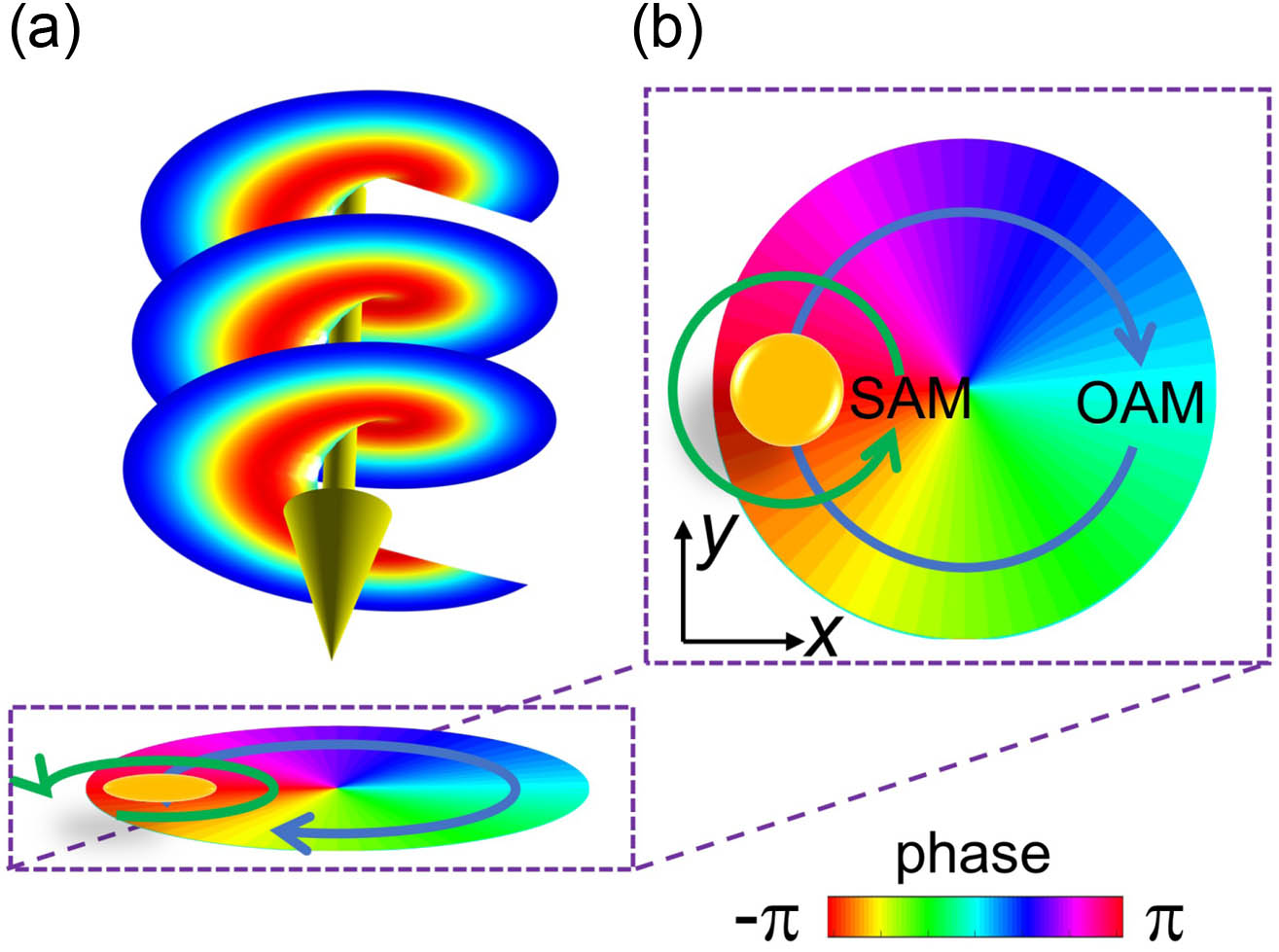
    Fig. 1. Interplay between optical OAM and SAM. (a) Schematic illustration of a nanoparticle polarized by an OAM beam with a helical wavefront. (b) Azimuthal phase gradient in the plane transverse to the propagation direction of a vortex beam in a spin-orbital state of |1,1. The yellow circle schematically refers to the nanoparticle under the illumination of a vortex beam. SAM and OAM induced particle polarizations are indicated by the green arrow and blue arrow, respectively.
    LSPR of single particles on the center of vortex beams. Optical scatterings of |–1,1⟩ light by a gold nanorod located on the beam center and orientated perpendicular to (red) and along (black) the propagating direction. The radius and length of the nanorod are 20 nm and 100 nm, respectively. The configurations and surface charge distributions are shown in the insets bordered with the corresponding colors.
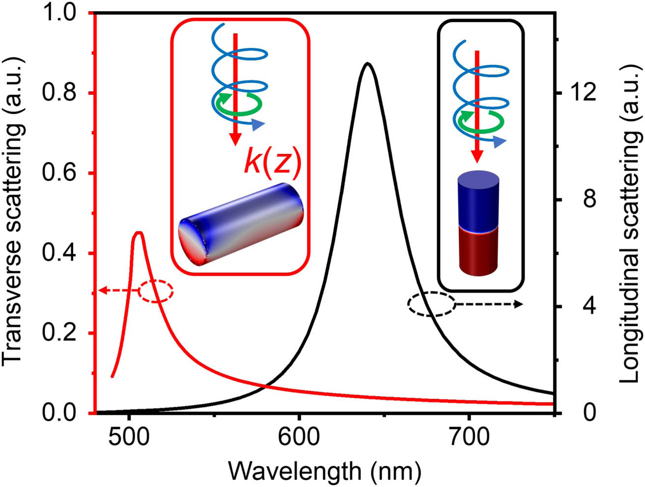
    Fig. 2. LSPR of single particles on the center of vortex beams. Optical scatterings of |1,1 light by a gold nanorod located on the beam center and orientated perpendicular to (red) and along (black) the propagating direction. The radius and length of the nanorod are 20 nm and 100 nm, respectively. The configurations and surface charge distributions are shown in the insets bordered with the corresponding colors.
    LSPR of single particles off the beam center of a linearly polarized vortex beam (|σ,l⟩ equals |0,1⟩). (a) Four different situations when the nanorod is off-center. The color map shows the phase gradient, and the white arrows show the instantaneous electric field. (b), (c) Optical scatterings of the vortex beam by a nanorod oriented along the polarization direction (Ex) of light and offset along the y and x axes from the center (blue line) by a distance of 20 nm (cyan), 50 nm (yellow line), and 80 nm (red line), respectively. (d) Optical scatterings of the vortex beam by a nanorod oriented along Hy and offset along the y (yellow line) and x axes (green line).
    Fig. 3. LSPR of single particles off the beam center of a linearly polarized vortex beam (|σ,l equals |0,1). (a) Four different situations when the nanorod is off-center. The color map shows the phase gradient, and the white arrows show the instantaneous electric field. (b), (c) Optical scatterings of the vortex beam by a nanorod oriented along the polarization direction (Ex) of light and offset along the y and x axes from the center (blue line) by a distance of 20 nm (cyan), 50 nm (yellow line), and 80 nm (red line), respectively. (d) Optical scatterings of the vortex beam by a nanorod oriented along Hy and offset along the y (yellow line) and x axes (green line).
    Anomalous plasmon couplings of two parallel nanorods under vortex beams. Optical spectra of two parallel nanorods located end-to-end (black line) or side-by-side (red line) and oriented (a) along the electric field direction and (b) along the light propagation direction under a linearly polarized vortex beam (l equals 1). The original longitudinal plasmon spectrum of the single nanorod is shown by the blue lines. The insets bordered with black and red show the surface charge distributions at the corresponding peaks. E and k indicate the electric field direction and light propagation direction, respectively.
    Fig. 4. Anomalous plasmon couplings of two parallel nanorods under vortex beams. Optical spectra of two parallel nanorods located end-to-end (black line) or side-by-side (red line) and oriented (a) along the electric field direction and (b) along the light propagation direction under a linearly polarized vortex beam (l equals 1). The original longitudinal plasmon spectrum of the single nanorod is shown by the blue lines. The insets bordered with black and red show the surface charge distributions at the corresponding peaks. E and k indicate the electric field direction and light propagation direction, respectively.
    Fano resonances by a pair of perpendicular nanorods under vortex beams. (a) Configurations of two perpendicular nanorods located at different positions of a vortex beam (|σ,l⟩ equals |0,1⟩). Optical scatterings of the vortex beam by this pair of perpendicular nanorods offset (b) in the second and fourth quadrants and (c) in the first and third quadrants. The insets in (b) show the surface charge distributions at the resonance peaks marked by the hollow and solid star symbols.
    Fig. 5. Fano resonances by a pair of perpendicular nanorods under vortex beams. (a) Configurations of two perpendicular nanorods located at different positions of a vortex beam (|σ,l equals |0,1). Optical scatterings of the vortex beam by this pair of perpendicular nanorods offset (b) in the second and fourth quadrants and (c) in the first and third quadrants. The insets in (b) show the surface charge distributions at the resonance peaks marked by the hollow and solid star symbols.
    Fano resonances by a dimer consisting of a horizontal nanorod and a vertical nanorod under a linearly polarized vortex beam (l=1). Optical scatterings of the vortex beam by the dimer with one along the “vertical” light propagation direction and the other along the “horizontal” magnetic field (a) or electric field (b) direction. The insets show the locations of the dimer and the directions of the light propagation and electric field.
    Fig. 6. Fano resonances by a dimer consisting of a horizontal nanorod and a vertical nanorod under a linearly polarized vortex beam (l=1). Optical scatterings of the vortex beam by the dimer with one along the “vertical” light propagation direction and the other along the “horizontal” magnetic field (a) or electric field (b) direction. The insets show the locations of the dimer and the directions of the light propagation and electric field.
    Exy (first row), Ez (second row), and amplitude |E| (third row) on the focal plane of a y-polarized (first column), x-polarized (second column), right-circularly polarized (third column), and right-circularly polarized (fourth column) vortex beam of l=1. The waist radius w0 is 1000 nm, and other parameters are the same as explained in Appendix A.
    Fig. 7. Exy (first row), Ez (second row), and amplitude |E| (third row) on the focal plane of a y-polarized (first column), x-polarized (second column), right-circularly polarized (third column), and right-circularly polarized (fourth column) vortex beam of l=1. The waist radius w0 is 1000 nm, and other parameters are the same as explained in Appendix A.
    Da-Jie Yang, Song-Jin Im, Hai-Wen Huang, Chol-Song Ri, Kum-Dong Kim, Kil-Song Song, Ji-Cai Liu, Qu-Quan Wang. Anomalous plasmon coupling and Fano resonance under structured light[J]. Photonics Research, 2023, 11(8): 1423
    Download Citation