
Bichen PAN, Penghe REN, Tejun ZHOU, Zhenyang CAI, Xiaojun ZHAO, Hongming ZHOU, Lairong XIAO. Microstructure and Property of Thermal Insulation Coating on the Carbon Fiber Reinforced Epoxy Resin Composites [J]. Journal of Inorganic Materials, 2020, 35(8): 947
- Journal of Inorganic Materials
- Vol. 35, Issue 8, 947 (2020)
Abstract
Keywords
Due to high reliability, low maintenance cost and adaptation to a variety of complex and harsh environments, unmanned aerial vehicle (UAV) has become an important tool for environment preservation, geographical mapping, natural disaster monitoring, fire investigation and relief[
According to the different insulation mechanisms, thermal insulation coatings could be divided into radiation thermal insulation coating, barrier-type thermal insulation coating and reflective thermal insulation coating[
By combining highly reflective materials with low thermal conductivity materials, a portion of the thermal insulation coating has both high reflectivity and low thermal conductivity. Wang, et al[
1 Experimental
1.1 Materials and experiments
In the present work, to fabricate a thermal insulation coating, the waterborne polyurethane was used as film- forming material, and hollow glass microspheres, titanium dioxide, silicon dioxide and aluminum oxide were used as fillers. Carbon fiber reinforced epoxy resin composites with a thermal expansion coefficient of 30× 10-6 K-1 and a glass transition temperature of 160 ℃ were used as base material. To prepare layer-slurry bonding, TiO2 and waterborne polyurethane were thoroughly mixed for 2 h using ethanol and dispersant as milling medium. To prepare barrier layer slurry, hollow glass microspheres, TiO2, and polyurethane were thoroughly mixed, using water and dispersant as milling medium. To prepare reflective layer slurry, the silica aerogel, the sodium silicate solution, titanium dioxide, silicon dioxide and aluminum oxide were sequentially added to the reaction kettle with stirring. Additionally, the base material was cleaned with distilled water and ethanol. Then, the bonding slurry, barrier slurry and reflective slurry were sequentially sprayed on the base materials. Finally, the cured coating was achieved after drying at room temperature for 24 h.
1.2 Characterization
The thickness of thermal insulation coating was tested by film thickness tester (Filmetrics). The reflectivity and thermal conductivity of thermal insulation coatings were measured using a spectrophotometer (V-1300) and a heat conduction analysis meter (ZDJR-3). The temperature difference of thermal insulation coating was observed via insulation film temperature tester (SXLD-9). The microstructures of the thermal insulation coating were examined using scanning electron microscopy (QTA-200). The thermal insulation coating was heat-treated using a blast drying oven (DHG-9050A). The weight loss of the coating was measured by an incubator and an analytical balance, and a thermal cycle is 30 min. The micro characterization was performed using transmission electron microscopy (G20)[
2 Results and discussion
2.1 Designed microstructure of the thermal insulation coating
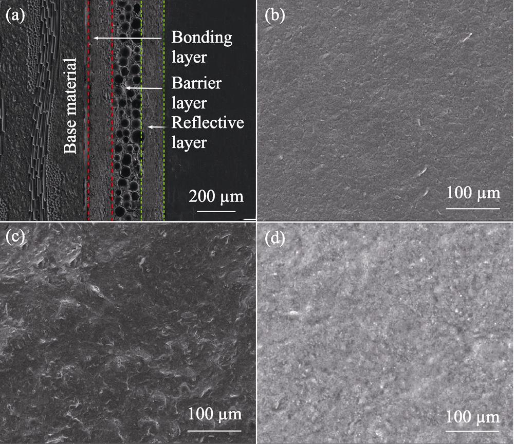
Fig. 1(a) shows the designed microstructure of the thermal insulation coating. It is clear that, in order to improve the adhesion and thermal insulation property of coating, the thermal insulation coating is designed with three functional layers including bonding layer, barrier layer and reflective layer. Due to the difference in thermal expansion coefficient between base material and coating, the expansion of the base material should be much larger than coating. After heating, there are likely to be large compressive stresses in the coating which cause the coating to buckle and flake off, a process known as spalling[
![]()
Figure 1.Designed microstructure of the thermal insulation coating(a) Cross section; (b) Bonding layer surface; (c) Barrier layer surface; (d) Reflective layer surface
A dense and flat surface were presented in the bonding layer (Fig. 1(b)), without obvious defects such as looseness and micro-cracks. However, due to a large difference in particle size between hollow glass microspheres and TiO2, the surface of barrier layer with a small number of broken particles and micro holes were observed as shown in Fig. 1(c). Furthermore, due to a lot of nano-particles addition such as TiO2, SiO2 and Al2O3, a dense surface without obvious defect could be found in reflective layer as shown in Fig. 1(d).
2.2 Thickness optimization of the designed functional layers
The thermal expansion coefficients of carbon fiber reinforced epoxy resin composites, TiO2 and polyurethane are 30×10-6, 9×10⁻⁶, and 120×10-6 K-1, respectively. In order to match the thermal expansion between base material and the coating, TiO2 was mixed with polyurethane in the bonding layer. Thickness of the bonding layer was an important factor in ensuring the service time at the actual temperature. Fig. 2(a) shows the effect of bonding layer thickness on service time at 160 and 190 ℃. With the coating thickness increasing, the service time marked increased. Furthermore, when thickness of bonding coating remained constant, the service time remarkably decreased with the increase of the service temperature. At a coating thickness of 80 μm, the time required for shedding reach 360 and 200 min. Continuous growth in coating thickness has little effect on coating shedding. Therefore, the thickness of the bonding layer is designed to be 80 μm or more.
![]()
Figure 2.Thickness optimization of the designed functional layers(a) Time required for coating to fall off at 160 and 190 ℃; (b) Reflectivity of coatings with different thicknesses of reflective layers; (c) Temperature difference change curves for coatings with different thicknesses of the barrier layer
Fig. 2(b) shows the reflectivity as a function of the reflective layer thickness. When the coating thickness reached up to 90 μm, the coating reflectivity increased obviously with the increase of the coating thickness. A further increase of coating thickness from 90 μm to 150 μm only gave rise to a slight increase. The reflection performance of the coating is related to the thickness of the surface layer, and simply increasing the thickness of the coating does not continuously increase the reflectance. Consequently, the optimum thickness of the reflective layer is about 90 μm.
The thickness of the barrier layer is determined on the basis of the thicknesses of the bonding layer and reflective layer. Fig. 2(c) shows the temperature difference of thermal insulation coatings as a function of the barrier layer thickness, where the thickness of bonding layer and reflective layer were 80 μm and 90 μm, respectively. The temperature difference of the coatings increased with the increase of the holding time. Additionally, it is clear that, the thicker the coating thickness, the longer the temperature stabilize time turns. When the thickness of coating increased from 170 μm to 320 μm, the stabilized time would be prolonged from 15 min to 20 min. The fast-rising zone ranged from 0 μm to 120 μm, and the thermal insulation temperature difference is rapidly increased from 12 ℃ to 20.1 ℃. This huge increase comes from the increase in coating thickness and the decrease in the thermal conductivity of the coating. The stable rising zone range is above 120 μm, and the increase in the thermal insulation temperature difference is mainly due to the increase in coating thickness. Considering the overall performance of the coating, 120 μm is the best choice for the barrier layer.
![]()
Figure 3.Weight loss curves of the thermal insulation coatings at different temperatures
2.3 Property of the thermal insulation coating
To examine the thermal cycling performance of fabricated thermal insulation coating, the weight-loss rate per cycle between 100 ℃ and 190 ℃ of the specimens was measured. A similar characteristic could be seen in all of the coating weight-loss curve exhibits under different temperatures. In the first two cycles, the weight-loss rate of the coating is rapidly increased. This can be mainly related to the volatilization of small molecules. However, when the thermal cycle further increasing, only a slight increase was observed. With room-temperature curing, the coating can reach as thick as 300 μm and some of the small-molecule solvents or auxiliaries are not entirely volatilized[
The macroscopic morphology of the thermal insulation coatings heated at 160 ℃ for 0, 1, 2, and 4 h are shown in Fig. 4. Their coating and substrate material were unchanged when temperature was maintained at 160 ℃ for 1 h. If this temperature was maintained for 2 h, their surface of the coating material turned slightly yellow. Further, when the temperature was maintained for 4 h, the surface of the coating exhibited a uniform light orange color. After heat preservation at 160 ℃ for 1, 2, and 4 h, the coating materials can effectively protect the substrate from failure, indicating good high-temperature insulation performance and that the addition of polyurethane in bonding layer effectively matches the amount of expansion of the base material and reduces thermal stress.
![]()
Figure 4.Macroscopic morphology changes of the coatings when heated at 160 ℃ for different time(a) 0 h; (b) 1 h; (c) 2 h; (d) 4 h
2.4 Failure behaviors of the thermal insulation coating
As shown in Fig. 5(a), due to the polyurethane added to the thermal insulation coating, there was some degree of embrittlement in the coating. In the cross section, cracking occurs between the coating and the base material. The coating fails and falls off when the transverse cracks expand and contact each other. This failure phenomenon can be mainly attributed to the difference between the thermal expansion coefficients of the base and the coating materials. During the extended heating process, different degrees of expansion can be observed, resulting in stress at the base and coating cross section. There is a little bit of micro holes on the coating surface after being heated at 160 ℃ for 4 h (Fig. 5(b)).
![]()
Figure 5.SEM morphology changes of coatings heated at 160 ℃ for 4 h(a) Coating cross-section; (b) Reflective layer surface
Fig.6 shows the morphology of nano-particles before and after the coatings were heated at 160 ℃ for 4 h. It can be seen that all TiO2 particles were nano-sized (<100 nm), but there also appeared a conglomeration because it was rather difficult to disperse nanometer powders on the copper plate after ultrasonic vibration for TEM imaging[
![]()
Figure 6.TEM iamges of nonmetric TiO2 in coatings (a) before and (b) after being heated and corresponding EDS of (c) point 1, (d) point 2, (e) point 3, and (f) point 4 in (a) and (b)
3 Conclusions
In order to prevent the actual temperature of CFRP in fire UAV, a new type of thermal insulation coating has been achieved. The coating included bonding layer, heat insulating layer and reflective layer, with optimal thickness of about 80, 120, and 90 μm, respectively. The designed thermal insulation coating solves the problem of bonding between the coating and the base material, while having a low thermal conductivity of 0.048 W·m-1·K-1 and a high reflectivity of 0.95. On this basis, the comprehensive performance of the thermal insulation coating is characterized as follows: the thermal insulation temperature difference is up to 20.1 ℃; the thermal insulation coating was subjected to thermal shock at 190 ℃ for 6 times, the highest weight loss rate was just 3.7%. Therefore, the thermal insulation coating can work continuously at 160 ℃ for 4 h.
References
[6] F GUO, X CHEN, G WANG et al. Hollow ceramic microspheres prepared by combining electro-spraying with non-solvent induced phase separation method: a promising feedstock for thermal barrier coatings. Materials & Design, 139, 343-350(2018).
[10] Z H LI, F F DUAN, J S HUA et al. Preparation of novel heat-resistant phthalonitrile biphenyl-type novolac resin hollow microspheres. Journal of Central South University, 48, 2597-2605(2017).
[14] H J KIM, H J LEE, D S KIM. Hollow TiO2 flake prepared from TiO2 coated glass flake for solar heat protection and their thermal performance. Materials & Design, 150, 188-192(2018).
[16] K L LU, Z G JI, Z KONG et al. Preparation and thermal insulating properties of antimony doped nano-SnO2 /waterborne polyurethane composite coatings. Journal of Inorganic Materials, 27, 1217-1220(2012).
[17] Z DAI, Z LI, L LI et al. Synthesis and thermal properties of anti- mony doped tin oxide/waterborne polyurethane nanocomposite films as heat insulating materials. Advances in Polymer Technology, 22, 1905-1911(2011).
[19] Y F CHEN, X N TANG, B ZHANG et al. TiO2 and SiO2 composites: preparation and photocatalytic antimicrobial performance. Journal of Inorganic Materials, 34, 1225-1333(2019).


Set citation alerts for the article
Please enter your email address

© Copyright 2018-2021 | Chinese Laser Press. All Rights Reserved 沪ICP备15018463号-20