• Journal of the European Optical Society-Rapid Publications
  • Vol. 18, Issue 1, 2022006 (2022)
Karla Roszeitis1、*, Markas Sudzius1, Alexander Palatnik1, Rebekka Koch2, Jan Carl Budich3, and Karl Leo1
Author Affiliations
  • 1Dresden Integrated Center for Applied Physics and Photonic Materials (IAPP) and Institute for Applied Physics, Technische Universität Dresden, 01062 Dresden, Germany
  • 2Institute for Theoretical Physics, University of Amsterdam, PO Box 94485, 1090 GL Amsterdam, The Netherlands
  • 3Institute for Theoretical Physics, Technische Universität Dresden, 01062 Dresden, Germany
  • show less
    DOI: 10.1051/jeos/2022006 Cite this Article
    Karla Roszeitis, Markas Sudzius, Alexander Palatnik, Rebekka Koch, Jan Carl Budich, Karl Leo. Coherence onset in PT-symmetric organic microcavities: towards directional propagation of light[J]. Journal of the European Optical Society-Rapid Publications, 2022, 18(1): 2022006 Copy Citation Text show less

    Abstract

    For the investigation of non-Hermitian effects and physics under parity-time (PT) symmetry, photonic systems are ideal model systems for both experimental and theoretical research. We investigate a fundamental building block of a potential photonic device, consisting of coupled organic microcavities. The coupled system contains cavities with gain and loss and respects parity-time symmetry, leading to non-Hermitian terms in the corresponding Hamiltonian. Experimentally, two coupled cavities are realized and driven optically using pulsed laser excitation up to the lasing regime. We show that above the lasing threshold, when coherence evolves, the coupled-cavity system starts to operate asymmetrically, generating more light on one side of the device, being characteristic of non-Hermitian PT-symmetric systems. Calculations and simulations on a Su–Schrieffer–Heeger (SSH) chain composed of these PT-symmetric unit cells show the emergence of non-trivial topological features.For the investigation of non-Hermitian effects and physics under parity-time (PT) symmetry, photonic systems are ideal model systems for both experimental and theoretical research. We investigate a fundamental building block of a potential photonic device, consisting of coupled organic microcavities. The coupled system contains cavities with gain and loss and respects parity-time symmetry, leading to non-Hermitian terms in the corresponding Hamiltonian. Experimentally, two coupled cavities are realized and driven optically using pulsed laser excitation up to the lasing regime. We show that above the lasing threshold, when coherence evolves, the coupled-cavity system starts to operate asymmetrically, generating more light on one side of the device, being characteristic of non-Hermitian PT-symmetric systems. Calculations and simulations on a Su–Schrieffer–Heeger (SSH) chain composed of these PT-symmetric unit cells show the emergence of non-trivial topological features.

    1 Introduction

    Recent advances in photonics have revealed a variety of novel phenomena, prominently including non-linear topological properties, that cannot be attained in conventional optical designs [14]. Introducing gain and loss into photonic structures naturally extends the scope to Non-Hermitian (NH) systems. There, combining non-Hermiticity with topology has recently triggered broad attention since, on the one hand, fundamental topological concepts like the bulk-boundary correspondence differ drastically in comparison to their Hermitian counterparts, and, on the other hand, new dissipative phenomena with no Hermitian counterpart occur, such as the non-Hermitian skin-effect and exceptional points [5]. Both unidirectional spectral singularities and topological edge states have been shown in one dimension, and their connection to exceptional points was investigated [6]. Under certain conditions, i.e. when gain and loss are balanced, parity-time (PT) symmetry [7, 8] is still preserved in NH systems, and has striking implications [9, 10]: optically active photonic structures with well-integrated PT-symmetry may become immune to structural defects and disorder or experience spontaneous symmetry breaking and, in this way, allow to engineer light flow [11, 12]. Unidirectional optical elements are required in all-optical components in integrated circuits [13]; they may also pave the road towards a broader vision of invisibility while from inside being still able to see the outside world [14]. Organic materials have the great advantage of inhomogeneously broadened spectral properties, which cover tens of nanometers [15].

    In this paper, we experimentally investigate and characterize a fundamental building block of potential future organic NH topological devices: a system of two planar organic microcavities, which are optically coupled, and may be seen as a unit cell of a NH topological lattice structure. Our setup is designed as a PT-symmetric NH system, where both cavities are identical except for the cavity layers, one of which comprises gain which is balanced by the loss of the other one. The flexibility in engineering optical gain is a key advantage of the organic material system. Above the lasing threshold, we observe clear signatures of an asymmetric behavior that is characteristic for systems with broken PT-symmetry [16]. Being a truly 1D thin-film device that does not require any in-plain perturbation of physical dimension or optical constants, these structures have virtually no limitations on the lateral size of the device, making them particularly attractive for the potential practical applications. Finally, we theoretically analyze how several unit cells of this type may be coupled together to yield a NH Su–Schrieffer–Heeger (SSH) chain – a paradigmatic NH topological system.

    2 Discussion

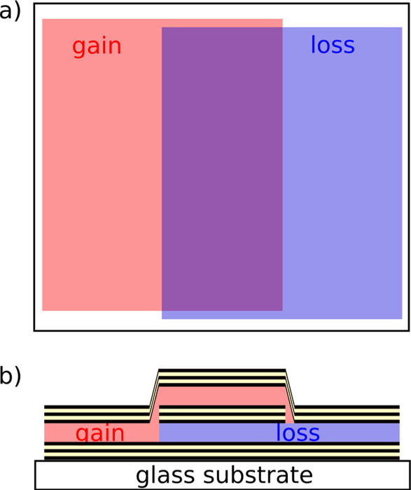
    The experimental gain–loss cell element consists of two planar organic microcavities strongly optically coupled to each other. The structure is shown schematically in Figure 1. The coupled cavities (central area in Fig. 1) are embraced by TiO2/SiO2 distributed Bragg reflectors (DBRs) with 21 layers each of high optical quality and high reflectivity of 99.93% as outer mirrors. A central mirror with lower reflectivity separates gain and loss cavities and controls the optical coupling between them. In this work, we use a TiO2/SiO2 DBR with in total 9 layers of λ/4 optical thicknesses with a reflectivity of 93.96%. The central mirror assures very effective optical coupling between the two cavities.

    Sample schematics with (a) top and (b) side view. Gain and loss cavities are sandwiched between TiO2/SiO2 distributed Bragg reflectors with 21 layers. They do overlap in the central part of the sample, separated by a third distributed Bragg reflector with 9 layers, leading to a coupled system. All reflector layers are of λ/4 optical thickness, cavity layers of λ/2 optical thickness, at design wavelength λD = 620 nm.

    Figure 1.Sample schematics with (a) top and (b) side view. Gain and loss cavities are sandwiched between TiO2/SiO2 distributed Bragg reflectors with 21 layers. They do overlap in the central part of the sample, separated by a third distributed Bragg reflector with 9 layers, leading to a coupled system. All reflector layers are of λ/4 optical thickness, cavity layers of λ/2 optical thickness, at design wavelength λD = 620 nm.

    To keep the structure as close to a PT-symmetric system as possible, we use the same tris-(8-hydroxy quinoline) aluminum (Alq3) organic material for both cavities as a matrix material. It makes up about 98% of the cavity layer and thus pins the refractive index to approximately the same value in both cavities, making it almost perfectly symmetric with respect to the central mirror. To introduce optical gain in one of the cavities, we have doped the Alq3 matrix with approximately 2 wt.% of 4-(dicyanomethylene)-2-methyl-6-(p-dimethylaminostyryl)-4H-pyran (DCM), small organic molecules which are well known as organic laser dye [17]. As we have shown recently, the transient gain coefficient in similar Alq3:DCM systems can reach 600 cm−1 close to its emission maximum at 620 nm under pulsed optical excitation [18]. On the other hand, to introduce optical loss in this spectral region in the bottom cavity, we have co-evaporated Zinc Phthalocyanine (ZnPc) into the Alq3 matrix, which possesses substantial absorption at 620 nm [19] while its emission band is shifted to the red far away from the cavity resonances [20]. The concentration of ZnPc molecules is carefully controlled and chosen such, that the absorption coefficient of the lower cavity is about 300 cm−1 (below 2 wt.%). In this way, absorption can be compensated by transient gain at a certain moment under pulsed excitation.

    Pulsed optical excitation in the Alq3:DCM gain medium leads to complex gain dynamics with time, particularly above lasing threshold [21]. Following photoexcitation, fast non-equilibrium dynamics drive exciton energy down due to vibrational relaxations. If the Alq3 host molecules absorb the pump energy, they get subsequently transferred to DCM guest molecules due to nonradiative Förster-type energy transfer [17]. The duration of this process depends on the host material doping by the guest molecules and can vary over a few orders of magnitude. In the following, the excitons on the DCM site relax further until the lowest energy state is reached, where population inversion is formed [22]. The overall time needed to reach lasing regime after the photoexcitation to the absorption band of Alq3 is pump intensity-dependent in the range of a few tens of picoseconds [21]. Moreover, above lasing threshold, the Alq3:DCM gain medium is known to undergo relaxation oscillations (and thus oscillations in population inversion and gain) with sub-nanosecond periodicity [23].

    We use 10 ns duration pulses to introduce transient gain in one of the cavities, allowing us to reach and surpass the required degree of population inversion and achieve balanced gain and loss at some specific times. Even though the characteristic exciton energy transfer times and relaxation oscillations in Alg3:DCM are much shorter than the pulse duration of the pump laser, PT-related effects still play a substantial role on light propagation in our system. As we demonstrate below, these effects can be indirectly observed in time-integrated measurements.

    As it is schematically shown in Figure 1, all samples show in addition to the central region, where two cavities are strongly coupled, regions with the single cavities with gain on one hand side of the structure and loss on the other. Figure 2a shows maximum values of the white light transmission spectra through all three characteristic areas of the sample. Due to the mechanical tension induced by covering the single cavity regions with the masks and material deposition distortion on the mask edges, the cavity spectral resonances slightly shift across the sample. This is particularly true for the single cavity regions where the masks were used. However, in the coupled cavity region, the resonance shows constant splitting due to the optical coupling over the whole area. In the region where two cavities are strongly coupled, the cavity resonance splits into two modes and the system behaves similar to an optically passive photonic molecule, which possesses two supermodes whose spectral separation depends on the reflectivity of the central mirror and is characterized by the coupling coefficient κ [24].

    (a) Spectral position of the modes across the sample in all three distinct sample regions. (b) Characteristic white light transmission spectrum through the coupled cavity region in experiment (blue) and transfer-matrix simulation (green), and PL spectrum of an Alq3:DCM neat layer.

    Figure 2.(a) Spectral position of the modes across the sample in all three distinct sample regions. (b) Characteristic white light transmission spectrum through the coupled cavity region in experiment (blue) and transfer-matrix simulation (green), and PL spectrum of an Alq3:DCM neat layer.

    The quality factor Q of the cavities for a mode at resonance frequency fr (Q = frf with Δf full width at half maximum) reaches 800 and 920, for the measured modes at 607 nm and 626 nm, respectively. The splitting of the peaks of 19 nm is comparably large to the full width at half maximum of 0.76 nm. In comparison, a transfer-matrix simulation [25] yields quality factors of 1240 and 1300 for the two splitted mode resonances. The experimental values of the quality factor are sparsely lower because of fabrication imperfections and integration over area and angle due to the finite spot size in the experiment.

    The optical design of our structures has been optimized using the transfer matrix (T-matrix) method tso assure that the optical resonances of the system are placed close to the emission and absorption maxima of the DCM and ZnPc cavities, respectively. Figure 2b shows the characteristic transmission spectrum through the coupled cavity region as well as the PL emission spectrum of the Alq3:DCM neat layer. Note, that both optical resonances are spectrally located close to the PL emission maximum of the DCM, and thus, close to the gain maximum of Alq3:DCM [26].

    In the experiments with gain, we excite our structures at 532 nm with nanosecond pulses at 10 kHz repetition rate. We note that the Alq3 cavity matrix does not absorb light at this wavelength. Therefore, the population inversion in Alq3:DCM cavity (gain cavity) is induced solely due to direct optical pumping to the absorption band of the DCM dye. While the ZnPc-based cavity (loss cavity) can also be considered as optically pumped at 532 nm, it shows only very weak emission far below the emission maximum of DCM and thus has no gain at the resonances of the coupled cavity device.

    The optically excited DCM molecules emit in both directions through cavity resonances. However, in contrast to the white light transmission spectra, shown in Figure 2b, which is the same for both probing directions alongside or parallel to the sample normal, the amount of light generated in the gain cavity depends on the detection direction due to the sample asymmetry with respect to the gain/loss distribution in the system.

    By varying the pump beam intensity, we were able to lead the system above the lasing threshold and switch the light emission regime from spontaneous to stimulated. This type of transition can be unambiguously identified from the S-shaped input–output (IO) characteristics in double logarithmic representation. Figure 3 shows IO characteristics of different spots (depicted is the first mode reaching the lasing threshold, which is typically the lower energy mode), measured in two different experimental arrangements, as it is schematically shown in the inset. The coupled-cavity system was pumped through the substrate and absorbing (loss) cavity in one case. In contrast, the emitted light was collected and measured perpendicular to the surface on the opposite side of the sample. In the other arrangement, the sample was flipped by 180° and pumped directly into the gain cavity, while the signal was measured from the substrate side. The extended set of measurements has been conducted at different spots on the sample for both measurement geometries to collect reliable statistics and minimize uncertainty due to optical and structural inhomogeneities.

    Input–output characteristics in forward direction (blue curves, see inset) show an up to one order higher output intensity compared to backward direction measurements (orange curves) in some pump power regimes. The curves stem from different spots on a coupled cavity device. All curves are shifted along x- and y-direction to coincide before lasing starts (green cross), see main text for further information. Pump power ranges for every curve from 10−1 μW to 102 μW energy input into the sample.

    Figure 3.Input–output characteristics in forward direction (blue curves, see inset) show an up to one order higher output intensity compared to backward direction measurements (orange curves) in some pump power regimes. The curves stem from different spots on a coupled cavity device. All curves are shifted along x- and y-direction to coincide before lasing starts (green cross), see main text for further information. Pump power ranges for every curve from 10−1 μW to 102 μW energy input into the sample.

    To compensate for the differences in pumping and detection conditions due to the swap of gain with loss when measuring from the different sides of the sample, we chose to let the input–output curves coincide before the system’s lasing threshold is reached. In one case, the pump laser goes through the absorbing media before reaching the light-emitting medium, causing a shift of the IO curve to higher pump powers due to reduced effective pump power. If the sample is turned, the light emitted from the active medium has to propagate through the absorbing cavity before reaching the detector, reducing the output intensity, leading to a shift to lower luminescence of the IO curve. Therefore, we shifted each measured IO curve by freely chosen factors along both axes. In this way, any discrepancy in the behavior of IO characteristics above lasing threshold unambiguously points to the onset, which has been obtained due to the presence of coherence in the system. Our results show that above the lasing threshold, our system works more effectively and generates more light on the side of the sample which contains gain. It is in close analogy to the uni-directional light propagation in PT-symmetric coupled oscillator systems near the exceptional point, where energy oscillations in the system are no longer symmetric and lead to non-reciprocal propagation of light [27].

    Our latter statement is confirmed by Finite-Difference Time-Domain (FDTD) simulations which include gain and simulate electromagnetic wave packet oscillations in time after the population inversion in the gain cavity is introduced and starts to recombine radiatively. A model resonator structure precisely mimics our coupled cavity, including the number of dielectric layers in the mirrors, cavity thicknesses, and dispersion characteristics of all materials involved. Figure 4 shows the spatial distribution of electric field along the structure as a function of time, which is calculated for four different extinction coefficient values for the absorbing cavity, while the amount of gain stays fixed. The amount of gain is found empirically by varying it over a wide range of values and optimizing the isolation of the bright mode in Figure 4d, as well as the overall emissive performance of the whole device as a function of the extinction coefficient of the absorbing cavity (Fig. 5). For the nonabsorbing cavity (k = 0), the electromagnetic wave oscillates between two cavities as a consequence of the spectral beating of two cavity resonances. The field amplitude decreases slightly with time because photon leakage through the mirrors prevails over optical gain in the system. However, once the extinction coefficient exceeds some critical value in the absorbing cavity, the electric field remains in the cavity with the gain at all times. This particular state gets isolated from losses in the system that respects PT-symmetry and modifies its visibility relative to other states. As a result, the integral characteristics change respectively. For example, the effect is clearly visible on the spectrally- and time-integrated emission signal from the structure, shown in Figure 5.

    Time evolution of the electric field distribution after the population inversion gets introduced into the gain cavity and starts to recombine radiatively. The calculation was done for four different extinction coefficient values for the absorbing cavity, while the amount of gain was kept fixed.

    Figure 4.Time evolution of the electric field distribution after the population inversion gets introduced into the gain cavity and starts to recombine radiatively. The calculation was done for four different extinction coefficient values for the absorbing cavity, while the amount of gain was kept fixed.

    Time- and spectrally-integrated emission signal as a function of the extinction coefficient of a loss cavity.

    Figure 5.Time- and spectrally-integrated emission signal as a function of the extinction coefficient of a loss cavity.

    For the theoretical analysis of coupled unit cells, we employ a tight-binding approximation (TBA), which holds for the electromagnetic eigenmodes of coupled optical cavities [2830]. The cavities take the role of potential wells and the eigenmodes are comparable to electronic wave functions. Closely following reference [28], the eigenfrequencies for a set of coupled cavities with the nth cavity at position nR are,ωk2=Ω21+n0exp-inkRβn1+Δα+n0exp-inkRαn,with Ω the eigenfrequency of a single cavity, k the wave vector, and the overlap integrals αn = ∫dz ε(z) EΩ(z) EΩ(z − nR), βn = ∫dz εΩ(z) EΩ(z) EΩ(z + nR), and Δα = ∫dz ε(z) EΩ(z) EΩ(z) − 1, where εΩ and ε are the space-dependent dielectric functions of a single and coupled cavities, respectively, and EΩ is the eigenmode of a single cavity.

    As eigenmodes of the tight binding model, we use a Lorentzian fit of the electric field distribution of the cavity resonance in a single cavity, calculated with the T-matrix method. With known eigenfunction for a single cavity and dielectric constant of the stack, we calculate the overlap integral between modes in neighboring cavities, since we assume only nearest neighbor interaction. Evaluating the splitting with the tight-binding approximation for two coupled cavities gives a splitting of 14 nm with modes at 611 nm and 625 nm [30], which is in good accordance to the experimental result. A repeated structure of such gain–loss elements with nearest-neighbor couplings can mimic a tight-binding Hamiltonian of a one-dimensional chain, that is non-Hermitian and, since sites with gain and loss are alternating, preserves PT-symmetry.

    The appropriate, effective Hamiltonian describing a single unit cell of this setup reads as,Ĥ=iγââ-iγb̂b̂+tâb̂+b̂â,where â (â) are the annihilation (creation) operators of photons in the gain cavity and analogously b̂ (b̂) in the loss cavity, t is the hopping term obtained by TBA, and γ is the strength of the gain/loss term. The hopping parameter for a chain with N unit cells and quantized momenta kl is defined as,t=1Nlωkl2e-iklR,with the spatial distance R between unit cells.

    Additionally, if the hopping parameters are also alternating, this photonic structure realizes a NH version of the SSH model [5, 31] and thus can feature non-trivial topology. To engineer two different hopping parameters, the spacing between the gain–loss elements has to differ from the internal spacing between the gain and the loss cavity [32].

    To observe topological signatures like edge states in the relevant parameter regime, we found by utilizing exact diagonalization the minimum to be six coupled cavities (three unit cells) arranged in an SSH chain. Figure 6 compares reflectivity spectra of 10 coupled cavities with alternating gain/loss of γ = 1.87 and alternating couplings between the cavities obtained from T-matrix calculations (15 and 11 layer DBR) with the eigenvalues of a non-Hermitian SSH chain. The introduced gain is low enough to keep the whole system below the lasing threshold, thus letting the T-matrix calculations converge. The very sharp spectral features in reflectivity spectra mark optical resonances of the system and are in perfect agreement with TBA calculations. Note, however, that reflectivity spectra show asymmetry and change drastically when light propagation direction is inverted, pointing to a feature of non-Hermiticity [33]. Another remarkable characteristic shows in the reflectivity spectrum: When a plane wave impinges the cavity with gain first, the reflectivity gets enhanced and exceeds 100% in some spectral regions, which would not be possible in an optically passive system. The edge states of the topological system correspond to the modes with coalescing real part at 620 nm, whose imaginary parts cause a strong broadening in the reflectivity spectra. Neither degeneration of modes nor strong mode broadening are detectable in the topological trivial case.

    (a) Reflectivity spectra obtained from T-matrix simulations for a planar wave, impinging on a stack of 10 coupled cavities (separated by 15 and 11 layer DBRs in alternation) normal to the 1D topological chain, shown for two propagation directions. Gain/loss parameter is γ = 1.87. (b) Spectral distribution of eigenvalues of this chain, obtained from the tight-binding model.

    Figure 6.(a) Reflectivity spectra obtained from T-matrix simulations for a planar wave, impinging on a stack of 10 coupled cavities (separated by 15 and 11 layer DBRs in alternation) normal to the 1D topological chain, shown for two propagation directions. Gain/loss parameter is γ = 1.87. (b) Spectral distribution of eigenvalues of this chain, obtained from the tight-binding model.

    3 Conclusion

    In conclusion, we have investigated a coupled organic microcavity system, which could serve as a single unit cell element in topological chain systems. Using a special normalization procedure, which allows comparison of input–output characteristics from the asymmetric structures, we could compare light emission efficiency on both sides of the asymmetric planar device, which contains loss and gain but respects PT-symmetry, in the regime when the system is operated above lasing threshold, i.e., in the coherent regime. Our results show that, above lasing threshold, our system works more effectively and generates more light on the side of the structure, which contains gain and agrees qualitatively well with simulation results. The theoretical analysis of a SSH-type chain of these unit cells shows remarkable features of non-trivial topology starting from a minimum of three coupled unit cells.

    Abbreviations

    References

    [1] M. Segev, M.A. Bandres. Topological photonics: Where do we go from here?. Nanophotonics, 10, 425-434(2021).

    [2] Y. Ota, K. Takata, T. Ozawa, A. Amo, Z. Jia, B. Kante, M. Notomi, Y. Arakawa, S. Iwamoto. Active topological photonics. Nanophotonics, 9, 547-567(2020).

    [3] T. Ozawa, H.M. Price, A. Amo, N. Goldman, M. Hafezi, L. Lu, M.C. Rechtsman, D. Schuster, J. Simon, O. Zilberberg, I. Carusotto. Topological photonics. Rev. Mod. Phys., 91, 015006(2019).

    [4] J.D. Joannopoulos, S.G. Johnson, J.N. Winn, R.D. Meade. Photonic crystals(2011).

    [5] E.J. Bergholtz, J.C. Budich, F.K. Kunst. Exceptional topology of non-Hermitian systems. Rev. Mod. Phys., 93, 015005(2021).

    [6] Y. Huang, Y. Shen, G. Veronis. Topological edge states at singular points in non-Hermitian plasmonic systems. Photon. Res., 10, 747-757(2022).

    [7] H. Wang, X. Zhang, J. Hua, D. Lei, M. Lu, Y. Chen. Topological physics of non-Hermitian optics and photonics: a review. J. Opt., 23, 123001(2021).

    [8] C.E. Rüter, K.G. Makris, R. El-Ganainy, D.N. Christodoulides, M. Segev, D. Kip. Observation of parity-time symmetry in optics. Nat. Phys., 6, 192-195(2010).

    [9] R. El-Ganainy, K.G. Makris, M. Khajavikhan, Z.H. Musslimani, S. Rotter, D.N. Christodoulides. Non-Hermitian physics and pt symmetry. Nat. Phys., 14, 11-19(2018).

    [10] H. Zhao, L. Feng. Parity-time symmetric photonics. Natl. Sci. Rev., 5, 183-199(2018).

    [11] B. Peng, Ş.K. Özdemir, F. Lei, F. Monifi, M. Gianfreda, G.L. Long, S. Fan, F. Nori, C.M. Bender, L. Yang. Parity-time-symmetric whispering-gallery microcavities. Nat. Phys., 10, 394-398(2014).

    [12] Ş.K. Özdemir, S. Rotter, F. Nori, L. Yang. Parity-time symmetry and exceptional points in photonics. Nat. Mater., 18, 783-798(2019).

    [13] X.-S. Lin, J.-H. Yan, L.-J. Wu, S. Lan. High transmission contrast for single resonator based all-optical diodes with pump-assisting. Opt. Express, 16, 20949-20954(2008).

    [14] X. Yin, X. Zhang. Unidirectional light propagation at exceptional points. Nat. Mater., 12, 175-177(2013).

    [15] I. Slowik, Y. Zhang, A. Mischok, R. Brückner, V.G. Lyssenko, H. Fröb, N.M. Kronenberg, M.C. Gather, K. Leo. Fano-like interference in the emission spectra of a multimode organic microcavity. IEEE J. Sel. Top. Quantum Electron., 22, 60-65(2015).

    [16] B. Peng, Ş.K. Özdemir, M. Liertzer, W. Chen, J. Kramer, H. Yilmaz, J. Wiersig, S. Rotter, L. Yang. Chiral modes and directional lasing at exceptional points. Proc. Natl. Acad. Sci. USA, 113, 6845-6850(2016).

    [17] V.G. Kozlov, V. Bulović, P.E. Burrows, S.R. Forrest. Laser action in organic semiconductor waveguide and double-heterostructure devices. Nature, 389, 362-364(1997).

    [18] C. Tzschaschel, M. Sudzius, A. Mischok, H. Fröb, K. Leo. Net gain in small mode volume organic microcavities. Appl. Phys. Lett., 108, 023304(2016).

    [19] S. Pfuetzner, C. Mickel, J. Jankowski, M. Hein, J. Meiss, C. Schuenemann, C. Elschner, A.A. Levin, B. Rellinghaus, K. Leo, M. Riede. The influence of substrate heating on morphology and layer growth in c60: Znpc bulk heterojunction solar cells. Org. Electron., 12, 435-441(2011).

    [20] K. Vandewal, J. Benduhn, V. Nikolis. How to determine optical gaps and voltage losses in organic photovoltaic materials. Sustain. Energy Fuels, 2, 538-544(2018).

    [21] M. Koschorreck, R. Gehlhaar, V.G. Lyssenko, M. Swoboda, M. Hoffmann, K. Leo. Dynamics of a high-Q vertical-cavity organic laser. Appl. Phys. Lett., 87, 181108-13(2005).

    [22] V. Kozlov, V. Bulović, P. Burrows, M. Baldo, V. Khalfin, G. Parthasarathy, S. Forrest, Y. You, M. Thompson. Study of lasing action based on forster energy transfer in optically pumped organic semiconductor thin films. J. Appl. Phys., 84, 4096-4108(1998).

    [23] C. Kallinger, S. Riechel, O. Holderer, U. Lemmer, J. Feldmann, S. Berleb, A. Mückl, W. Brüntting. Picosecond amplified spontaneous emission bursts from a molecularly doped organic semiconductor. J. Appl. Phys., 91, 6367-6370(2002).

    [24] K. Liao, X. Hu, T. Gan, Q. Liu, Z. Wu, C. Fan, X. Feng, C. Lu, Y.-C. Liu, Q. Gong. Photonic molecule quantum optics. Adv. Opt. Photon., 12, 60-134(2020).

    [25] P. Yeh, M. Hendry. Optical waves in layered media. Phys. Today, 43, 77(1990).

    [26] B. Schütte, H. Gothe, S.I. Hintschich, M. Sudzius, H. Fröb, V.G. Lyssenko, K. Leo. Continuously tunable laser emission from a wedge-shaped organic microcavity. Appl. Phys. Lett., 92, 163309(2008).

    [27] A. Regensburger, C. Bersch, M.-A. Miri, G. Onishchukov, D.N. Christodoulides, U. Peschel. Parity-time synthetic photonic lattices. Nature, 488, 167-171(2012).

    [28] A. Yariv, Y. Xu, R.K. Lee, A. Scherer. Coupled-resonator optical waveguide: a proposal and analysis. Opt. Lett., 24, 711-713(1999).

    [29] M. Bayindir, B. Temelkuran, E. Ozbay. Tight-binding description of the coupled defect modes in three-dimensional photonic crystals. Phys. Rev. Lett., 84, 2140(2000).

    [30] M. Bayindir, C. Kural, E. Ozbay. Coupled optical microcavities in one-dimensional photonic bandgap structures. J. Opt. A: Pure Appl. Opt., 3, 184(2001).

    [31] W.P. Su, J.R. Schrieffer, A.J. Heeger. Solitons in polyacetylene. Phys. Rev. Lett., 42, 1698(1979).

    [32] C. Yuce. Edge states at the interface of non-hermitian systems. Phys. Rev. A, 97, 042118(2018).

    [33] Z. Lin, H. Ramezani, T. Eichelkraut, T. Kottos, H. Cao, D.N. Christodoulides. Unidirectional invisibility induced by p t-symmetric periodic structures. Phys. Rev. Lett., 106, 213901(2011).

    Karla Roszeitis, Markas Sudzius, Alexander Palatnik, Rebekka Koch, Jan Carl Budich, Karl Leo. Coherence onset in PT-symmetric organic microcavities: towards directional propagation of light[J]. Journal of the European Optical Society-Rapid Publications, 2022, 18(1): 2022006
    Download Citation