
Hongdan Wan, Hongye Li, Haohan Zhu, Ji Xu, Yunqing Lu, Jin Wang. Tunable, ultra-narrow-band optical filter based on a whispering gallery mode hybrid-microsphere[J]. Chinese Optics Letters, 2016, 14(11): 112302
- Chinese Optics Letters
- Vol. 14, Issue 11, 112302 (2016)
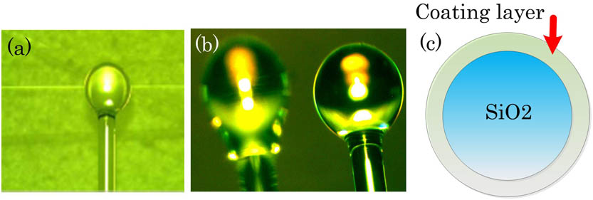
Fig. 1. Tapered fiber-microsphere coupling system: (a) photo of the coupling system; (b) microspheres fabricated by using the CO 2
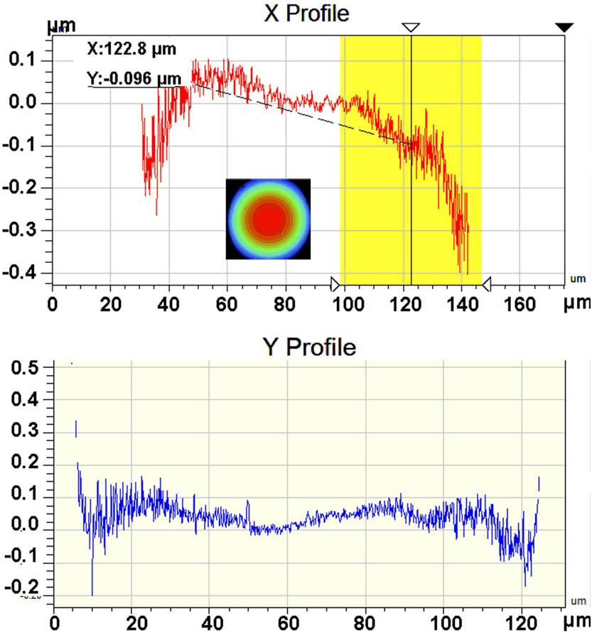
Fig. 2. Measured surface topography of the SiO 2 R a = 30 nm
Fig. 3. Measured WGM transmission spectra of the SiO 2 D ≈ 359 μm d ≈ 3 μm bandwidth ≈ 1.2 pm D ≈ 371 μm d ≈ 3 μm bandwidth ≈ 2.4 pm
Fig. 4. Tunable WGM transmission spectra (a) varies with different pump powers, where the respective peak wavelength is given in (b), and shows a blue-shift for the decreased pump power.
Fig. 5. Experimental setup of the single-wavelength fiber ring laser based on the tapered fiber-microsphere coupling system.
Fig. 6. Mode-hopping-free single-wavelength laser spectra measured for two hours.
Fig. 7. Measured tunable laser spectra. With the pump power decreased, the laser wavelength is blue-shifted.
Fig. 8. Mode distribution (a) in the SiO 2
Fig. 9. Comparison of the WGM transmission spectra with (a) d = 0.22 μm n = 2.0 d = 0.14 μm n = 2.0 n = 2.4 d = 0.1
Fig. 10. Mode distribution in the HM with a coating thickness of 0.27 μm and a refractive index of 2.5: (a) under coupling with a gap of 0.6 μm, (b) critical coupling with a gap of 0.3 μm, and (c) over coupling with a gap of 0 μm.

Set citation alerts for the article
Please enter your email address
© Copyright 2018-2021 | Chinese Laser Press. All Rights Reserved 沪ICP备15018463号-20