Hongdan Wan, Hongye Li, Haohan Zhu, Ji Xu, Yunqing Lu, Jin Wang. Tunable, ultra-narrow-band optical filter based on a whispering gallery mode hybrid-microsphere[J]. Chinese Optics Letters, 2016, 14(11): 112302
Copy Citation Text
We demonstrate an ultra-narrow-band optical filter based on a hybrid-microsphere consisting of a coated microsphere. As compared to the microsphere, the hybrid-microsphere produces a quality factor of , a transmission spectrum bandwidth of , and an increased side-mode suppression ratio. The microsphere surface roughness and whispering gallery mode (WGM) transmission spectra are measured experimentally. A 0.01 nm bandwidth, single-wavelength fiber laser output is achieved with a tunable wavelength, using the microsphere as the mode selector. The optical field distribution and WGM transmission spectrum of the hybrid-microsphere with different coating parameters are theoretically investigated by the finite-difference time-domain method.
As applied in optical sensing and communication systems, narrow-linewidth fiber lasers are of great interest for development because of their high coherence, flexible wavelength, and compact structure[1,2]. Fiber filters for narrow-bandwidth laser mode selection are usually realized with fiber gratings, saturable absorbers, Fabry–Pérot (FP) cavities, etc[3–5], where their bandwidth is usually broader than 1 GHz. Various cavities including the FP cavity, the whispering gallery mode (WGM) cavity, and the polarization controller (PC) cavity are presented[6–8], especially since a novel scheme of the integrated FP cavity using graphene has been recently reported[9,10]. The major advantages of WGM resonators compared with the FP are a small size, a large wavelength range where WGM resonators have high quality () factors, and low sensitivity to mechanical noise[11]. Recently, an ultra-narrow-band mode selection method based on a high () WGM cavity microsphere is proposed[12]. A single-mode laser output with a 650 Hz bandwidth is obtained at 1550 nm. However, manufacturing such a microsphere out of a crystal is time and labor consuming. Compared to the microsphere, the microsphere can be easily fabricated by utilizing the surface tension effect. However, the factor of microsphere is prone to be reduced due to the ellipse asymmetry and the surface contamination[13]. Therefore, new methods are needed to improve the cavity of microspheres.
This Letter proposes a new type of WGM hybrid-microsphere (HM), which consists of a microsphere coated with a high refractive index layer on the surface. Based on the total light reflection, the WGM mode is confined inside the cavity, where the scattering loss and radiation loss can be reduced. Thus, the side-mode suppression ratio is increased, the bandwidth of the WGM transmission spectrum is compressed, and a high factor is achieved. The mode distribution in the HM is also investigated based on the finite-difference time-domain (FDTD) method. The WGM transmission spectra with different coating parameters, namely the refractive index and the layer thickness, are analyzed. Also, a single-wavelength fiber ring laser based on the WGM microsphere is demonstrated.
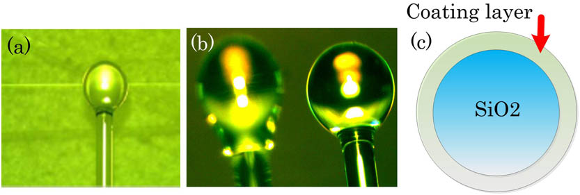
Figure 1 shows the theoretical model and the photo of the tapered fiber-microsphere coupling system. The tapered fiber is made from a single-mode fiber, heated by a Hydroxide flame. Its diameter is controlled to 3–5 μm. The arc discharging and laser heating methods are used to fabricate the microsphere, while the latter has better circular symmetry and surface homogeneity, being preferred for achieving a higher factor.
Sign up for Chinese Optics Letters TOC. Get the latest issue of Chinese Optics Letters delivered right to you!Sign up now
Figure 1.Tapered fiber-microsphere coupling system: (a) photo of the coupling system; (b) microspheres fabricated by using the laser heating method (right, diameter of 300 μm) and by using the arc discharging method (left, diameter of 200 μm); (c) structure of the HM.
As it has been validated by previous reports, the factor of a microsphere mainly depends on the surface roughness[14,15], while the scattering loss and absorption loss of the microsphere can be ignored, because the diameter is larger than 300 μm, and the absorption coefficient is small near the infrared wavelength[14]. Figure 2 shows the surface topography of the microsphere measured experimentally using a three-dimensional (3D) white light interferometer (Veeco). Compared to the atomic force microscope (AFM) method, the surface profiles of our microspheres are measured in a nondestructive testing manner. The factor can be calculated according to Ref. [15]. is the measured surface roughness, which mainly decides the WGM transmission scattering loss in the microsphere. The axis and axis of the “X profile” and the “Y profile” represent the detection vision-field size of the 3D white light interferometer. The surface roughness decides the optical scattering loss and affects the factor of the microsphere. near the meridian plane is , so the factor can reach under an optimized coupling condition.
Figure 2.Measured surface topography of the microsphere with a surface roughness of .
The WGM transmission spectra of the microsphere are measured experimentally, as shown in Fig. 3. The microsphere has a diameter of and 371 μm. The tapered fiber diameter is fixed to about 3 μm. The pump source is a narrow-band tunable laser (Agilent 81960A). Dips of more than 90% of the off-resonance transmission were observed when we used the sphere with under an over-coupling condition. The amplitude of the dip depends on the alignment of the fiber and the sphere as well as on the particular mode being excited[16]. The highest factor is measured to be , the narrowest 3 dB bandwidth is 1.2 pm near 1549.45 nm for , and the 3 dB bandwidth is 2.4 pm near 1549.52 nm for . The measured factor is lower than the simulated one due to the environmental contamination as well as the instability of the coupling condition.
Figure 3.Measured WGM transmission spectra of the microsphere with (a) and , where the 3 dB . (b) and , where the 3 dB .
It is observed that the peak wavelength of the WGM transmission spectrum is tunable by varying the pump power, as shown in Fig. 4(a). The pump power is tuned by a variable optical attenuator. A 12 dB decreasing of the pump power results in a wavelength blue-shift of 5 pm, as shown in Fig. 4(b).
Figure 4.Tunable WGM transmission spectra (a) varies with different pump powers, where the respective peak wavelength is given in (b), and shows a blue-shift for the decreased pump power.
Then, based on the tapered fiber-microsphere coupling system, a single-wavelength fiber ring laser was proposed and demonstrated. The configuration of the fiber laser is shown in Fig. 5. A 980 nm pump laser diode (LD) is coupled to an erbium-doped fiber (EDF) with a length of 0.5 m by a wavelength division multiplexing (WDM). The microsphere is coupled into the ring cavity by the tapered fiber. The PC is used to control the intracavity polarization state. The isolator (ISO) is used to ensure unidirectional operation. An optical coupler is used to offer feedback and laser output for detection with a 10% feedback into the ring cavity and a 90% output, and it is measured by an optical spectrum analyzer.
Figure 5.Experimental setup of the single-wavelength fiber ring laser based on the tapered fiber-microsphere coupling system.
Figure 6 shows the stable single-wavelength laser spectra measured for 2 h with a 3 dB bandwidth of about 0.01 nm and a side-mode suppression ratio of 39 dB. No mode hopping happens during the experiments.
Figure 6.Mode-hopping-free single-wavelength laser spectra measured for two hours.
The peak wavelength of the fiber ring laser is tunable, as shown in Fig. 7. With power of the pump LD decreased, the laser wavelength shifts to a shorter wavelength. A pump power variation of 150 mW results in a wavelength change of 0.05 nm. The reason for the shift of the wavelength is that the microsphere temperature is increased when the pump power increases, as more optical energy is stored in the microsphere. The change of wavelength can be calculated using following equation[17]: where is the change of the wavelength, is the resonant wavelength of the transmission spectrum, is the temperature change, is the microcavity refractive index, is the thermo-optic coefficient, and is the thermo-expansion coefficient.
Figure 7.Measured tunable laser spectra. With the pump power decreased, the laser wavelength is blue-shifted.
As to the increase the factor of , the HM structure shown in Fig. 1(b) is proposed and analyzed. Under the same coupling condition, a different WGM distribution in the microsphere and the HM are simulated using the FDTD method and shown in Figs. 8(a) and 8(b), where the operation wavelengths are 1556.89 and 1549.83 nm. The sudden reduction of the output power happens if light is coupled into the microsphere through the fiber taper, and with the WGM oscillating in the microsphere, a higher factor results in a lower output power and a higher intracavity power.
Figure 8.Mode distribution (a) in the microsphere and (b) in the HM (the layer’s refractive index is 2.5, and the layer thickness is 0.14 μm), where the coupling condition and the sphere radius are fixed. (c) Comparison of the WGM transmission spectra.
Figure 8 shows that adding a high refractive index layer increases the factor, and coating a high refractive index layer on the microsphere increases the refractive index difference, improves the total light reflection confinement, and pushes the WGM mode into the coating layer. The scattering loss and radiation loss are then reduced. The WGM transmission spectra of two microsphere cavities at the same coupling condition are compared in Fig. 8(c), where the gap between the tapered fiber and the microsphere is set to 0.15 μm.
The HM produces a WGM transmission spectrum with a narrower bandwidth and a higher side-mode suppression ratio. The calculated factor of the HM is also 50 times larger than that of the microsphere, providing an improved narrow-band mode selection capability. The simulation of adding a high refractive index layer shows that under an optimized coupling condition, we can achieve a factor of and a narrow bandwidth of . Experimentally, the high refractive index material we used and coated on the is a sol-gel film of . The coating method is the dip coating method.
For a pump wavelength ranging from 1.3–1.7 μm, Figs. 9(a) and 9(b) show the WGM transmission spectra with a different refractive index from to 2.5, where the coating layer thickness is fixed to 0.22 and 0.14 μm, respectively. The side-mode suppression ratio is higher, and the bandwidth is narrower for . The WGM transmission spectra with a layer thickness from 0.1 to 0.22 μm are compared and shown in Fig. 9(c). The refractive index of the layer material remains 2.4. For a layer thickness of 0.22 μm, the bandwidth is narrower, and the side-mode suppression ratio is higher. Thus, for a specific pump wavelength and microsphere size, the refractive index and thickness of the coating layer could be further optimized to achieve a much narrower bandwidth and a much higher side-mode suppression ratio.
Figure 9.Comparison of the WGM transmission spectra with (a) , where the layer refractive index is , 2.1, 2.2, 2.3, and 2.5; (b) , where the layer refractive index is , 2.1, 2.2, 2.3, and 2.5; and (c) , where the layer thickness is , 0.14, 0.18, 0.22, and 0.26 μm.
The mode distribution of the WGM in the HM with a different coupling gap to the tapered fiber is simulated in Fig. 10. However, it is not easy to control the coupling gap between the fiber and the microsphere with the precision of a nanometer. So, in our experiments, we keep the microsphere attached to the fiber taper, and the high-order WGM modes appear, as shown in Fig. 3. The critical coupling condition is achieved with a gap of 0.3 μm, as shown in Fig. 10(b).
Figure 10.Mode distribution in the HM with a coating thickness of 0.27 μm and a refractive index of 2.5: (a) under coupling with a gap of 0.6 μm, (b) critical coupling with a gap of 0.3 μm, and (c) over coupling with a gap of 0 μm.
In conclusion, this Letter presents a theoretical analysis of the WGM in the HM with a high refractive index layer coated on the microsphere. The calculated factor of the HM is 50 times higher than that of the microsphere. By using a 3D white light interferometer, the surface roughness of the microsphere is measured to be 30 nm, with a factor of about . The factor of the tapered fiber-microsphere coupling system is , and the 3 dB bandwidth of the WGM spectrum is 1.2 pm. A single-wavelength fiber laser output with a 3 dB bandwidth of 0.01 nm is achieved by using a microsphere as the narrow-band mode selector. The laser wavelength is optically tunable by changing the power of the pump LD. The proposed HM provides an effective method for ultra-narrow-band optical filtering and will have potential applications in optical sensor and fiber laser systems.
Hongdan Wan, Hongye Li, Haohan Zhu, Ji Xu, Yunqing Lu, Jin Wang. Tunable, ultra-narrow-band optical filter based on a whispering gallery mode hybrid-microsphere[J]. Chinese Optics Letters, 2016, 14(11): 112302