• Acta Optica Sinica
  • Vol. 38, Issue 5, 0512002 (2018)
Xiaoliu Li1, Hua Shen1、2、*, Jia Li1、2, Xueyan Zhu1, Dechao Yao1, Qing Lu1、2, and Rihong Zhu1、2
Author Affiliations
  • 1 School of Electronic and Optical Engineering, Nanjing University of Science and Technology, Nanjing, Jiangsu 210094, China
  • 2 MIIT Key Laboratory of Advanced Solid Laser, Nanjing University of Science and Technology, Nanjing, Jiangsu 210094, China
  • show less
    DOI: 10.3788/AOS201838.0512002 Cite this Article Set citation alerts
    Xiaoliu Li, Hua Shen, Jia Li, Xueyan Zhu, Dechao Yao, Qing Lu, Rihong Zhu. Optical Path Difference Calibration Method of Optical Fiber Array Point Source Generator in Tilted-Wave-Interferometer[J]. Acta Optica Sinica, 2018, 38(5): 0512002 Copy Citation Text show less
    TWI system based on point source array
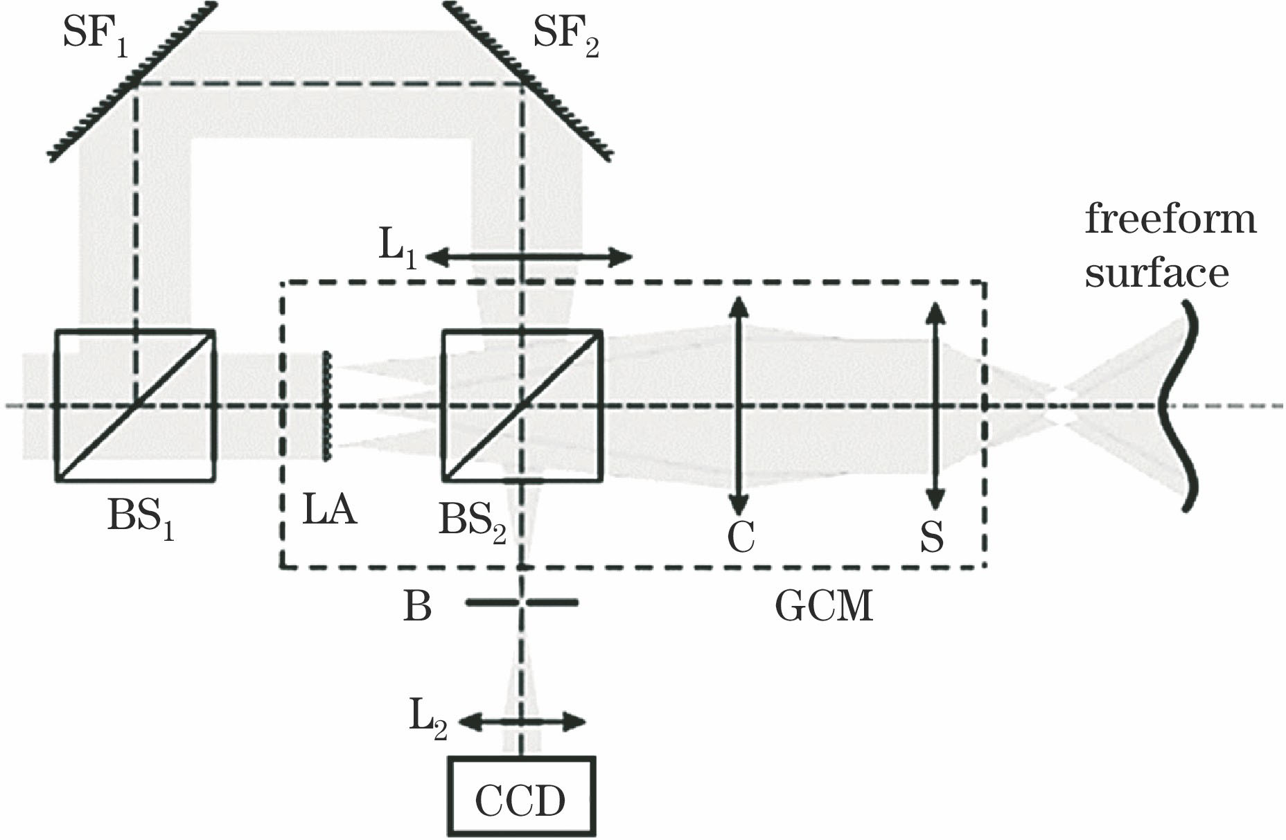
    Fig. 1. TWI system based on point source array
    Schematic of point source generator structure
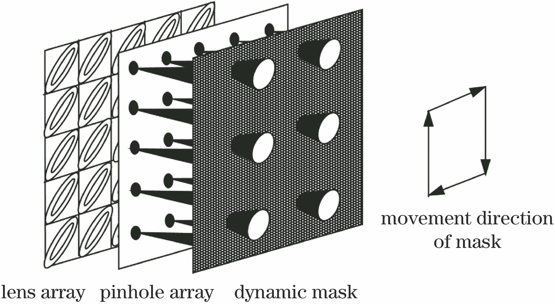
    Fig. 2. Schematic of point source generator structure
    Schematic of point source generator structure based on fiber array
    Fig. 3. Schematic of point source generator structure based on fiber array
    Influence of optical path difference between output light beams on detection result
    Fig. 4. Influence of optical path difference between output light beams on detection result
    Schematic of phase difference detection system
    Fig. 5. Schematic of phase difference detection system
    Diagram of experimental setup
    Fig. 6. Diagram of experimental setup
    Light path schematic for measurement of parabolic mirror using ZYGO interferometer
    Fig. 7. Light path schematic for measurement of parabolic mirror using ZYGO interferometer
    (a) Surface deviation result of measurement of parabolic mirror using TWI system; (b) surface deviation result of measurement of parabolic mirror using ZYGO interferometer
    Fig. 8. (a) Surface deviation result of measurement of parabolic mirror using TWI system; (b) surface deviation result of measurement of parabolic mirror using ZYGO interferometer
    Wavelength /nmRefractive indexu1 /mVu2 /mVu3 /mVΔφRange of m
    λ1=450.0n1=1.47631.633.720.30.200m1∈[3870.3,4001.5]
    λ2=532.0n2=1.471207.4275.0152.00.090m2∈[3262.7,3373.3]
    λ3=632.8n3=1.4671700.02120.01360.00.085m3
    Table 1. Fiber measurement data at (-1,1) in fiber array
    Y /mmδ
    X=-1.0 mmX=-0.5 mmX=0 mmX=0.5 mmX=1.0 mm
    1.02515.68λ3-2889.66λ3-1920.33λ31255.27λ3660.93λ3
    0.5-2281.08λ31171.92λ3-898.39λ32623.69λ32089.07λ3
    01781.75λ32967.72λ30-2495.67λ31469.12λ3
    -0.5-2125.04λ31498.45λ3-2786.42λ3-2391.14λ3468.26λ3
    -1.0984.68λ32319.05λ3-2610.70λ32416.76λ3-1136.46λ3
    Table 2. Optical path difference of each beam in point source generator with fiber array relative to reference beam
    Xiaoliu Li, Hua Shen, Jia Li, Xueyan Zhu, Dechao Yao, Qing Lu, Rihong Zhu. Optical Path Difference Calibration Method of Optical Fiber Array Point Source Generator in Tilted-Wave-Interferometer[J]. Acta Optica Sinica, 2018, 38(5): 0512002
    Download Citation