
Ziming Dong, Yanan Zhang, Zhigang Liu, Xiang Jiao, Jianqiang Zhu, Wenhui Cui, Weiheng Lin. Eccentric Dual-Rotor Polishing and the Suppression of Mid-Spatial-Frequency Error: Technological Study[J]. Chinese Journal of Lasers, 2021, 48(24): 2404002
- Chinese Journal of Lasers
- Vol. 48, Issue 24, 2404002 (2021)
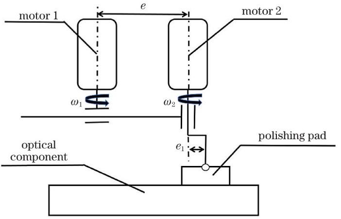
Fig. 1. Motion diagram of eccentric dual-rotor
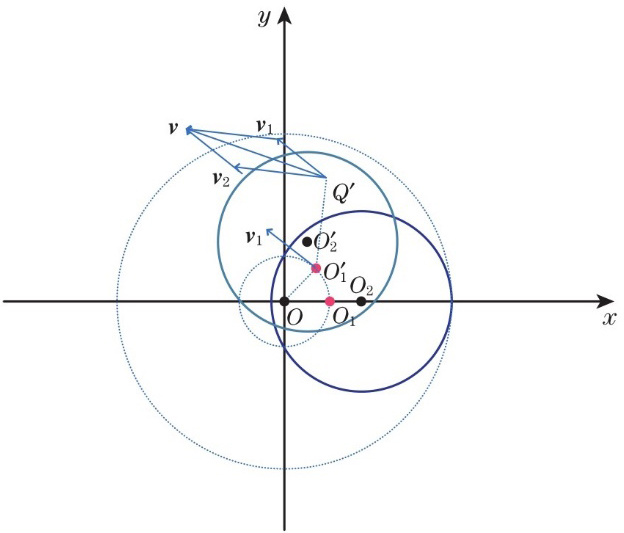
Fig. 2. Motion analysis of eccentric dual-rotor
Fig. 3. Cross-section fitting diagram of parameter matrix
Fig. 4. Shapes of removal function when R2<0.995. (a) Layering, e1=5/6, e=4/3, R2=0.9875; (b) central inferior concave, e1=0.5, e=4/3, R2=0.9551; (c) Gaussian-like, e1=0.3, e=5/12, R2=0.9931; (b) flat top, e1=11/12, e=1/3, R2=0.9859
Fig. 5. Parameters diagram with R2>0.995
Fig. 6. Fitting result and trajectory diagram when n=-1/3 (e1=0.5, e=0.5, R2=0.9939). (a) Fitting result; (b) trajectory diagram
Fig. 7. Fitting result and trajectory diagram when n=-4/5 (e1=0.25, e=1, R2=0.9959). (a) Fitting result; (b) trajectory diagram
Fig. 8. Simulation diagram of direction removal characteristic. (a) Removal function of dual-rotor motion; (b) removal function of eccentric dual-rotor motion
Fig. 9. Five-link-double-swing polishing system
Fig. 10. Dual-rotor removal function interferogram and fitting results. (a) Interferogram; (b) shape of removal function on Metropro software; (c) three-dimensional model; (d) fitting result
Fig. 11. Surface shape interferograms of eccentric dual-rotor removal function and shapes of corresponding removal function. (a) e=2.76; (b) e=3.24; (c) e=5.91; (d) e=6.12
Fig. 12. Normalized eccentric dual-rotor removal function and normalized cross-section Gaussian fitting diagrams. (a) e=2.76; (b) e=3.24; (c) e=5.91; (d) e=6.12
Fig. 13. Overlay error curves under different grating intervals
Fig. 14. Partially enlarged interferograms of workpieces 2 and 3. (a) Workpiece 2, dual rotor motion; (b) workpiece 3, eccentric dual-rotor motion
Fig. 15. Local surface curves of workpieces 2 and 3. (a) Workpiece 2, dual rotor motion; (b) workpiece 3, eccentric dual-rotor motion
Fig. 16. PSD analysis diagrams of workpieces 2 and 3. (a) Workpiece 2, dual rotor motion; (b) workpiece 3, eccentric dual-rotor motion
| ||||||||||||||||||||||||||
Table 1. Removal function parameters in the simulation of direction removal characteristic
| ||||||||||||||||||||
Table 2. Simulated direction removal characteristic of removal function
| |||||||||||||||||||||||||||||||||||||||||||||||||||||||||||||||||
Table 3. Removal function parameters of fixed-point polishing experiment

Set citation alerts for the article
Please enter your email address
© Copyright 2018-2021 | Chinese Laser Press. All Rights Reserved 沪ICP备15018463号-20