• Chinese Optics Letters
  • Vol. 17, Issue 9, 092201 (2019)
Yuting Deng, Guofan Jin, and Jun Zhu*
Author Affiliations
  • State Key Laboratory of Precision Measurements Technology and Instruments, Department of Precision Instrument, Tsinghua University, Beijing 100084, China
  • show less
    DOI: 10.3788/COL201917.092201 Cite this Article Set citation alerts
    Yuting Deng, Guofan Jin, Jun Zhu. Design method for freeform reflective-imaging systems with low surface-figure-error sensitivity[J]. Chinese Optics Letters, 2019, 17(9): 092201 Copy Citation Text show less
    Optical-path-length change caused by figure errors.
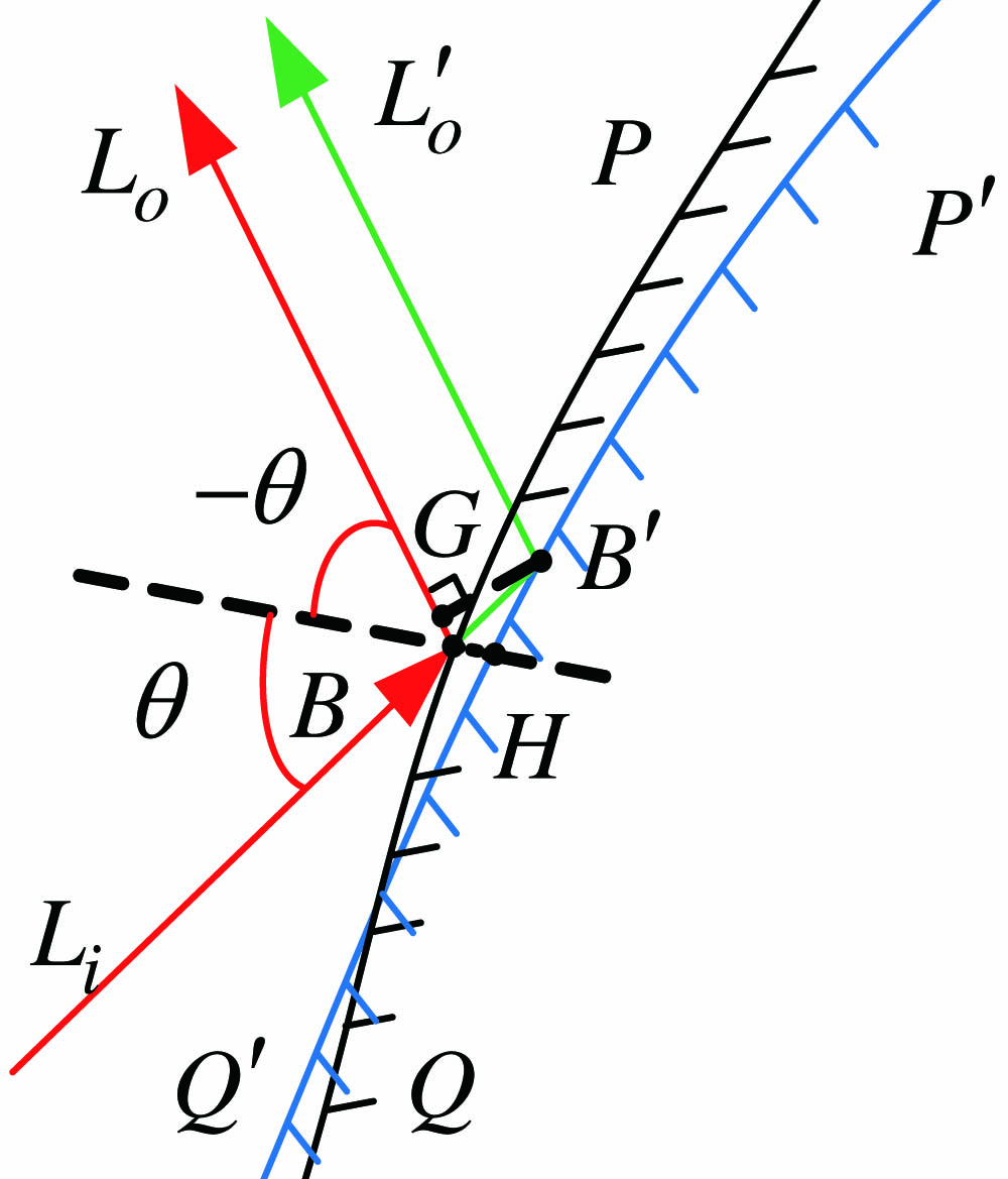
    Fig. 1. Optical-path-length change caused by figure errors.
    Establish initial planar system.
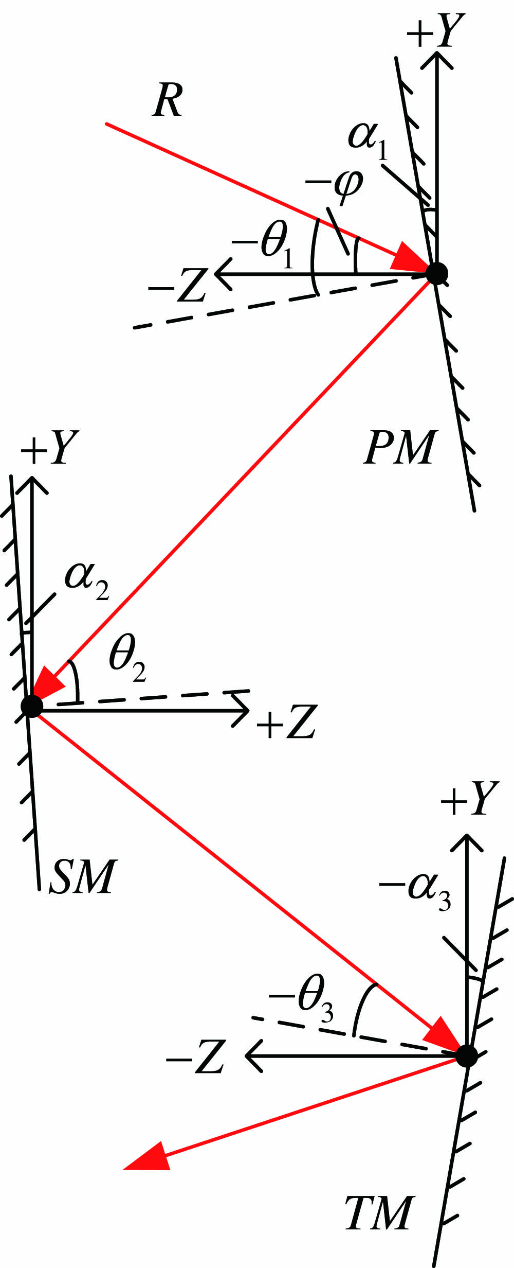
    Fig. 2. Establish initial planar system.
    (a) Forward ray tracing; (b) reverse ray tracing.
    Fig. 3. (a) Forward ray tracing; (b) reverse ray tracing.
    Shifting image points to change AOIs on the TM.
    Fig. 4. Shifting image points to change AOIs on the TM.
    (a) Initial planar system; (b) initial freeform surfaces system; (c) freeform surfaces system with |θ1| greater than w1; (d) freeform surfaces system, in which |θ1|, |θ2| are greater than w1, w2, respectively; (e) initial system with low surface-figure-error sensitivity, in which |θ1|, |θ2|, and |θ3| are greater than w1, w2, and w3, respectively; (f) optimized system; (g) field map of the RMSWFE.
    Fig. 5. (a) Initial planar system; (b) initial freeform surfaces system; (c) freeform surfaces system with |θ1| greater than w1; (d) freeform surfaces system, in which |θ1|, |θ2| are greater than w1, w2, respectively; (e) initial system with low surface-figure-error sensitivity, in which |θ1|, |θ2|, and |θ3| are greater than w1, w2, and w3, respectively; (f) optimized system; (g) field map of the RMSWFE.
    (a) Initial planar system; (b) initial system designed by CI-3D method; (c) optimized system; (d) field map of the RMSWFE.
    Fig. 6. (a) Initial planar system; (b) initial system designed by CI-3D method; (c) optimized system; (d) field map of the RMSWFE.
    Sensitivity curve of the two systems to surface figure errors. (a) PM; (b) SM; (c) TM.
    Fig. 7. Sensitivity curve of the two systems to surface figure errors. (a) PM; (b) SM; (c) TM.
    ParameterSpecification
    Field of view (FOV)3°×4°
    F-number1.5
    Focal length100 mm
    Wavelength8–12 μm
    Table 1. Optical System Specifications
    SystemAOIPMSMTM
    (a)Min302525
    (b)Min28.3421.6619.25
    (c)Min30.3622.4919.64
    (d)Min30.3625.4621.60
    (e)Min30.3625.4625.62
    (f)Min43.5851.7526.27
    Table 2. Absolute AOIs on Each Surface of the Systems in Fig. 5a
    Yuting Deng, Guofan Jin, Jun Zhu. Design method for freeform reflective-imaging systems with low surface-figure-error sensitivity[J]. Chinese Optics Letters, 2019, 17(9): 092201
    Download Citation