• Acta Optica Sinica
  • Vol. 38, Issue 12, 1215010 (2018)
Minyang Wu1、*, Jianjun Guo2, and Ming Jiang2、*
Author Affiliations
  • 1 School of Mathematics and Physics, Suzhou University of Science and Technology, Suzhou, Jiangsu 215009, China
  • 2 School of Civil Engineering, Suzhou University of Science and Technology, Suzhou, Jiangsu 215009, China
  • show less
    DOI: 10.3788/AOS201838.1215010 Cite this Article Set citation alerts
    Minyang Wu, Jianjun Guo, Ming Jiang. Calibration Method of Microscopic Three-Dimensional Digital Image Correlation System Based on Fixed-Point Rotation[J]. Acta Optica Sinica, 2018, 38(12): 1215010 Copy Citation Text show less
    Microscopic three-dimensional digital image correlation system
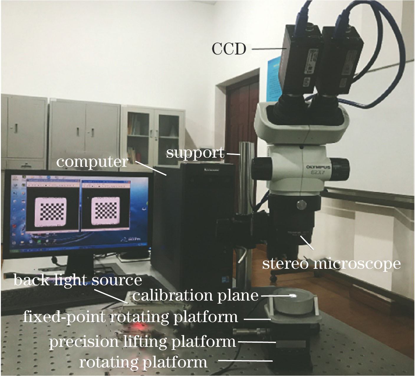
    Fig. 1. Microscopic three-dimensional digital image correlation system
    Chess board calibration plate
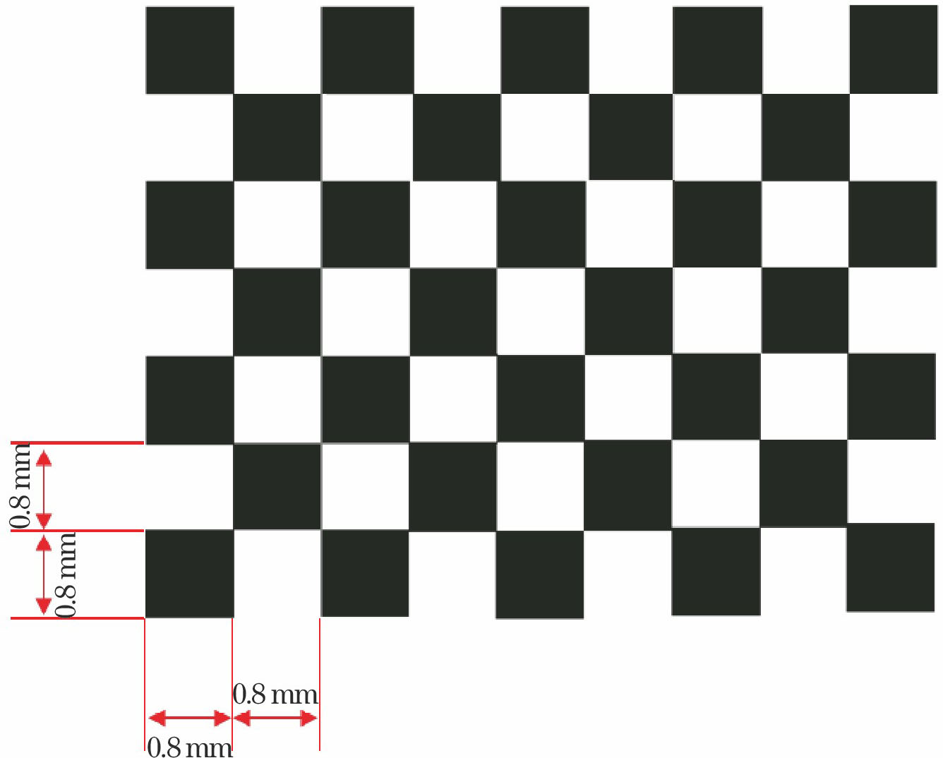
    Fig. 2. Chess board calibration plate
    Fixed-point rotation platform. (a) CAD diagram; (b) physical drawing
    Fig. 3. Fixed-point rotation platform. (a) CAD diagram; (b) physical drawing
    Optical path of stereo microscope
    Fig. 4. Optical path of stereo microscope
    Relationship between inclination angle and depth of field
    Fig. 5. Relationship between inclination angle and depth of field
    Process of image acquisition of calibration plate. (a) Fixed-point rotation of calibration plate; (b) image acquisition of calibration plate (left CCD)
    Fig. 6. Process of image acquisition of calibration plate. (a) Fixed-point rotation of calibration plate; (b) image acquisition of calibration plate (left CCD)
    Schematic of main point calibration. (a) Calibration images under different magnification; (b) fitting of projection point coordinates
    Fig. 7. Schematic of main point calibration. (a) Calibration images under different magnification; (b) fitting of projection point coordinates
    Main point coordinates for 22 times calibration
    Fig. 8. Main point coordinates for 22 times calibration
    Reprojection errors
    Fig. 9. Reprojection errors
    Rotation angle of calibration plate around Z axis when intervals of calibration plate rotation around Z axis are 5°, 10° and 15°, respectively. (a) Left sub optical path; (b) right sub optical path
    Fig. 10. Rotation angle of calibration plate around Z axis when intervals of calibration plate rotation around Z axis are 5°, 10° and 15°, respectively. (a) Left sub optical path; (b) right sub optical path
    Relative translation quantities of left and right sub optical paths. (a) Calibration plate rotating around Z-axis with 5°; (b) calibration plate rotating around Z-axis with 10°
    Fig. 11. Relative translation quantities of left and right sub optical paths. (a) Calibration plate rotating around Z-axis with 5°; (b) calibration plate rotating around Z-axis with 10°
    Overall errors of calibration board under different attitudes
    Fig. 12. Overall errors of calibration board under different attitudes
    Influence of attitude number of right CCD on stability of calibration results. (a) Focal length versus attitude number; (b) main point coordinate versus attitude number; (c) radial distortion coefficient versus attitude number; (d) relative error versus attitude number
    Fig. 13. Influence of attitude number of right CCD on stability of calibration results. (a) Focal length versus attitude number; (b) main point coordinate versus attitude number; (c) radial distortion coefficient versus attitude number; (d) relative error versus attitude number
    Three-dimensional average displacement vector
    Fig. 14. Three-dimensional average displacement vector
    Picture of coin
    Fig. 15. Picture of coin
    Coin speckle maps from left and right CCDs. (a) Left CCD; (b) right CCD
    Fig. 16. Coin speckle maps from left and right CCDs. (a) Left CCD; (b) right CCD
    Three-dimensional shape measurement chart of coin
    Fig. 17. Three-dimensional shape measurement chart of coin
    Magnification0.811.251.622.53.2455.6
    Field of view x /mm15.713.010.18.16.55.24.03.22.62.3
    Field of view y /mm13.210.98.56.85.44.33.42.72.21.9
    Depth of field /mm2.5201.3800.8810.4900.4340.2440.2000.1290.1000.087
    Table 1. Depths of field and fields of view under different magnification
    CCDfx/pixelfy/pixelu0/pixelv0/pixelk1/10-2
    Left CCD8076.518276.641223.751026.612.8
    Right CCD8071.948276.071224.191024.783.2
    Relative error /%0.0290.0200.1660.1660.530
    Table 2. Internal parameters
    Magnification(3,4)(3,5)(4,4)(4,5)
    x /pixely /pixelx /pixely /pixelx /pixely /pixelx /pixely /pixel
    0.81276.121096.651281.101474.081655.771090.191661.061469.81
    1.01263.611078.291267.421379.601565.051074.771569.101376.05
    1.251253.961065.851256.931306.721494.751063.101497.951303.89
    1.61246.741055.621248.891243.271434.141053.421436.641240.87
    2.01241.041048.461243.021198.271390.511046.681392.601196.32
    2.51236.401043.661238.111165.871358.331042.211359.801164.43
    Line fittingy=1.3004x-564.9919y=7.2x-7789.3y=0.1619x+821.5713y=1.0159x-218.0002
    Table 3. Line fitting table
    CCDσx/pixelσy/pixelfx/pixelfy/pixelu0/pixelv0/pixel
    Left CCD0.110.1023186.9223189.271225.891023.75
    Right CCD0.110.1023187.5823189.191226.271024.16
    Table 4. Internal parameter calibration results of CCD
    Point No.12345678
    Maximum deviation /μm0.770.530.650.830.70.360.670.71
    Average relative error /%2.62.21.92.13.01.42.02.3
    Mean square error /μm0.490.490.310.270.340.420.230.32
    Table 5. Measurement results for movement in Z direction
    Minyang Wu, Jianjun Guo, Ming Jiang. Calibration Method of Microscopic Three-Dimensional Digital Image Correlation System Based on Fixed-Point Rotation[J]. Acta Optica Sinica, 2018, 38(12): 1215010
    Download Citation