Abstract
Recently, the perfect vector (PV) beam has sparked considerable interest because its radius is independent of the topological charge (TC), which has demonstrated special capabilities in optical manipulation, microscopy imaging, and laser micromachining. Previous research about the generation and manipulation of such PV beams only focuses on the linear optical fields. Therefore, the generation of nonlinear PV beams is still lacking. Here, we propose a dual waveband generator to simultaneously generate the PV beams in linear and nonlinear wavebands. In our experiment, PV beams with different polarization states are realized. It is proved that the polarization states of the generated PV beams can be flexibly adjusted by changing the axis direction of a half wave plate. The experimental results show that the radii of the generated PV beams are equal and independent of the TCs. With proper alteration of the nonlinear crystals, this approach could be further extended to other nonlinear processes, such as sum-frequency generation and difference-frequency generation.1. INTRODUCTION
Vector beams with space-varying polarization distributions are the solution of the vector paraxial wave equation. From a historical perspective, research on the vector optical field can be traced back to fifty years ago [1]. Ever since the original concept was first pioneered by Snitzer [1], vector optical beams have attracted tremendous attention and academic interest because of their potential applications in various research realms, such as super-resolution imaging [2], optical trapping [3,4], and laser micromachining [5,6]. Prominent paradigms of vector optical beams are radially and azimuthally polarized beams. Due to the sharply focused light below the diffraction limit, radially polarized beams have attracted a great deal of interest in laser machining [7,8] and particle acceleration [9,10]. On the contrary, the azimuthally polarized beam can induce a strong longitudinal magnetic field, which provides potential application in probing magnetic interactions [2,11]. Besides their applications in classical optics, unusual attributes of the vector beams are especially interesting in quantum mechanics foundations such as generating novel cluster states [12] and quantum memory [13]. Motivated by those applications, a variety of methods have been used to generate the vector optical beams. One direct way is by utilizing a Yb fiber laser incorporating an intracavity axicon [14] or a conical Brewster prism [15]. The indirect methods employed to generate the vector optical beams are shaping the wavefront with the aid of spatial light modulators [16–19], metasurfaces [20], -plates [21,22], digital micromirror devices [23], and so on. However, the intensity profile or the radius of the traditional vector beams is strongly dependent on the absolute value of topological charge (TC), which makes it difficult to couple into a fiber. Besides, for the vector beam optical manipulation fields, the radius changing of the traditional vector beams with different TC is also not a stable way to control the particles’ trajectory. Recently, considerable attention was paid to the generation of the perfect vector (PV) and elliptic PV beams, where the radius of the intensity profile is independent of the TC [22,24–28]. Based on the digitalized geometric phases [22], the dynamic modulation of the geometric phases [24,25], and the phase elements and interferometer [26,27], PV beams are generated successfully in the experiment. However, all these methods are actually conducted in linear optics. The generation and manipulation of such PV beams in nonlinear optical fields are still lacking. Recently, nonlinear generation and manipulation of vector beams in frequency conversion processes have been successfully implemented both in experimental and simulated environments [19,29].
In this study, we propose a method to generate the PV beams both in a fundamental frequency (FF) and a second harmonic (SH) wavebands at the same time. In our experiment, PV beams with different polarization states are generated. In addition, we measure the vectorial properties of the generated PV beams by adding a Glan–Taylor (GT) prism before the charge coupled device (CCD). The experiment results are consistent with the theoretical simulations. Moreover, the results demonstrated that the radii of the generated PV beams are equal both in linear and nonlinear wavebands which are independent of the TC.
2. EXPERIMENTAL SETUP
The experimental setup is illustrated in Fig. 1. The high-energy diode-pumped all-solid-state -switched laser system delivers linearly polarized 10 ns pulses at a central wavelength of 1064 nm and operates at a 1 kHz repetition. A GT prism is used to adjust the FF beam to the horizontal polarization. A half wave plate (HWP) and a quarter wave plate () with its fast axis arranged along 45° with respect to the horizontal direction are employed to adjust the polarization state of the FF wave. The FF wave is split into two orthogonal directions by a polarized beam splitter (PBS). Three mirrors (, , ) and a spiral phase plate (SPP) are composed of a Sagnac interferometer. The SPP is located at the place where two separated beams have same optical length before incident into it. Two orthogonal beams are recombined by a PBS after which the FF wave can be expressed in the form of where represents the FF wave. and refer to the amplitude and TC of the FF wave, respectively. describes the azimuthal angle, and is the phase difference. denotes the angle between the fast axis of HWP and the horizontal direction. After passing through an axicon whose base angle is 2°, the Bessel beam in the cylindrical coordinate system is generated, which can be written as where refers to the first kind of Bessel function. and , respectively, refer to the wave vectors along radial and propagation directions and satisfy the relationship of , where is the wavelength of the incident FF wave. Theoretically, the perfect vortex beam is the Fourier transformation of a Bessel Gaussian beam [30]. Therefore, a lens () placed before with focus length () of 200 mm is employed to perform the Fourier transformation in our experiment. According to the property of the Fourier transformation and the orthogonality of the Bessel functions, the form of the FF wave in the polar coordinate system can be derived as Another with a fast axis along is employed to convert the two linearly polarized beams into PV beams, which can be simplified as Using the method proved above, the PV beam at the FF waveband is generated. In order to generate nonlinear PV beams, two cascading nonlinear crystals are inserted between the axicon and the dichroic mirror (DM). Both samples (S) are 5% (mole fraction) crystals, and they are placed in two orthogonal directions. Under the undepleted pump and paraxial approximation, we have an equation that describes the SH optical field as where represents the generated SH beam. , , , and are, respectively, the angular frequency of the FF beam, the effective nonlinear coefficient, the light speed in vacuum, and the refractive index of the generated SH beam. In our experiment, the Type-I (oo-e) phase matching condition is satisfied. Finally, the generated SH optical field can be written as is the length of the nonlinear crystal along the propagation direction. After substituting Eq. (2) into Eq. (6), we can get After passing through a Fourier transformation lens and a , the generated SH PV beam in the polar coordinate system can be written as Here, the fast axis of the is arranged along a 45° direction with respect to the horizontal direction. At last, two spatial filters ( and ) are used to pick out the PV beams. CCDs located at the Fourier plane of the lenses and are used to record the generated PV beam. The results of generated FF and SH PV beams are, respectively, shown in Figs. 1(a) and 1(b). To make the figures vivid, we use red as the pseudo color to show the intensity distribution of the FF beam.
Sign up for Photonics Research TOC. Get the latest issue of Photonics Research delivered right to you!Sign up now
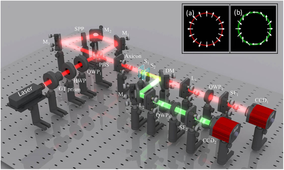
Figure 1.Schematic of the experimental setup. GT prism, Glan–Taylor prism; HWP, half wave plate; , , and , quarter wave plates; PBS, polarized beam splitter; , , , and , mirrors; SPP, spiral phase plate; and , 5% (mole fraction) ; DM, dichroic mirror; and , lens with focal length ; and , spatial filters; and , charge coupled devices. Insets (a) and (b) represent the spatial intensity and polarization distributions of the simulated FF and SH PV beams, respectively.
3. EXPERIMENTAL RESULTS AND DISCUSSION
First, the radially polarized PV beam is studied. Figure 2 displays the simulated and experimental results of the FF PV beams with TC . In this situation, the initial phase and the generated FF PV beams can be described as . Figure 2(a) theoretically describes the polarization and intensity distributions of the FF PV beam. The corresponding experimental result is presented in Fig. 2(b). To characterize the vectorial property of the PV beam, a GT prism is inserted into the optical path between and . As shown in Figs. 2(a1)–2(a9) and Figs. 2(b1)–2(b9), the intensity pattern of the PV beams changes with the polarization angle of the GT prism ranging from 0° to 160°. It is clear that when the GT prism has a polarization angle of 0°, the signal of the PV beam presents a maximum in the horizontal direction, while a minimum at the vertical position, as shown in Figs. 2(a1) and 2(b1). When the polarization angle rotates from 0° to 80°, two crescent moon patterns gradually rotate to vertical direction, as shown in Figs. 2(a1)–2(a5) and Figs. 2(b1)–2(b5). Obviously, two crescent moon patterns appear almost in the vertical direction when the polarization angle arrives at 80° and 100° for most perpendicular components parallel to the vertical directions, as shown in Figs. 2(a5), 2(a6), and Figs. 2(b5) and 2(b6). Also, as illustrated in Figs. 2(a7)–2(a9) and Figs. 2(b7)–2(b9), two crescent moon patterns rotate to the horizontal direction as well when the polarization angle of the GT prism increases. In this whole process, the extinction direction rotates along the same direction and is always perpendicular to the polarization direction of the GT prism.

Figure 2.(a) and (b) The simulated and experimental intensity distributions of the FF PV beams with TC . (a1)–(a9) Simulated intensity profile of the FF PV beams when the GT prism has different polarization angles (0°, 20°, 40°, 60°, 80°, 100°, 120°, 140°, 160°) with respect to the positive horizontal direction. (b1)–(b9) are the corresponding experimental results.
To generate the nonlinear PV beams, two orthogonal cascading nonlinear crystals with a length of 3 mm along the propagation direction of light are positioned at the Fourier plane of the axicon and lens , as shown in Fig. 1. Figure 3(a) shows the polarization and intensity distribution of the corresponding simulated result when . In this case, the generated SH PV beam can be written as . The TC of the generated SH PV beams is twice that of the FF ones owing to the Type-I (oo-e) phase matching process. The generated experimental result is shown in Fig. 3(b). The intensity pattern changes as the GT prism rotates as well. Both theoretical and experimental results are, respectively, exhibited in Figs. 3(a1)–3(a9) and Figs. 3(b1)–3(b9) as the angle of the GT prism is equal to 0°, 20°, 40°, 60°, 80°, 100°, 120°, 140°, and 160°. It can be observed that the pattern of the generated SH PV beam is split into four crescent moon patterns, and it rotates while the GT prism rotates . Moreover, we measured the intensity of the FF and SH beams corresponding to 13.5 mW and 0.05 mW, respectively. So the conversion efficiency is approximately 0.37%.
Figure 3.(a) and (b) The simulated and experimental intensity distributions of the PV beams at the SH waveband. (a1)–(a9) Simulated intensity profiles of the generated PV beams when the GT prism has different polarization angles (0°, 20°, 40°, 60°, 80°, 100°, 120°, 140°, 160°) with respect to the positive horizontal direction. (b1)–(b9) are the corresponding experimental results.
It is interesting to note that by simply rotating the axis direction of the HWP (), we can control the flexibility of the polarization states of the PV beams in a dual waveband. For simplicity and without loss of generality, two examples with and are demonstrated. In this situation, the generated FF PV beams can be, respectively, simplified as and . The corresponding SH PV beams can be written as and . Figure 4 shows the corresponding experimental results. The first and third rows depict the FF PV beams, and the corresponding SH PV beams are displayed in the second and fourth rows. Note that the generated SH PV beams are completely different from the FF ones as Type-I (oo-e) nonlinear processes occur. It is clear that the two crescent moon patterns of the FF PV beams are located at different positions while the axis direction of the HWP varies as shown in the first and third rows in Fig. 4. The direction of the crescent moon patterns rotates along the same orientation of the GT prism. At the same time, the vectorial properties of the generated SH PV beams are also changed. Four crescent moon patterns appear and rotate while the angle of the GT prism changes.
Figure 4.First and third rows are, respectively, the experimental results of the FF PV beams with and . The second and fourth rows are, respectively, the SH PV beam patterns corresponding to the FF ones. Arrows in the figures show the polarization angles (0°, 45°, 90°, 135°) of the GT prism with respect to the positive horizontal direction.
At last, we measure the radius of the generated PV beams at the focus of the lenses and , and the results are displayed in Fig. 5. It can be observed that the radii of the FF PV beams and SH PV beams are almost equal whenever the TC changes. In fact, the radius of the generated PV beam can be expressed as , where is the focus length of or , and and refer to the refractive index and base angle of the axicon, respectively. Obviously, the radius of the generated PV beams can be undoubtedly affected by the parameters of the lens and axicon. The experimental results show that the radius of the PV beams almost keep consistent with the simulated ones and are independent of the TC. In addition, we can choose proper parameters of the lens or axicon to fulfill the demand for the different radius.
Figure 5.Radii of the generated PV beams in the FF (left) and SH (right) wavebands with different TC.
In general, the method proposed above provides an alternative route to access PV beams at different wavelengths at the same time. Our studies unambiguously confirm the generation of FF and SH PV beams, which may further the generation of PV beams in ultraviolet regimes. Furthermore, this technique has potential use in other nonlinear processes such as sum-frequency generation and difference-frequency generation.
4. CONCLUSION
In summary, we propose a dual waveband generator of the PV beams and demonstrate the generation of the PV beams in FF and SH wavebands at the same time. By using this setup, the polarization states of the generated PV beams can be adjusted flexibly by rotating the axis direction of the HWP. The experimental results agree well with the simulated ones. In addition, the radii of the PV beams with different TC are measured, and the results validate that they are independent of the TC. This work provides a simple way to flexibly generate PV beams with different polarization states in a dual waveband, which may have further applications in optical manipulation, light-sheet microscopy, and so on.
References
[1] E. Snitzer. Cylindrical dielectric waveguide modes. J. Opt. Soc. Am., 51, 491-498(1961).
[2] G. Bautista, M. Kauranen. Vector-field nonlinear microscopy of nanostructures. ACS Photon., 3, 1351-1370(2016).
[3] C. Min, Z. Shen, J. Shen, Y. Zhang, H. Fang, G. Yuan, L. Du, S. Zhu, T. Lei, X. Yuan. Focused plasmonic trapping of metallic particles. Nat. Commun., 4, 2891(2013).
[4] S. E. Skelton, M. Sergides, R. Saija, M. A. Iatì, O. M. Maragó, P. H. Jones. Trapping volume control in optical tweezers using cylindrical vector beams. Opt. Lett., 38, 28-30(2013).
[5] C. Hnatovsky, V. G. Shvedov, W. Krolikowski. The role of light-induced nanostructures in femtosecond laser micromachining with vector and scalar pulses. Opt. Express, 21, 12651-12656(2013).
[6] M. Meier, V. Romano, T. Feurer. Material processing with pulsed radially and azimuthally polarized laser radiation. Appl. Phys. A, 86, 329-334(2007).
[7] C. Hnatovsky, V. Shvedov, W. Krolikowski, A. Rode. Revealing local field structure of focused ultrashort pulses. Phys. Rev. Lett., 106, 123901(2011).
[8] R. Drevinskas, J. Zhang, M. Beresna, M. Gecevicius, A. G. Kazanskii, Y. P. Svirko, P. G. Kazansky. Laser material processing with tightly focused cylindrical vector beams. Appl. Phys. Lett., 108, 221107(2016).
[9] X. L. Wang, J. Chen, Y. Li, J. Ding, C. S. Guo, H. T. Wang. Optical orbital angular momentum from the curl of polarization. Phys. Rev. Lett., 105, 253602(2010).
[10] Y. I. Salamin, Z. Harman, C. H. Keitel. Direct high-power laser acceleration of ions for medical applications. Phys. Rev. Lett., 100, 155004(2008).
[11] A. F. Abouraddy, K. C. Toussaint. Three-dimensional polarization control in microscopy. Phys. Rev. Lett., 96, 153901(2006).
[12] C. Gabriel, A. Aiello, W. Zhong, T. G. Euser, N. Y. Joly, P. Banzer, M. Förtsch, D. Elser, U. L. Andersen, C. Marquardt, P. St. J. Russell, G. Leuchs. Entangling different degrees of freedom by quadrature squeezing cylindrically polarized modes. Phys. Rev. Lett., 106, 060502(2011).
[13] V. Parigi, V. D’Ambrosio, C. Arnold, L. Marrucci, F. Sciarrino, J. Laurat. Storage and retrieval of vector beams of light in a multiple-degree-of-freedom quantum memory. Nat. Commun., 6, 7706(2015).
[14] G. Machavariani, Y. Lumer, I. Moshe, S. Jackel, N. Davidson. Efficient conversion of a radially-polarized beam to a nearly-Gaussian beam. Opt. Lett., 32, 924-926(2007).
[15] Y. Kozawa, S. Sato. Generation of a radially polarized laser beam by use of a conical Brewster prism. Opt. Lett., 30, 3063-3065(2005).
[16] X. L. Wang, J. Ding, W. J. Ni, C. S. Guo, H. T. Wang. Generation of arbitrary vector beams with a spatial light modulator and a common path interferometric arrangement. Opt. Lett., 32, 3549-3551(2007).
[17] X. Wang, Y. Li, J. Chen, C. Guo, J. Ding, H. Wang. A new type of vector fields with hybrid states of polarization. Opt. Express, 18, 10786-10795(2010).
[18] W. Han, Y. Yang, W. Cheng, Q. Zhan. Vectorial optical field generator for the creation of arbitrarily complex fields. Opt. Express, 21, 20692-20706(2013).
[19] H. Liu, H. Li, Y. Zheng, X. Chen. Nonlinear frequency conversion and manipulation of vector beams. Opt. Lett., 43, 5981-5984(2018).
[20] F. Yue, D. Wen, J. Xin, B. D. Gerardot, J. Li, X. Chen. Vector vortex beam generation with a single plasmonic metasurface. ACS Photon., 3, 1558-1563(2016).
[21] P. Chen, W. Ji, B. Wei, W. Hu, V. Chigrinov, Y. Lu. Generation of arbitrary vector beams with liquid crystal polarization converters and vector-photoaligned q-plates. Appl. Phys. Lett., 107, 241102(2015).
[22] R. Xu, P. Chen, J. Tang, W. Duan, S. J. Ge, L. L. Ma, R. Wu, W. Hu, Y. Lu. Perfect higher-order Poincaré sphere beams from digitalized geometric phases. Phys. Rev. Appl., 10, 034061(2018).
[23] L. Gong, Y. Ren, W. Liu, M. Wang, M. Zhong, Z. Wang, Y. Li. Generation of cylindrically polarized vector vortex beams with digital micromirror device. J. Appl. Phys., 116, 183105(2014).
[24] Y. Liu, Y. Ke, J. Zhou, Y. Liu, H. Luo, S. Wen, D. Fan. Generation of perfect vortex and vector beams based on Pancharatnam-Berry phase elements. Sci. Rep., 7, 44096(2017).
[25] D. Li, C. Chang, S. Nie, S. Feng, J. Ma, C. Yuan. Generation of elliptic perfect optical vortex and elliptic perfect vector beam by modulating the dynamic and geometric phase. Appl. Phys. Lett., 113, 121101(2018).
[26] P. Li, Y. Zhang, S. Liu, C. Ma, L. Han, H. Cheng, J. Zhao. Generation of perfect vectorial vortex beams. Opt. Lett., 41, 2205-2208(2016).
[27] L. Li, C. Chang, C. Yuan, S. Feng, S. Nie, Z. C. Ren, H. T. Wang, J. Ding. High efficiency generation of tunable ellipse perfect vector beams. Photon. Res., 6, 1116-1123(2018).
[28] Y. S. Fu, C. Gao, T. Wang, S. Zhang, Y. Zhai. Simultaneous generation of multiple perfect polarization vortices with selective spatial states in various diffraction orders. Opt. Lett., 41, 5454-5457(2016).
[29] H. Li, H. Liu, X. Chen. Nonlinear frequency conversion of vectorial optical fields with a Mach-Zehnder interferometer. Appl. Phys. Lett., 114, 241901(2019).
[30] P. Vaity, L. Rusch. Perfect vortex beam: Fourier transformation of a Bessel beam. Opt. Lett., 40, 597-600(2015).

