
Wenhao YE, Qiang WEI, Jiamin LIANG, Jie ZHOU, Fanping MENG, Per EKLUND, Qing HUANG. Zr2Al3C4 Coatings on Zirconium-alloy Substrates with Enhanced Adhesion and Diffusion Barriers by Al/Mo-C Interlayers [J]. Journal of Inorganic Materials, 2021, 36(5): 541
- Journal of Inorganic Materials
- Vol. 36, Issue 5, 541 (2021)
Abstract
The 2011 Fukushima accident led to world-wide concern to increase the safety margin of light water reactors (LWRs) with respect to Zr-based cladding oxidation in high-temperature steam due to loss-of- coolant-accident (LOCA)[
The Mn+1AXn (MAX) phases, where M is an early transition metal, A is an A- group (primarily group 13 or 14) element, X is C or N, and n is an integer generally equal to 1, 2 or 3, have great potential applications as bulks and coatings because of their unique combination of the merits of ceramics and metals[
In the Zr-Al-C system, there is also a series of layered carbides based on the chemical formula (ZrC)nAl3C2 or (ZrC)nAl4C3 (where n=1, 2, 3…), such as Zr2Al3C4 and Zr3Al3C5[
These ternary layered ceramics in the Zr-Al-C system are also investigated for possible use in nuclear reactors, but there are fewer studies on the synthesis of Zr-Al-C-based coatings to protect Zr-based alloy fuel clads, such as zircalloy and ZIRLO. It is difficult to deposit Zr-Al-C-based coatings on Zr alloys, including Zr2Al3C4. Firstly, extensive inter-diffusion between the coating and the substrate leads to deviation from stoichiometry of the coating at high temperature, which can result in impurity phases. Secondly, the coefficients of thermal expansion (CTE) mismatch between the Zr-alloy substrate (~7.2×10⁻⁶ K-1) and the Zr-Al-C coating (~8.1×10⁻⁶ K-1) could affect adhesion[
In the present study, we used an Al/Mo-C interlayer structure, which can impede inter-diffusion between the coating and the substrate to help the formation of the Zr2Al3C4 phase and improve the thermal-expansion matching to obtain an adherent and stable coating.
1 Experimental
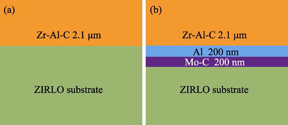
The monolithic Zr-Al-C coating and the Al/Mo-C interlayer system were deposited on ZIRLO substrates at room temperature, by using magnetron sputtering system (KYZK Development Co, Ltd, China), and the design of the layered stacks was shown in Fig. 1. The nominal composition (wt%) of ZIRLO substrate is given as follows, Zr bal; Nb, 1.10; Sn, 1.10; O, 0.13; Fe, 0.11. The substrates were ultrasonically cleaned for 10 min in acetone then ethanol, and were blown dry in N2. The vacuum chamber was evacuated to a base pressure of approximate 0.1 mPa. The DC magnetron power was set at 150, 42, 450, and 50 W for four targets of Zr2Al, Al, graphite, and Mo, respectively. Prior to deposition, the targets were pre-sputtered for at least 15 min. During the deposition process, the working pressure of Ar was maintained at 0.5 Pa, with the substrate DC bias of -15 V. A shutter was installed between the target and the substrate holder to allow the deposition of one element. After deposition, the samples were isothermally annealed at 800 ℃ for 3 h in the vacuum below 2 mPa. The heating and cooling rates were both set at 5 K/min.
![]()
Figure 1.Schematic views of the monolithic Zr-Al-C coating and the Al/Mo-C interlayer system
X-ray diffractometry (XRD) for phase identification was performed by a Bruker D8 Advance diffractometer with a Cu Kα radiation at a step of θ=0.02°. Surface and cross-section microstructures were examined by a field emission scanning electron microscope (SEM, FEI Quanta FEG 250). The compositional profiles of the coatings were determined by energy dispersive X-Ray spectroscopy (EDX, Oxford instruments X-MAX 50), with an accelerating voltage of 20 kV. Transmission electron microscope (TEM) characterization was performed in an FEI Tecnai F20 microscope operated at an acceleration voltage of 200 kV. The cross-sectional TEM samples were prepared by focused ion beam (FIB) microscope (Auriga, Carl Zeiss). Firstly, a target area of 5 μm ×7 μm was selected on the surface of the sample, and a layer of Pt (1-2 μm) is deposited on the target area to protect the sample. Then the rectangular region was bombarded to a depth of 5 μm by the Ga ion beams. The sides of the samples were thinned to 500 nm at the voltage of 30 kV and the current of 6-3 nA, and was further thinned to 100 nm when the voltage and current were reduced to 5 kV and 130 pA, respectively. Scratch tests were performed using a CSM Revetest scratch tester (CSM Instruments, Switzerland) with a Rockwell C diamond indenter with a tip radius of 200 μm. The indenter was moved at the speed of 0.05 mm/s, and the linear loading rate was 1-50 N in 60 s.
2 Results and discussion
2.1 Zr-Al-C coatings without interlayer on ZIRLO substrates
The average atomic ratio of the deposited Zr-Al-C coatings is as follows: Zr 30.3%, Al 46.3%, C 23.4%. The results indicate that the composition of the films is close to the ideal stoichiometry of Zr:Al (2:3) in the Zr2Al3C4 phase. SEM images of the surface and cross- section of the Zr-Al-C coatings on Zr-alloy substrate (as-deposited and annealed at 800 ℃) are shown in Fig. 2. It can be seen that the as-deposited coating is uniform and dense, but exhibit some small holes. The thickness of the coating is approximately 2.1 μm and the growth of the coating is columnar.
![]()
Figure 2.SEM images of the monolithic Zr-Al-C coating on ZIRLO substrate(a-b) Surface top view and cross section view of as-deposited coating; (c-d) Surface top view and cross section view of the coating annealed at 800 ℃ and its EDS line-scan
However, after annealing at 800 ℃ for 3 h, the coating shows a completely different morphology, being granular, and exhibiting other defects. As shown in Fig. 2(c), the coating shows a number of cracks; cracks are also observed for coatings annealed at other temperatures. The CTE mismatch between the substrate and the coating will induce cracking of the coating after annealing at high temperature. The cross-section SEM image in Fig. 2(d) shows that a reaction zone is formed between the coating and the substrate. The EDS line-scan also indicated that Al diffused into substrate and some Zr diffused into the coating. The Al and Zr compositions of the annealed coating by EDS are as follows: Al 16.8%, Zr 34.3%. The Al/Zr ration decreases to 0.49 after annealing. It can therefore be concluded that it is necessary for an interlayer both to improve the thermal expansion mismatch and consequently adhesion, and to prevent interdiffusion. Fig. 3 shows XRD patterns of the as- deposited and annealed coatings on the ZIRLO substrates without any interlayer.
![]()
Figure 3.XRD patterns of the as-deposited and annealed coatings on ZIRLO substrates without any interlayer
2.2 Zr-Al-C coatings with Al/Mo-C interlayer on ZIRLO substrates
Fig. 4 shows the SEM images of the surface and cross section of the 800 ℃-annealed coatings on ZIRLO substrates. In Fig. 4(a), the annealed coating is smooth, dense, uniform, and free of cracks, holes or other defects at this length scale. The as-synthesized Zr2Al3C4 coating has an anisotropic microstructure of lath-like interlaced growth (Fig. 4(b)), which is consistent with the structure of the bulk Zr2Al3C4 reported in the literature[
![]()
Figure 4.SEM images of the multilayered C-Mo/Al/Zr-Al-C annealed coatings on ZIRLO substrate and EDS line scan along the cross-section(a-b) Surface top view; (c) Cross section view; (d) EDS-line scan of the coating along the cross-section line in (c) from top and bottom
The XRD patterns of the as-deposited and annealed coatings with Al/Mo-C interlayer are shown in Fig. 5. The as-deposited multilayer coating exhibits similar diffraction peaks to the monolithic coating, but the annealed coating is completely different. The typical diffraction peak at 2θ=7.9° was detected in the XRD pattern, which can be assigned to diffraction from the basal planes (002) of the Zr2Al3C4 phase. Furthermore, the seven peaks at 2θ=22.9°, 33.2°, 36.8°, 40.5°, 45.3°, 51.7°, 55.5° and 66.5° belonged to the Zr2Al3C4 phase (PDF# 78-1801). After annealing at 800 ˚C for 3 h, the Zr2Al3C4 phase formed in the coating with the C-Mo/Al interlayer, as demonstrated in the XRD pattern of the annealed coating. Besides the Zr2Al3C4 phase, the ZrAl3 and the Zr3Al3C5 phases were also detected in the annealed coating. In the synthesis of Zr2Al3C4 bulk, it was found that Zr2Al3C4 balanced with ZrC, Zr3Al3C5, and Zr-Al intermetallics[
![]()
Figure 5.XRD patterns of as-deposited and annealed coatings on ZIRLO substrates with Al/Mo-C interlayer
In order to get more information about the microstructures of the coatings before and after annealing, the as-deposited and annealed multilayer coatings were characterized by TEM. The cross-section bright field TEM images of as-deposited C-Mo/Al/Zr-Al-C multilayer coatings on ZIRLO substrates are shown in Fig. 6(a-c). In the low magnification image (Fig. 6(a)), a detail of this multilayer structure is clearly observed: it is clearly visible that the Zr-Al-C, and -Al with C-Mo as the initial layer deposited on the substrate are stacked in sequence. Fig. 6(b-c) show the selected-area electron diffraction pattern (SADE) and bright-field TEM image of the Zr-Al-C layer. The presence of the single halo ring indicates that the deposited layer has a typical amorphous structure. Fig. 6(d-f) show the cross-sectional TEM images of the composite coating annealed at 800 ℃. As shown in Fig. 6(d), the interface of the interlayer can still be clearly observed after annealing. In Fig. 6(e), the selected area diffraction from the Zr-Al-C layer region consists of several diffractions and spots, indicating that the grain orientation is random. In a high-resolution TEM image (Fig. 6(f)), the typical nanolaminated microstructure similar to the traditional MAX phase is shown. The layered pattern has a vertical period of 2.22 nm, which matches with the c lattice parameter of Zr2Al3C4[
![]()
Figure 6.TEM cross-section images and digital image of C-Mo/Al/Zr-Al-C multilayer coatings on ZIRLO substrates(a, d) Overview images; (b, e) Selective area electron diffraction (SAED) patterns marked in (a) and (d), respectively; (c, f) HRTEM images
2.3 Coating-substrate adhesion
Fig. 7(a) shows the images of the whole scratch track of the Zr-Al-C annealed coating without interlayer and its acoustic emission (AE) siginal as the function of load. It is also obvious from the optical micrograph that there are a large number of vertical and horizontal cracks on the surface of the coating. When the load initially increases from 0 N, the corresponding AE signal shows large fluctuations, indicating strong effects between the coating and the substrate. The coating begins to peel off partially from the substrate as the load increases, and the substrate is completely exposed at a normal load of ~ 9 N. In contrast, according to the scratch test, the adhesion of the multilayer coating substrate system is stronger than that of the monolithic layer. An image of the whole scratch track of the Zr-Al-C coating with C-Mo/Al interlayer and its AE signal as the function of load, are shown in Fig. 7(b). Besides some local delamination and fragment, the multilayer coating retained strong adhesion on the Zr substrate when the normal load varies from 0 to 30 N. The coating began to locally peel from the substrate at the normal load of 30 N, so the adhesion of the multilayer coating-substrate can be increased to 30 N. The thermal stress generated during heating could be effectively alleviated by the Al/Mo-C interlayer. In Fig. 4(c-d), mixed C, Mo and Zr could be observed in the diffusion zone of approximately 200 nm. The diffusion zone could also increase the adhesion of the coating.
![]()
Figure 7.Optical micrographs of scratch tracks and acoustic emission signals as functions of load for the annealed coatings on the Zr-substrate(a) Zr-Al-C coating without interlayer; (b) Coating with Al/Mo-C interlayer
3 Conclusions
In summary, Zr2Al3C4 phase was synthesized on ZIRLO substrates using magnetron-sputter-deposited Zr-Al-C coatings with Al/Mo-C interlayer post-annealed at 800 ℃ for 3 h. The interdiffusion between the Zr-Al-C coating and the ZIRLO substrate during annealing could be impeded by Al/Mo-C interlayer, which is helpful to form Zr2Al3C4. At the same time, Al/Mo-C interlayer could alleviate the thermal stress of Zr-Al-C coating and the zirconium alloy substrate during the annealing to obtain a crack-free coating. Finally, the scratch test further confirmed that adhesion of the annealed Zr-Al-C coating- substrate was improved by the Al/Mo-C interlayer.
References
[1] H G KIM, J H YANG, W J KIM et al. Development status of accident-tolerant fuel for light water reactors in Korea. Nuclear Engineering & Technology, 48, 1-15(2016).
[2] D J PARK, H G KIM, Y I JUNG et al. Behavior of an improved Zr fuel cladding with oxidation resistant coating under loss-of-coolant accident conditions. Journal of Nuclear Materials, 482, 75-82(2016).
[3] C M LEE, D S SOHN. Enhanced high-temperature oxidation resistance of a zircon-nium alloy cladding by high-temperature preformed oxide on the cladding. Corrosion Science, 131, 116-125(2018).
[4] M KURATA. Research and development methodology for practical use of accident tolerant fuel in light water reactors. Nuclear Engineering & Technology, 48, 26-32(2016).
[5] M W BARSOUM. The M
[6] Z M SUN. Progress in research and development on MAX phase: a family of layered ternary compounds. International Materials Reviews, 56, 143-166(2011).
[7] C C LAI, M D TUCKER, P EKLUND et al. Synthesis and characterization of Zr2Al3C4 thin films. Thin Solid Films, 595, 142-147(2015).
[8] E N HOFFMAN, D W VINSON, P L SINDELAR et al. MAX phase carbides and nitrides: properties for future nuclearpower plant in-core applications and neutron transmutation analysis. Nuclear Engineering and Design, 244, 17-24(2012).
[10] T LAPAUW, K LAMBRINOU, T CABIOC’H et al. Synthesis of the new MAX phase Zr2AlC. Journal of the European Ceramic Society, 36, 1847-1853(2016).
[11] T LAPAUW, J HALIM, J LU et al. Synthesis of the novel Zr3AlC2 MAX phase. Journal of the European Ceramic Society, 36, 943-947(2016).
[12] H H QARRA, K M KNOWLES, M E VICKERS et al. Heavy ion irradiation damage in Zr3(Al0.9Si0.1)C MAX phase. Journal of Nuclear Materials, 540(2020).
[13] Y C ZHOU, L F HE, Z J LIN et al. Synthesis and structure- property relationships of a new family of layered carbides in Zr-Al(Si)-C and Hf-Al(Si)-C systems. Journal of the European Ceramic Society, 33, 2831-2865(2013).
[14] L F HE, Z J LIN, J Y WANG et al. Synthesis and characterization of bulk Zr2Al3C4 ceramic. Journal of the American Ceramic Society, 90, 3687-3689(2007).
[15] K FUKUDA, S MORI, S HASHIMOTO. Crystal structure of Zr2Al3C4. Journal of the American Ceramic Society, 88, 3528-3530(2005).
[16] L F HE, X P LU, Y W BAO et al. High-temperature internal friction, stiffness and strength of Zr-Al(Si)-C ceramics. Scripta Materialia, 61, 60-63(2009).
[17] L F HE, H B ZHONG, J J XU et al. Ultrahigh temperature oxidation of Zr2Al3C4
[18] V PETUKHOV. Thermal expansion of zirconium in the solid phase. High Temperatures High Pressures, 35-36, 15-23(2003).
[19] J M Liang, Q Wei, F F Ge et al. Synthesis of Zr2Al3C4 coatings on zirconium-alloy substrates with Al-C/Si interlayers as diffusion barriers. Vacuum, 160, 128-132(2018).


Set citation alerts for the article
Please enter your email address

© Copyright 2018-2021 | Chinese Laser Press. All Rights Reserved 沪ICP备15018463号-20