
Ningning Dong, Qianghu Liu, Jun Wang. Research Progress of Two-Dimensional Nonlinear Optical Limiting Materials[J]. Chinese Journal of Lasers, 2021, 48(13): 1300001
- Chinese Journal of Lasers
- Vol. 48, Issue 13, 1300001 (2021)
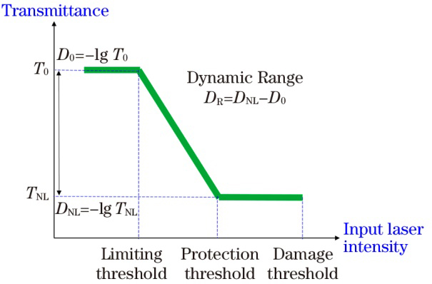
Fig. 1. Principle diagram of ideal optical limiter
![Research status of optical limiting[4]](/richHtml/zgjg/2021/48/13/1300001/img_2.jpg)
Fig. 2. Research status of optical limiting[4]
Fig. 3. Optical limiting properties of graphene. (a)(b) Nonlinear transmittance and scattering signal of graphene dispersions versus incident laser energy density[22]; (c)(d) open aperture Z-scan curves of graphene NMP dispersions under action of nanosecond pulse laser [23]; high-magnification (e) SEM and (f) TEM images of etched graphene[24]; (g) open aperture Z-scan curves of different materials[24]; (h) normalized transmittance versus incident laser fluence [24]
Fig. 4. Optical limiting properties of different nanostructured graphene dispersions under action of 532 nm and 1064 nm nanosecond lasers[25]. (a)(b) Normalized transmittance; (c)(d) scattering signals
Fig. 5. Nonlinear optical properties and mechanisms of MoX2 dispersions. (a)(b) open aperture Z-scan results of MoX2 dispersions under action of femtosecond laser[33] ; (c)(d) normalized transmittance (solid circles) and scattering signals (open circles) of TMDCs suspensions[34]; (e) mechanism diagram of all-optical modulation[35]; (f) mechanism diagram of SA and NLS of nanosheet dispersions[35]
Fig. 6. Nonlinear optical properties of TMDCs. (a) Two-photon absorption property of monolayer MoS2 under action of near-infrared femtosecond laser[36]; (b) SA property of multilayer MoS2[36] ; (c) two-photon absorption coefficients of cm-scaled few-layered WS2 under 1030 nm laser irradiation[37]; (d) four two-photon absorption saturation models[38]; (e)(f) self-focusing and defocusing behaviors of monolayer and bulk WS2 [39]
Fig. 7. Optical limiting properties of MoS2 composite materials under 532 nm and 1064 nm laser irradiation. (a)(b) Output fluence versus input fluence for MoS2/PMMA composite materials [40]; (c)(d) normalized transmittance versus input laser intensity for MoS2 composite materials[41]
Fig. 8. Nonlinear optical properties of BP nanosheets. (a)--(c) Z scan results under action of 1064, 532, 355 nm lasers[48]; (d) normalized transmittance versus input laser intensity for each wavelength[48]; (e) optical modulation properties of BP dispersions[49]; (f) modulation depths under different pump fluences[49]; (g) open aperture Z-scan results and corresponding (h) scattering signals[49]
|
Table 1. Summarization of several laser protection technologies


Set citation alerts for the article
Please enter your email address

© Copyright 2018-2021 | Chinese Laser Press. All Rights Reserved 沪ICP备15018463号-20