
Qi Wu, Yixiao Zhu, Ziyu Cheng, Longjie Yin, Weisheng Hu. Spectrally sliced heterodyne coherent receiver with halved electrical bandwidth[J]. Chinese Optics Letters, 2022, 20(9): 090601
- Chinese Optics Letters
- Vol. 20, Issue 9, 090601 (2022)
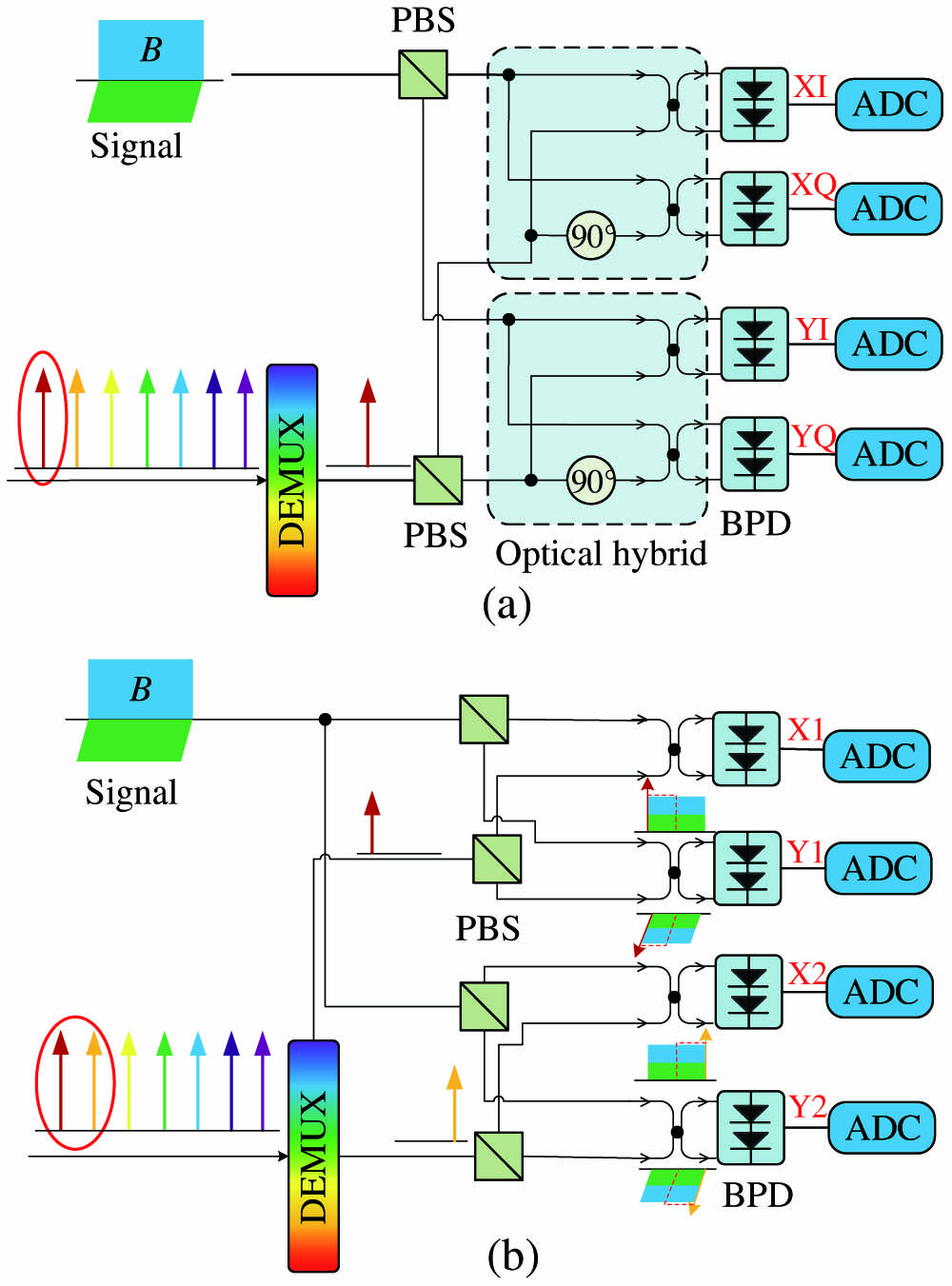
Fig. 1. Configuration of (a) the ICR and (b) the proposed SHCR in OFC-based architecture. ADC, analog-to-digital converter; DEMUX, demultiplexer; PBS, polarization beam splitter.
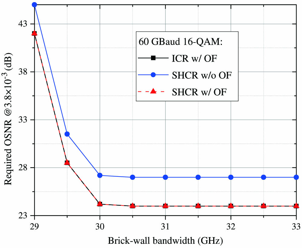
Fig. 2. Simulated OSNR sensitivity as a function of brick-wall electrical bandwidth in ICR and SHCR. OF, optical filter.
Fig. 3. Simulated OSNR sensitivity as a function of the different linewidths of the laser in ICR and SHCR. OF, optical filter.
Fig. 4. Experimental setup of the SHCR. ECL, external cavity laser; AWG, arbitrary waveform generator; IQ Mod., IQ modulator; EA, electrical amplifier; EDFA, erbium-doped fiber amplifier; BPD, balanced photodetector; MZM, Mach–Zehnder modulator; OBPF, optical band-pass filter; PC, polarization controller; RF, radio frequency; DSO, digital storage oscilloscope.
Fig. 5. (a) DSP stack at the transmitter. (b) DSP stack at the receiver. RRC, root raised cosine; FOE, frequency offset estimation; CPE, carrier phase recovery; DD-LMS, decision-directed least minimum square; PF, post filter; MLSE, maximum likelihood sequence estimation.
Fig. 6. Optical spectra of the signal at stages (i), (ii), and (iii) of Fig. 4 .
Fig. 7. Electrical spectra of the left- and right-side signal after (a) resampling, (b) FOE, and (c) MIMO equalization.
Fig. 8. Measured BER as a function of channel skew for 60-GBaud 16-QAM signal with the different number of equalizer taps.
Fig. 9. Measured BER as a function of the brick-wall electrical bandwidth of the receiver for the 60 GBaud 16-QAM signal in the BTB case and 80 km SSMF transmission case.
Fig. 10. Measured BER versus ROP for the 60 GBaud 16-QAM signal at the BTB and 80 km SSMF transmission cases.

Set citation alerts for the article
Please enter your email address
© Copyright 2018-2021 | Chinese Laser Press. All Rights Reserved 沪ICP备15018463号-20