
Qi Wu, Yixiao Zhu, Ziyu Cheng, Longjie Yin, Weisheng Hu. Spectrally sliced heterodyne coherent receiver with halved electrical bandwidth[J]. Chinese Optics Letters, 2022, 20(9): 090601
- Chinese Optics Letters
- Vol. 20, Issue 9, 090601 (2022)
Abstract
1. Introduction
Since 2005, digital coherent receivers have brought optical communication into a new era[
To simplify the structure of a standard ICR, one attempt is to replace balanced photodetectors (BPDs) with single-ended photodetectors (SPDs)[
In comparison, the HCR can reduce the hardware complexity to two BPDs and two ADCs[
Sign up for Chinese Optics Letters TOC. Get the latest issue of Chinese Optics Letters delivered right to you!Sign up now
In the scenario of data center interconnection (DCI), 4/8-lane coarse-WDM (CWDM)-based IMDD systems have been widely adopted[
In this work, we propose a spectrally sliced HCR (SHCR) to relax electrical requirements for ADCs and PDs of a heterodyne coherent detection system for intra-DCI interconnects and the scenarios with the OFC as a laser source. The proposed SHCR utilizes the two comb lines to halve the required electrical bandwidth in the HCR. Thanks to spectrally sliced detection, the required electrical bandwidth for SHCR is reduced by almost half compared with the conventional HCR. Assisted with OFC and advanced digital processing techniques, the proposed SHCR fully utilizes the electrical bandwidth of the receiver, slightly reducing the hardware cost of coherent detection since it eliminates the utilization of optical hybrids, and the cost induced by OFC is shared equally in all WDM channels.
2. Principle of SHCR and Simulations
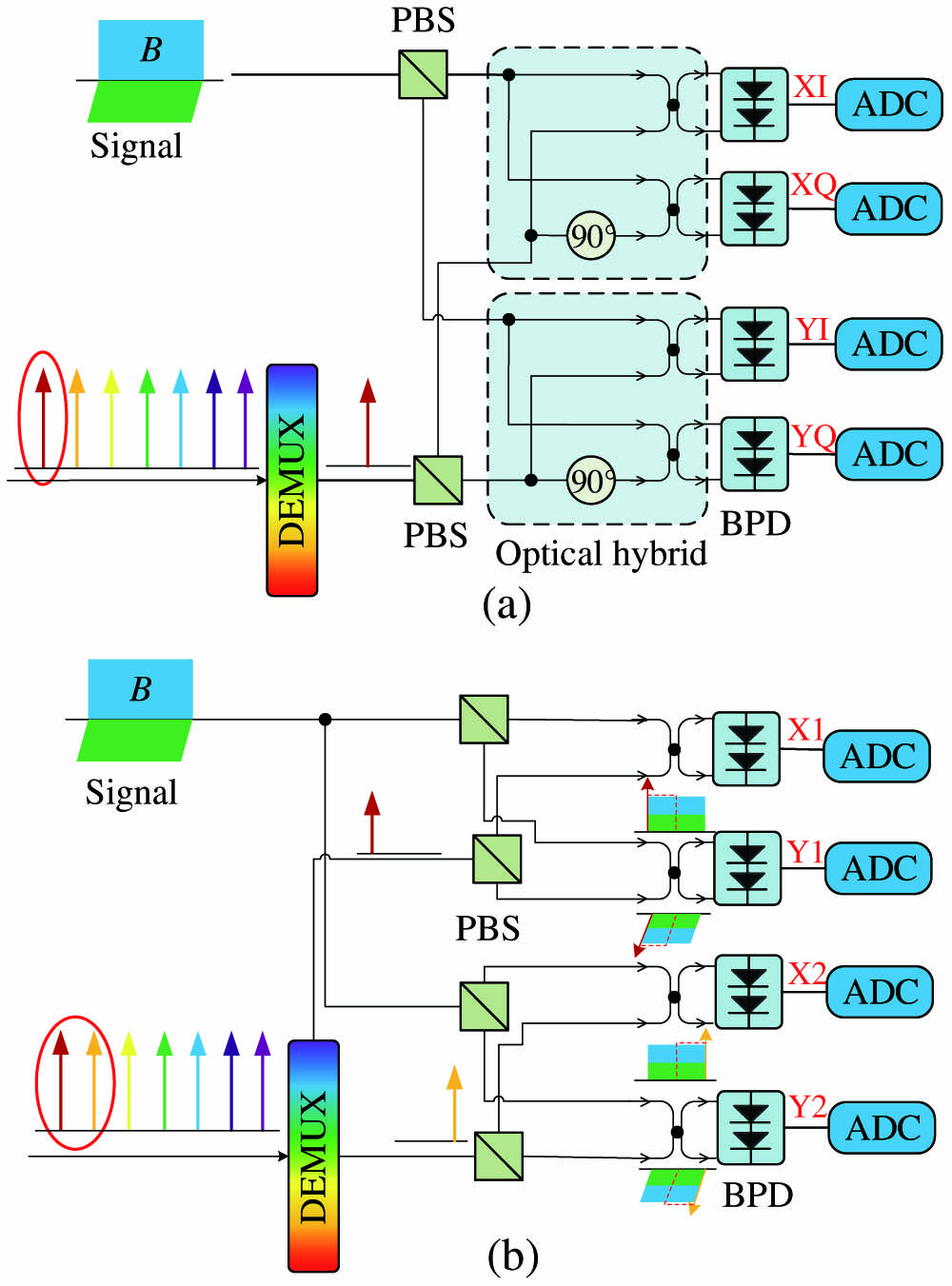
The ICR and proposed SHCR are depicted in Figs. 1(a) and 1(b). Figure 1(a) shows the configuration of a standard ICR. As we can see, it requires four BPDs and two optical hybrids to obtain the I/Q information of signals. The comb line demultiplexed from an OFC serves as an LO. The IQ components of the received optical signal with polarization diversity are linearly mapped to the electrical domain by mixing the received optical field with an LO. This direct mapping enables impairments compensation in the receiver DSP, which then allows the use of high-order quadrature amplitude modulation (QAM) formats.
![]()
Figure 1.Configuration of (a) the ICR and (b) the proposed SHCR in OFC-based architecture. ADC, analog-to-digital converter; DEMUX, demultiplexer; PBS, polarization beam splitter.
The baseband signal is directly obtained for intradyne detection, so its predominant advantage is the halved electrical bandwidth, compared with traditional heterodyne detection, which requires a relatively high intermediate frequency (IF) that should be higher than the signal bandwidth. For instance, assuming that the bandwidth of a signal is , the ICR only requires the electrical bandwidth of to recover the signal, while the traditional HCR requires the electrical bandwidth of , which contributes to all the field-deployed coherent receivers being intradyne configurations.
The configuration of the proposed SHCR is shown in Fig. 1(b), where two comb lines with the same phase characteristics are demultiplexed through a wave-shaper or inter-leaver to serve as two LOs with different frequencies. After mixing two comb lines with optical signals in couplers, respectively, the optical fields are square-law detected by four BPDs. The four channels from top to bottom in our proposed receiver are labeled as X1, Y1, X2, Y2, respectively. It is worth noting that we use four ADCs with only half of the signal bandwidth () to capture the waveforms, leading to a doubled electrical spectral efficiency in contrast to HCR. Only half of the spectrum information of the signal is received in each channel since the bandwidth of the ADC is . Nevertheless, the signal spectrum in both polarizations has been completely captured thanks to the frequency spacing between two LOs. Compared with ICR, the 90° optical hybrids can be eliminated in the SHCR at the cost of two polarization beam splitters (PBSs) and five optical couplers.
In theory[
To numerically verify the principle and feasibility of the proposed SHCR, we conduct simulations using commercial software VPItransmissionMaker. The 60 GBaud 16-QAM Nyquist pulse with a 0.01 roll-off factor is generated, leading to 60.6 () GHz bandwidth of the electrical signal.
We simulated the optical signal-to-noise ratio (OSNR) sensitivity as a function of the ADC bandwidth with a bit-error-rate (BER) below 7% hard-decision forward error correction (HD-FEC) of , which is shown in Fig. 2. The LO power is defined as the power of a single comb line before photoelectric conversion. The LO power is set as 16 dBm to suppress SSBI, and PD noise is loaded into the signal including thermal noise, dark current, and shot noise. It can be observed that there is a 3 dB OSNR gap between ICR and HCR without an optical filter because the heterodyne detection suffers from the optical noise folding impact. Fortunately, the optical filter exists in the intra-DCI. Therefore, the 3 dB OSNR induced by optical noise folding can be removed. The OSNR sensitivity of both ICR and SHCR degrade rapidly when electrical bandwidth is below the Nyquist bandwidth of 30.3 GHz in our cases. Therefore, the penalties resulting from electrical bandwidth are the same for both schemes.
![]()
Figure 2.Simulated OSNR sensitivity as a function of brick-wall electrical bandwidth in ICR and SHCR. OF, optical filter.
Figure 3 depicts the OSNR sensitivity as a function of linewidth from 1 kHz to 1 MHz in the ICR and SHCR schemes. The linewidth increase from 100 kHz to 1 MHz does a large amount of damage to both receivers. The deterioration trend in OSNR sensitivity of the two receivers is the same, which indicates that SHCR also needs a narrow linewidth laser for coherent detection, and the phase noise imposes no extra penalty on the MIMO performance in SHCR.
![]()
Figure 3.Simulated OSNR sensitivity as a function of the different linewidths of the laser in ICR and SHCR. OF, optical filter.
3. Experimental Setup and DSP Procedures
We experimentally validate the principle of SHCR. As a proof-of-concept experiment, we demonstrate a single-polarization experiment here to illustrate the feasibility of the proposed SHCR scheme due to the lack of BPDs and a four-channel digital storage oscilloscope (DSO). The experimental setup of the proposed SHCR is depicted in Fig. 4. The DSP stacks of the transmitter and receiver are shown in Figs. 5(a) and 5(b), respectively. An external cavity laser (ECL) with linewidth is employed as the light source at the transmitter. An arbitrary waveform generator (Keysight M8194) with a 45 GHz electrical bandwidth operating at 120 GSa/s generates a 60 GBaud 16-QAM Nyquist pulse with a roll-off factor of 0.01. After being amplified by a dual-channel electrical amplifier (OA4SMM4), the IQ components of the complex-valued signal are loaded into an IQ modulator of 25 GHz 3 dB bandwidth biased at the null point to modulate the light from ECL1 (at 1542.14 nm). Then, the optical signal is amplified by an erbium-doped fiber amplifier (EDFA) and launched to an 80 km standard single-mode fiber (SSMF) with a launch power of 3 dBm.
![]()
Figure 4.Experimental setup of the SHCR. ECL, external cavity laser; AWG, arbitrary waveform generator; IQ Mod., IQ modulator; EA, electrical amplifier; EDFA, erbium-doped fiber amplifier; BPD, balanced photodetector; MZM, Mach–Zehnder modulator; OBPF, optical band-pass filter; PC, polarization controller; RF, radio frequency; DSO, digital storage oscilloscope.
![]()
Figure 5.(a) DSP stack at the transmitter. (b) DSP stack at the receiver. RRC, root raised cosine; FOE, frequency offset estimation; CPE, carrier phase recovery; DD-LMS, decision-directed least minimum square; PF, post filter; MLSE, maximum likelihood sequence estimation.
At the receiver, the optical signal is amplified, filtered using an optical band-pass filter (OBPF), and then divided into two by a coupler. The optical spectrum of the signal at stage (i) of Fig. 4 is shown in Fig. 6. The 31 GHz sinusoidal wave from the radio-frequency source (MXG N5183A) is fed into a Mach–Zehnder modulator (MZM) for two-tone LO generation at 1541.90 nm and 1542.39 nm. Then, the two comb lines are amplified by two EDFAs and filtered out by two OBPFs, respectively. Finally, the two LOs with a frequency gap of 62 GHz and 11 dBm power are obtained. We use polarization controllers to realize the polarization alignment of the signal and the two LOs, and then the two LOs are coupled together with two signal copies by two optical couplers. The optical spectra at stage (ii) and stage (iii) of Fig. 4 are depicted in Fig. 6. Then, optical waveforms in these two channels are detected by two 43 GHz BPDs (FINISAR BPDV21x0R), and the photocurrents, labeled as X1 and X2, are captured by a real-time DSO with a 33 GHz brick-wall electrical bandwidth (Tektronix DPO75902SX) operating at 100 GSa/s for offline DSP.
![]()
Figure 6.Optical spectra of the signal at stages (i), (ii), and (iii) of Fig.
The electrical spectra after resampling, FOE, and MIMO equalization are displayed in Figs. 7(a)–7(c), respectively. The black electrical spectrum is from channel X1, corresponding to the black optical spectrum in Fig. 6, and the blue electrical spectrum corresponds to channel X2. At the receiver DSP, the two detected waveforms from X1 and X2 are firstly resampled to two sample-per-symbols (SPS). Then, the frequency offset between the transmitter laser and the two-tone LO is estimated based on the residual carrier generated by the drift of the IQ modulator bias point, which is circled in Fig. 7(a). FOE based on the residual carrier could further reduce the computational complexity of DSP. After CD compensation and matched filter, the two signals are fed into an MIMO equalizer operating at two SPS for ISI cancellation. As shown in Fig. 7(b), the electrical spectra after FOE only contain the left or right side of the signal spectrum information. However, thanks to the MIMO equalization, the complete spectrum is obtained by combining the left-side part from X1 and the right side from X2, as shown in Fig. 7(c). The taps of the MIMO equalizer are updated by the recursive least square (RLS) algorithm based on training sequences. After equalization, the carrier phase recovery based on the inserted pilot symbols and blind phase search[
![]()
Figure 7.Electrical spectra of the left- and right-side signal after (a) resampling, (b) FOE, and (c) MIMO equalization.
4. Results and Discussion
The proposed SHCR has a skew between channels X1 and X2 from implementation, similar to the IQ skew in the ICR[
![]()
Figure 8.Measured BER as a function of channel skew for 60-GBaud 16-QAM signal with the different number of equalizer taps.
The MIMO equalizer operates at two SPS, so the thresholds for the 20/30/40 taps equalizer are 166.67 ps, 250 ps, and 333.33 ps, respectively. Therefore, more filter taps indicate higher skew tolerance but also higher computational complexity. In the following context, we fix the number of taps as 30 to investigate bandwidth tolerance and the received optical power (ROP) of SHCR.
Then, we investigate the electrical bandwidth tolerance of SHCR. Figure 9 shows the BERs versus different brick-wall electrical bandwidths for a 60 GBaud 16-QAM at the BTB and 80 km SSMF transmission. As seen in Fig. 9, the BER performance deteriorates slowly with the electrical bandwidth decreasing from 33 GHz to 31 GHz since the frequency gap between two LOs is 62 GHz. The 31 GHz electrical bandwidth is sufficient for the ADCs and BPDs in the SHCR to obtain complete spectrum information to recover the original signal. As the electrical bandwidth further decreases, part of the spectrum information is lost, which causes severe damage to signal recovery. The results in our experiments are highly consistent with the above simulation.
![]()
Figure 9.Measured BER as a function of the brick-wall electrical bandwidth of the receiver for the 60 GBaud 16-QAM signal in the BTB case and 80 km SSMF transmission case.
The measured BER versus ROP at BTB and 80 km SSMF transmission scenarios is displayed in Fig. 10. The optimal performance of the receiver is obtained at ROP. The corresponding BER is below the 7% HD-FEC threshold of . After 80 km SSMF transmission, there is a 1.2 dB sensitivity penalty at the BER threshold of 7% HD-FEC, part of which is caused by the amplified spontaneous emission noise of the EDFA. Note that the performance could be further improved by applying transimpedance amplifiers after the photodiodes.
![]()
Figure 10.Measured BER versus ROP for the 60 GBaud 16-QAM signal at the BTB and 80 km SSMF transmission cases.
The computational complexity of the DSP procedures used in the proposed SHCR is analyzed as follows. The residual carrier-assisted FOE only relies on Fourier transform and peak searching and exhibits lower complexity than the fourth power algorithm[
5. Conclusion
In this work, we propose a spectrally sliced coherent detection scheme called SHCR to improve the tolerance to electrical bandwidth in the heterodyne coherent detection. The key idea of the proposed SHCR is to employ spectrally sliced detection and MIMO equalization to complete full spectrum recovery. The performance of the SHCR scheme is numerically compared with ICR. A 60 GBaud Nyquist 16-QAM transmission over 80 km SSMF is experimentally demonstrated to validate its principle and feasibility. The SHCR shows good tolerance to laser linewidth, fiber dispersion, channel skew, and electrical bandwidth based on the numerical and experimental results. This is the first, to the best of our knowledge, realization of heterodyne detection with a low receiver bandwidth at almost half of the baud rate.
References
[1] S. Tsukamoto, D. Ly-Gagnon, K. Katoh, K. Kikuchi. Coherent demodulation of 40-Gbit/s polarization-multiplexed QPSK signals with 16-GHz spacing after 200-km transmission. Optical Fiber Communication Conference, PDP29(2005).
[2] K. Kikuchi. Fundamentals of coherent optical fiber communications. J. Light. Technol., 34, 157(2016).
[3] K. Kikuchi, S. Tsukamoto. Evaluation of sensitivity of the digital coherent receiver. J. Light. Technol., 26, 1817(2008).
[4] S. Lu, Y. Zhou, F. Zhu, J. Sun, Y. Yang, R. Zhu, S. Hu, X. Zhang, X. Zhu, X. Hou, W. Chen. Digital-analog hybrid optical phase-lock loop for optical quadrature phase-shift keying. Chin. Opt. Lett., 18, 090602(2020).
[5] S. J. Savory. Digital filters for coherent optical receivers. Opt. Express, 16, 804(2008).
[6] X. Zhou, J. Yu, D. Qian. A novel DSP algorithm for improving the performance of digital coherent receiver using single-ended photo detection. European Conference on Optical Communication, Mo4D.1(2008).
[7] S. T. Le, V. Aref, J. Cho, X. Chen, D. Che. 882 Gbps transmission over 100 km of SSMF using a self-calibrated single-ended coherent receiver. Optical Fiber Communication Conference, M3I.2(2021).
[8] C. Xie, P. J. Winzer, G. Raybon, A. H. Gnauck, B. Y. Zhu, T. Geisler, B. Edvold. Colorless coherent receiver using 3×3 coupler hybrids and single-ended detection. Opt. Express, 20, 1164(2012).
[9] J. Zhang, Z. Dong, J. Yu, N. Chi, L. Tao, X. Li, Y. Shao. Simplified coherent receiver with heterodyne detection of eight-channel 50 Gb/s PDM-QPSK WDM signal after 1040 km SMF-28 transmission. Opt. Lett., 37, 4050(2012).
[10] X. Li, J. Yu, N. Chi, Z. Dong, J. Zhang, J. Yu. The reduction of the LO number for heterodyne coherent detection. Opt. Express, 20, 29613(2012).
[11] W. Shieh, C. Sun, H. Ji. Carrier-assisted differential detection. Light Sci. Appl., 9, 18(2020).
[12] S. Kumar, G. Papen, K. Schmidtke, C. Xie. Intra-data center interconnects, networking, and architectures. Optical Fiber Telecommunications VII, 627(2020).
[13] H. Hu, L. K. Oxenløwe. Chip-based optical frequency combs for high-capacity optical communications. Nanophotonics, 10, 1367(2021).
[14] N. K. Fontaine, R. P. Scott, L. Zhou, F. M. Soares, J. P. Heritage, S. J. B. Yoo. Real-time full-field arbitrary optical waveform measurement. Nat. Photonics, 4, 248(2010).

Set citation alerts for the article
Please enter your email address
© Copyright 2018-2021 | Chinese Laser Press. All Rights Reserved 沪ICP备15018463号-20