Author Affiliations
1School of Physics and Electronic Engineering, Shanxi University, Taiyuan 030006, Shanxi , China2State Key Laboratory of Quantum Optics and Quantum Optics Devices, Institute of Laser-Spectroscopy, Shanxi University, Taiyuan 030006, Shanxi , China3Collaborative Innovation Center of Extreme Optics, College of Physics and Electronic Engineering, Shanxi University, Taiyuan 030006, Shanxi , Chinashow less
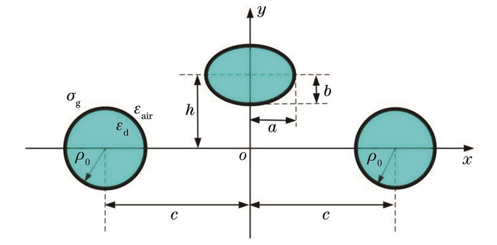
Fig. 1. Schematic diagram of cross-section of hybrid dielectric nanowire waveguide coated with graphene
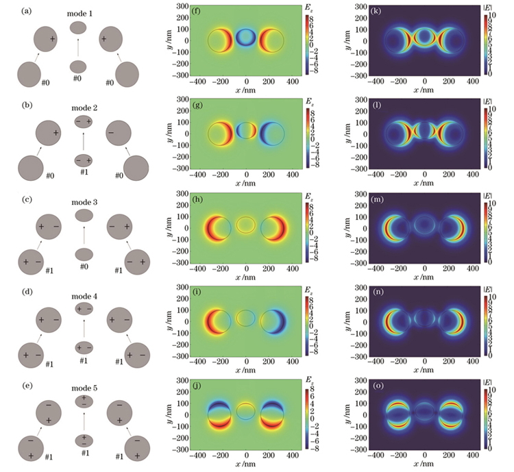
Fig. 2. Synthesis, electric field z component, and electric field intensity distributions of five lowest-order modes. (a)-(e) Synthesis of five lowest-order modes; (f)-(j) electric field z component; (k)-(o) electric field intensity distributions
Fig. 3. Rart part of effective refractive index , propagation length, and figure of merit FOM of five lowest-order modes varying with operating wavelength , and electric field intensity distributions at wavelengths of 6.2, 7.0, and 7.8 μm. (a) Real part of effective refractive index ; (b) propagation length; (c) figure of merit FOM; electric field intensity distributions at wavelengths of (d) , (e) , and (f)
Fig. 4. Real part of effective refractive index , propagation length ,and figure of merit FOM of five lowest-order modes varying with Fermi energy , and electric field intensity distributions at Fermi energies of 0.42, 0.50, and 0.58 eV. (a) Real part of effective refractive index ; (b) propagation length ; (c) figure of merit FOM; electric field intensity distributions at Fermi energies of (d) , (e) and (f)
Fig. 5. Real part of effective refractive index , propagation length , and figure of merit FOM of five lowest-order modes varying with radius 0, and electric field intensity distributions at radii 0 of . (a) Real part of effective refractive index ; (b) propagation length ; (c) figure of merit FOM; electric field intensity distributions at radii 0 of (d) , (e) , and (f)
Fig. 6. Real part of effective refractive index , propagation length ,and figure of merit FOM of five lowest-order modes varying with elliptic nanowire semi-major axis a,and electric field intensity distributions at elliptic nanowire semi-major axis of and . (a) Real part of effective refractive index ; (b) propagation length ; (c) figure of merit FOM; electric field intensity distributions at elliptic nanowire semi-major axis a of (d) , (e) , and (f)
Fig. 7. Real part of effective refractive index , propagation length ,and figure of merit FOM of five lowest-order modes varying with elliptical nanowire semi-minor axis b, and electric field intensity distributions at semi-minor axis of 70, and . (a) Real part of effective refractive index ; (b) propagation length ; (c) figure of merit FOM; electric field intensity distributions at semi-minor axis of (d) 62 nm, (e) 70 nm, and (f) 78 nm
Fig. 8. Real part of effective refractive index , propagation length ,and figure of merit FOM of five lowest-order modes varying with distance , and electric field intensity distributions at distances of 210, 230, and 250 nm. (a) Real part of effective refractive index ; (b) propagation length ; (c) figure of merit FOM; electric field intensity distributions at distances of (d) , (e) , and (f)
Fig. 9. Real part of effective refractive index , propagation length ,and figure of merit FOM of five lowest-order modes varying with height h, and electric field intensity distributions at heights of 0, 40, and 80 nm. (a) Real part of effective refractive index ; (b) propagation length ; (c) figure of merit FOM; electric field intensity distributions at heights of (d) , (e) , and (f)
Fig. 10. Comparison of real part of effective refractive index , propagation length ,and figure of merit of mode 1 supported by struct1 and struct2 varying with operating wavelength λ, and electric field intensity distributions of mode 1 supported by struct1 and struct2 at wavelength of . (a) Real part of effective refractive index ; (b) propagation length ; (c) figure of merit ; electric field intensity distributions of mode 1 supported by (d) struct1 and (e) struct2 at wavelength of
Fig. 11. Comparison of real part of effective refractive index ,propagation length,and figure of merit FOM of mode 1 supported by struct1 and struct2 varying with Fermi energy Ef, and electric field intensity distributions of mode 1 supported by struct1 and struct2 at Fermi energy of . (a) Real part of effective refractive index ; (b) propagation length ; (c) figure of merit FOM; electric field intensity distributions of mode 1 supported by (d) struct1 and (e) struct2 at Fermi energy of