• Matter and Radiation at Extremes
  • Vol. 4, Issue 2, 24402 (2019)
Deepak Kumar1、*, Michal ?míd1, Sushil Singh1, Alexander Soloviev2, Hannes Bohlin1, Konstantin Burdonov2, Gashaw Fente1, Alexander Kotov2, Livia Lancia3、4, Vit Lédl5, Sergey Makarov6, Michael Morrissey1, Sergey Perevalov2, Denis Romanovsky2, Sergey Pikuz6, Ryousuke Kodama7, David Neely8, Paul McKenna9, Tomá? La?tovi?ka1, Mikhail Starodubtsev2, Stefan Weber1, Motoaki Nakatsutsumi10, and Julien Fuchs3、4
Author Affiliations
  • 1ELI Beamlines, Institute of Physics, 5. května 835, 252 41 Dolní B?e?any, Czech Republic
  • 2Institute of Applied Physics of the Russian Academy of Sciences (IAP RAS), 46 Ul’yanov Street, 603950 Nizhny Novgorod, Russia
  • 3LULI—CNRS, Ecole Polytechnique, CEA: Université Paris-Saclay
  • 4UPMC Univ Paris 06: Sorbonne Universities, F-91128 Palaiseau Cedex, France
  • 5Research Center Toptec, Institute of Plasma Physics, Sobotecká 1660, 511 01 Turnov, Czech Republic
  • 6Joint Institute for High Temperatures Russian Academy of Science (JIHT RAS), Moscow 125412, Russia
  • 7Division of Electrical, Electronic and Information Engineering, Graduate School of Engineering, Osaka University, Osaka, Japan
  • 8Central Laser Facility, STFC Rutherford Appleton Laboratory, Didcot OX11 0QX, United Kingdom
  • 9Department of Physics SUPA, University of Strathclyde, Glasgow G4 0NG, United Kingdom
  • 10European XFEL GmbH, Holzkoppel 4, 22869 Schenefeld, Germany
  • show less
    DOI: 10.1063/1.5088166 Cite this Article
    Deepak Kumar, Michal ?míd, Sushil Singh, Alexander Soloviev, Hannes Bohlin, Konstantin Burdonov, Gashaw Fente, Alexander Kotov, Livia Lancia, Vit Lédl, Sergey Makarov, Michael Morrissey, Sergey Perevalov, Denis Romanovsky, Sergey Pikuz, Ryousuke Kodama, David Neely, Paul McKenna, Tomá? La?tovi?ka, Mikhail Starodubtsev, Stefan Weber, Motoaki Nakatsutsumi, Julien Fuchs. Alignment of solid targets under extreme tight focus conditions generated by an ellipsoidal plasma mirror[J]. Matter and Radiation at Extremes, 2019, 4(2): 24402 Copy Citation Text show less
    (a) Sectional view of the EPM, depicting the geometry. The boundary of the laser beam path is shown in red. Fin and Fout are the input and output foci, respectively, of the EPM. (b) Image of a machined EPM placed next to a 10 coin of diameter 17.5 mm. (c) Expected fluence in J/cm2 on the surface of the EPM when used with the PEARL laser delivering 20 J on target. All dimensions are in millimeters.
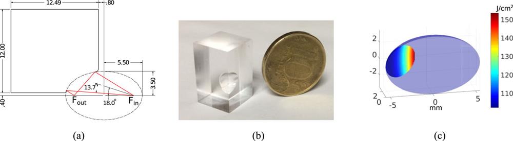
    Fig. 1. (a) Sectional view of the EPM, depicting the geometry. The boundary of the laser beam path is shown in red. Fin and Fout are the input and output foci, respectively, of the EPM. (b) Image of a machined EPM placed next to a 10 coin of diameter 17.5 mm. (c) Expected fluence in J/cm2 on the surface of the EPM when used with the PEARL laser delivering 20 J on target. All dimensions are in millimeters.
    Focal spot images normalized to peak intensity characterizing the performance of the EPMs. (a, b) Focal spot at the input (a) and output (b) of the EPM at the test bench. (c, d) Focal spots at the input (c) and (d) of the EPM at the PEARL laser facility as measured with low-power alignment beam. Field of view in all the images is 20 μm × 20 μm. The diameter of the full width at half maximum (FWHM) of the focal spot (ΦFWHM) and the fraction of energy enclosed within the FWHM (Eenc) are given in each image.
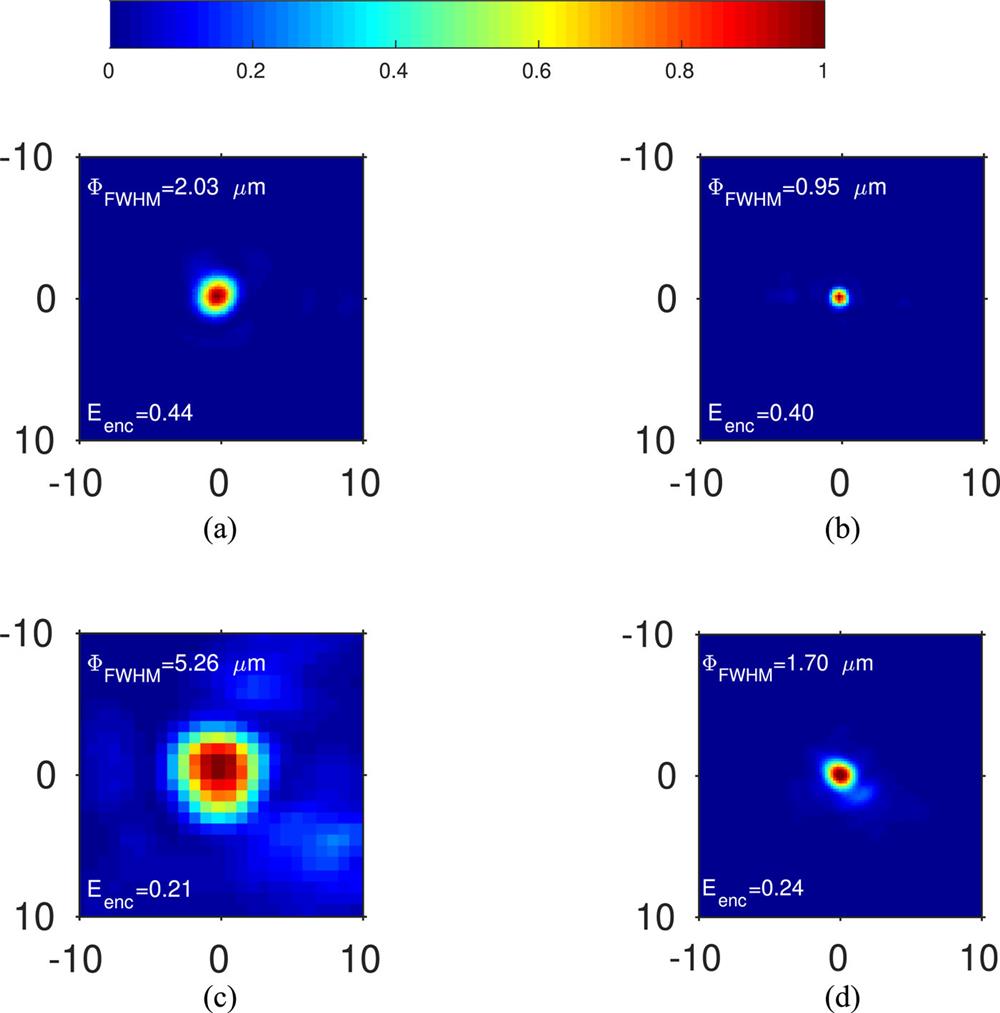
    Fig. 2. Focal spot images normalized to peak intensity characterizing the performance of the EPMs. (a, b) Focal spot at the input (a) and output (b) of the EPM at the test bench. (c, d) Focal spots at the input (c) and (d) of the EPM at the PEARL laser facility as measured with low-power alignment beam. Field of view in all the images is 20 μm × 20 μm. The diameter of the full width at half maximum (FWHM) of the focal spot (ΦFWHM) and the fraction of energy enclosed within the FWHM (Eenc) are given in each image.
    (a) Schematic of the setup used on the test bench to characterize the EPMs and benchmark the retro-alignment system. (b) Image of the setup, showing the physical layout of the components.
    Fig. 3. (a) Schematic of the setup used on the test bench to characterize the EPMs and benchmark the retro-alignment system. (b) Image of the setup, showing the physical layout of the components.
    Target alignment by monitoring the near field. (a) Schematic of the alignment method. (b) Near-field images during target alignment at the PEARL facility, showing the unobstructed near field, the shadow of the target moving from the right, and the shadow of the near field when the target was at the focus.
    Fig. 4. Target alignment by monitoring the near field. (a) Schematic of the alignment method. (b) Near-field images during target alignment at the PEARL facility, showing the unobstructed near field, the shadow of the target moving from the right, and the shadow of the near field when the target was at the focus.
    Average brightness of the spot measured on the retro-imaging camera as a function of the target displacement. A displacement of 0 corresponds to the reference location of the target where it was aligned by monitoring the near field.
    Fig. 5. Average brightness of the spot measured on the retro-imaging camera as a function of the target displacement. A displacement of 0 corresponds to the reference location of the target where it was aligned by monitoring the near field.
    Deepak Kumar, Michal ?míd, Sushil Singh, Alexander Soloviev, Hannes Bohlin, Konstantin Burdonov, Gashaw Fente, Alexander Kotov, Livia Lancia, Vit Lédl, Sergey Makarov, Michael Morrissey, Sergey Perevalov, Denis Romanovsky, Sergey Pikuz, Ryousuke Kodama, David Neely, Paul McKenna, Tomá? La?tovi?ka, Mikhail Starodubtsev, Stefan Weber, Motoaki Nakatsutsumi, Julien Fuchs. Alignment of solid targets under extreme tight focus conditions generated by an ellipsoidal plasma mirror[J]. Matter and Radiation at Extremes, 2019, 4(2): 24402
    Download Citation