Author Affiliations
1ELI Beamlines, Institute of Physics, 5. května 835, 252 41 Dolní B?e?any, Czech Republic2Institute of Applied Physics of the Russian Academy of Sciences (IAP RAS), 46 Ul’yanov Street, 603950 Nizhny Novgorod, Russia3LULI—CNRS, Ecole Polytechnique, CEA: Université Paris-Saclay4UPMC Univ Paris 06: Sorbonne Universities, F-91128 Palaiseau Cedex, France5Research Center Toptec, Institute of Plasma Physics, Sobotecká 1660, 511 01 Turnov, Czech Republic6Joint Institute for High Temperatures Russian Academy of Science (JIHT RAS), Moscow 125412, Russia7Division of Electrical, Electronic and Information Engineering, Graduate School of Engineering, Osaka University, Osaka, Japan8Central Laser Facility, STFC Rutherford Appleton Laboratory, Didcot OX11 0QX, United Kingdom9Department of Physics SUPA, University of Strathclyde, Glasgow G4 0NG, United Kingdom10European XFEL GmbH, Holzkoppel 4, 22869 Schenefeld, Germanyshow less
Abstract
The design of ellipsoidal plasma mirrors (EPMs) for the PEARL laser facility is presented. The EPMs achieve a magnification of 0.32 in focal spot size, and the corresponding increase in focused intensity is expected to be about 8. Designing and implementing such focusing optics for short-pulse (<100 fs) systems paves the way for their use in future high-power facilities, where they can be used to achieve intensities beyond 1023 W/cm2. A retro-imaging-based target alignment system is also described, which is used to align solid targets at the output of the ellispoidal mirrors (with a numerical aperture of 0.75 in this case).I. INTRODUCTION
The continuous technological development of high-intensity short-pulse lasers and the corresponding improvement in focused intensity over the last few decades have led to the exploration of new frontiers of basic science and applications.1 The present generation of petawatt (PW) class lasers provide focused intensities of ∼1021−22 W/cm2 with traditional focusing optics of about f/3. In upcoming facilities such as Apollon2 and ELI pillars,3–5 the corresponding focused intensities will increase to ∼1022−23 W/cm2. However, the ability to achieve higher intensities of ∼1023−24 W/cm2 will allow the exploration of novel phenomena such as radiation reaction6 and ion acceleration to relativistic energies.7 Laser plasma interaction in the radiation-reaction-dominated regime is qualitatively different from currently achievable regimes of focused intensities , because the energy radiated by the oscillating electrons at the focus is comparable to the energy that the electrons gain from the laser field. Consequently, a significant fraction of the laser energy is expected to be emitted in multi-MeV X rays.8,9 Thus, it will be highly beneficial to increase the achievable intensities, for example by tightly focusing the laser beam to a spot size of the order of the laser wavelength. To achieve this, scientists have used either a small-f-number parabola10 or an ellipsoidal plasma mirror (EPM).11–14 Because of damage to the parabola caused by debris and the associated financial implications, the use of a small-f-number parabola is not a viable option for upcoming facilities like ELI Beamlines.3 Thus, the performance of the EPMs on currently available PW class short-pulse lasers is being studied to gain valuable experience for pursuing this technology on future high-intensity laser facilities.
An EPM is a small mirror designed to be placed after the focus of the main focusing element. It images the first focus into the second one with a significantly smaller f-number in order to reduce the focal spot. The EPM acts in the plasma mirror regime with very high irradiance on the surface and so is a single-use optic. Since 2010, when the use of an EPM on short-pulse lasers was first demonstrated,11 experience has steadily been gained in the use of such optics on glass laser systems with pulse lengths of the order of a picosecond.12,13 The optimal geometrical parameters such as eccentricity and angle of incidence of the EPM to achieve the desired magnification under the paraxial approximation have been described previously.15 The only remaining parameter involved in the design of the EPM is its scale size, which is set to optimize the reflectivity of the main laser pulse on the EPM.13 This paper describes the design of an EPM for the PEARL laser facility16,17 at Nizhny Novgorod, Russia. The laser uses a large-aperture nonlinear potassium dideuterium phosphate (DKDP) crystal for optical parametric amplification of the main pulse at a central wavelength of 910 nm and provides a maximum energy of . A four-grating compressor with a total efficiency of about 77% compresses the beam to a pulse duration of about 60 fs. The main beam, which has a diameter of about 18 cm, is then focused using an f/2 parabola. The EPM is coupled to the focus of the off-axis parabola (OAP) to tightly focus the beam with a numerical aperture of 0.75 at the output. To the best of our knowledge, this is the first instance of the use of an EPM on a short pulse (<100 fs) laser system.
For such a tightly focused spot, the front surface of the solid target needs to be positioned within the Rayleigh length of about 2 μm (for a diffraction-limited spot). This is a challenging requirement, because many precision measurement devices are not suitable for the harsh laser-plasma environment. For example, several encoders, such as resistive or magnetic encoders, are susceptible to electromagnetic pulses (EMPs). Thus, optical methods for aligning the target are often used. In many such cases, the rear surface of the target is aligned with respect to a reference (e.g., a microscope objective or a chromatic confocal sensor). The target is then translated by a distance equal to its thickness to align the front surface. An alternative method is to align the front surface of the target using a retro-imaging system, which has been demonstrated to work well, with precision comparable to the Rayleigh length of the focusing optics.18 Alignment based on retro-reflection has the advantage of being immune to surface irregularities on the target introduced while mounting the latter. This paper describes a retro-imaging system for aligning a solid target to the tightly focused output from an EPM. The performance of the retro-alignment system is benchmarked against an alternative alignment technique based on monitoring the near field of the beam being obstructed by the target.
The remainder of this paper is structured as follows. Section II describes the geometry of the EPMs and characterizes their performance. Section III describes two different procedures for aligning the target at the output focus of the EPM. Finally, the paper concludes with Sec. IV.
II. EPM GEOMETRY AND PERFORMANCE CHARACTERIZATION
A. Geometry of the EPM
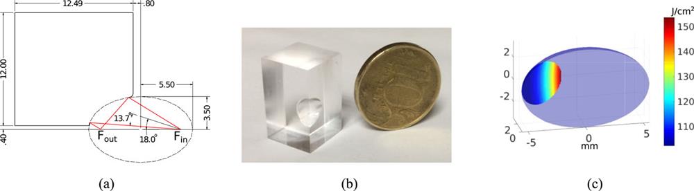
The EPMs designed for the PEARL campaign had a major axis of 5.5 mm and a minor axis of 3.5 mm, as shown in Fig. 1(a). The axis of the EPM was oriented at an incident angle of 18° with respect to the axis of the incoming beam focused by an f/2 parabola. Such a geometry transforms the input beam numerical aperture of 0.24 to an output numerical aperture of 0.75, i.e., an expected magnification of approximately 0.3.15 The EPM was machined by single point diamond turning from a poly(methyl methacrylate) (PMMA) substrate. An example of a machined EPM is shown in Fig. 1(b). For the geometry of the EPM described above, the expected fluence on the surface of the EPM was calculated when used with the PEARL laser (20 J, 60 fs) and is shown in Fig. 1(c). For an average fluence of about 110 J/cm2, we expect a reflectivity of about 60%–70%.19

Figure 1.(a) Sectional view of the EPM, depicting the geometry. The boundary of the laser beam path is shown in red. Fin and Fout are the input and output foci, respectively, of the EPM. (b) Image of a machined EPM placed next to a 10  coin of diameter 17.5 mm. (c) Expected fluence in J/cm2 on the surface of the EPM when used with the PEARL laser delivering 20 J on target. All dimensions are in millimeters.
B. Characterization of the EPM
The EPMs were characterized in a non-plasma regime on a test bench, where a collimated 5-cm-diameter helium-neon (HeNe) laser beam was focused by an f/2 OAP. The setup was similar to that described by Wilson et al.13 and the f-number of the parabola matched that of the PEARL facility. The focal spots produced by the EPM on the test bench and also on the PEARL laser facility are shown in Fig. 2. On the test bench, the measured magnification was about 0.48, significantly weaker than the predicted magnification of 0.3. To explain this discrepancy, we are currently developing optical models that calculate the exact solution for the focused intensity in the non-paraxial regime and also incorporate wavefront errors.20 On the PEARL facility, the observed magnification was 0.32. The corresponding increase in focused intensity that can be expected at the PEARL laser facility is about 8 when compared with operation of the laser with a normal f/2 OAP.11,13 When compared with a setup including a planar plasma mirror operating at a similar fluence, the expected enhancement of intensity is even higher: about 11.
Figure 2.Focal spot images normalized to peak intensity characterizing the performance of the EPMs. (a, b) Focal spot at the input (a) and output (b) of the EPM at the test bench. (c, d) Focal spots at the input (c) and (d) of the EPM at the PEARL laser facility as measured with low-power alignment beam. Field of view in all the images is 20 μm × 20 μm. The diameter of the full width at half maximum (FWHM) of the focal spot (ΦFWHM) and the fraction of energy enclosed within the FWHM (Eenc) are given in each image.
III. TARGET ALIGNMENT: SETUP AND RESULTS
A. Setup for alignment
The EPM and the target at the second focus were mounted on three-axis motorized linear stages with picomotor actuators (Model 8302 from Newport Corporation). The picomotors had a minimum step size of <30 nm and thus were very useful in precisely aligning the EPM and the target. The setup of the EPM and targetry stages is shown in Fig. 3. To align the front surface of the target, a retro-imaging system was assembled as shown in the figure. The laser light reflected from the front surface of the target was collected by the EPM. The pellicle beam splitter of thickness 5 μm then reflected the light, which was then focused by a retro-imaging lens onto a camera. The retro-imaging lens used in the setup had a focal length of 10 cm and an aperture of 7.5 cm. Such a high f-number lens allowed collection of all the light reflected from the pellicle and also ensured a desired magnification of about 10 by the lens within a reasonable space.
Figure 3.(a) Schematic of the setup used on the test bench to characterize the EPMs and benchmark the retro-alignment system. (b) Image of the setup, showing the physical layout of the components.
A similar setup for mounting the EPM and the target was also used for real laser-plasma experiments at the PEARL laser facility. The retro-imaging system was not installed at the PEARL facility, since only thin targets were shot, as discussed in the next subsection.
B. Target alignment by monitoring the near field
At the PEARL laser facility, 3-μm-thick Al foils were aligned with the output focus of the EPM. The target thickness was comparable to the Rayleigh length, and so the target was aligned by monitoring the near field after the EPM focus, as shown in Fig. 4(a). The microscope objective used for aligning the EPM was defocused and used as a lens for monitoring the near field. The near-field images obtained during the alignment procedure are shown in Fig. 4(b). As the target moves to intercept the incoming alignment beam, the shadow of the target is clearly visible in the near field. The direction from which the shadow enters the near-field image depends on whether the target is in front of or behind the focus. When a thin target is at the focus, the entire near-field profile diminishes simultaneously, as seen in [Fig. 4(b) right]. If the target thickness (3 μm in our case) is comparable to the Rayleigh length (expected to be around 3 μm for the output of the EPM at the PEARL facility), then two shadows approaching from either side on the near field can also be observed, and the shadow from the front side of the target [Fig. 4(b) center] can be distinguished from the shadow from the rear side of the target. On the PEARL facility, the front sides of the targets were aligned by monitoring the shadow from the front surface and placing the front surface at the focus. When shot with the full-energy beam, significant increase in the X rays and the maximum ion energy were measured as compared with normal OAP shots. These results will be described in subsequent publications.
Figure 4.Target alignment by monitoring the near field. (a) Schematic of the alignment method. (b) Near-field images during target alignment at the PEARL facility, showing the unobstructed near field, the shadow of the target moving from the right, and the shadow of the near field when the target was at the focus.
C. Target alignment by retro-imaging
The retro-imaging system, which is useful for aligning thicker targets, was assembled only on the test bench to benchmark its performance. A 0.8-μm-thick Al target was chosen to compare the two alignment procedures, since the target thickness was comparable to the Rayleigh length on the test bench [see Fig. 2(b)]. Initially, the target was aligned at the focus by monitoring the near field as described in the previous subsection. Subsequently, the axial location of the target was varied around this reference location. The longitudinal position of the target was measured absolutely using a Fabry-Pérot interferometer-based displacement sensor. Figure 5 shows the average brightness of the measured spot on the retro-imaging camera as a function of target displacement. The result shows that optimizing the target location for maximizing the average intensity measured in the retro-imaging camera can be used for aligning the target at the focus of the EPM within the Rayleigh length (approximately ±1 μm on the test bench). Such a retro-imaging system is planned to be implemented in future campaigns involving thicker targets with EPMs. It should be noted that on high-power facilities, the pellicle will have to be removed from the beam path before the full-power shot to avoid beam wavefront distortion due to nonlinear interaction of the high-intensity laser beam with the pellicle.
Figure 5.Average brightness of the spot measured on the retro-imaging camera as a function of the target displacement. A displacement of 0 corresponds to the reference location of the target where it was aligned by monitoring the near field.
Retro-imaging setups on existing facilities18 utilize a focusing OAP to collect light reflected from the front surface of the target. However, the retro-imaging setup described in this paper uses an EPM to collect the reflected light. The EPM in this configuration for collecting the reflected light acts like a high-magnification objective to create an image at the front focus, which is then imaged on the retro-imaging camera with a lens. The pellicle beam splitter used in the alignment process introduces significant wavefront errors in the reflected light, but, as is evident from Fig. 5, the alignment procedure is still robust.
IV. CONCLUSION
This paper has described the design of EPM for the PEARL laser facility and the retro-focus alignment procedure for aligning solid targets at the focus of the EPM. Measurement of the focal spots before and after the EPM on the PEARL facility yield an expected enhancement in intensity of about 8 during its operation. For a tightly focused beam at the output of the EPM, the Rayleigh length is extremely small (about 2 μm), and the front surfaces of solid targets have to be aligned within this precision. Two different methods for aligning the target at the focus of the EPM have been described here. The retro-imaging system that aligns the target by collecting the reflected light has been shown to have a precision of alignment within the Rayleigh length.
References
[1] S. V. Bulanov, G. A. Mourou, T. Tajima. Optics in the relativistic regime. Rev. Mod. Phys., 78, 309-371(2006).
[2] G. Chériaux, F. Druon, A. Fréneaux, P. Georges, C. Le Blanc, L. Martin, G. Mennerat, D. Papadopoulos, P. Ramirez, J. Zou et al. The Apollon 10 PW laser: Experimental and theoretical investigation of the temporal characteristics. High Power Laser Sci. Eng., 4, e34(2016).
[3] S. Bechet, S. Borneis, L. Brabec, M. Bučka, E. Chacon-Golcher, M. Ciappina, M. DeMarco, A. Fajstavr, K. Falk, E.-R. Garcia, J. Grosz, Y.-J. Gu, J.-C. Hernandez, M. Holec, P. Janečka, M. Jantač, M. Jirka, H. Kadlecova, D. Khikhlukha, O. Klimo, G. Korn, D. Kramer, D. Kumar, T. Laštovička, P. Lutoslawski, L. Morejon, V. Olšovcová, M. Rajdl, O. Renner, B. Rus, S. Singh, M. Šmid, M. Sokol, R. Versaci, R. Vrána, M. Vranic, J. Vyskočil, S. Weber, A. Wolf, Q. Yu. P3: An installation for high-energy density plasma physics and ultra-high intensity laser–matter interaction at eli-beamlines. Matter Radiat. Extremes, 2, 149-176(2017).
[4] D. L. Balabanski, S. Gales, F. Negoita, O. Tesileanu, C. A. Ur, D. Ursescu, N. V. Zamfir. New frontiers in nuclear physics with high-power lasers and brilliant monochromatic gamma beams. Phys. Scr., 91, 093004(2016).
[5] C. L. Arnold, M. Bocoum, F. Boehle, F. Calegari, F. Campi, D. Charalambidis, E. Cormier, T. Csizmadia, M. Devetta, M. Dumergue, B. Farkas, F. Frassetto, M. Füle, S. Haessler, C. M. Heyl, G. Iaquaniello, P. Johnsson, S. Kahaly, M. Kalashnikov, C. Kalpouzos, S. Kühn, A. L’Huillier, F. Lépine, R. Lopez-Martens, S. Maclot, B. Major, S. Mondal, E. Mÿnsson, M. Nisoli, K. Osvay, N. Papadakis, L. Poletto, P. Rudawski, G. Sansone, E. Skantzakis, S. Stagira, P. Tzallas, Z. Várallyay, K. Varjú, A. Vernier, C. Vozzi, H. Wikmark. The ELI-ALPS facility: The next generation of attosecond sources. J. Phys. B: At., Mol. Opt. Phys., 50, 132002(2017).
[6] S. V. Bulanov, T. Z. Esirkepov, D. Habs, F. Pegoraro, T. Tajima. Relativistic laser-matter interaction and relativistic laboratory astrophysics. Eur. Phys. J. D, 55, 483(2009).
[7] M. Borghesi, S. V. Bulanov, T. Esirkepov, G. Mourou, T. Tajima. Highly efficient relativistic-ion generation in the laser-piston regime. Phys. Rev. Lett., 92, 175003(2004).
[8] S. V. Bulanov, T. Z. Esirkepov, M. Kando, J. K. Koga, G. Korn, T. Nakamura. High-power γ-ray flash generation in ultraintense laser-plasma interactions. Phys. Rev. Lett., 108, 195001(2012).
[9] T. D. Arber, A. R. Bell, K. Bennett, C. S. Brady, R. Duclous, J. G. Kirk, C. P. Ridgers, A. P. L. Robinson. Dense electron-positron plasmas and ultraintense γ rays from laser-irradiated solids. Phys. Rev. Lett., 108, 165006(2012).
[10] S.-W. Bahk, V. Chvykov, G. Kalintchenko, A. Maksimchuk, G. A. Mourou, T. A. Planchon, P. Rousseau, V. Yanovsky. Generation and characterization of the highest laser intensities (1022 w/cm2). Opt. Lett., 29, 2837-2839(2004).
[11] P. Audebert, S. Buffechoux, J. Fuchs, R. Kodama, A. Kon, M. Nakatsutsumi. Fast focusing of short-pulse lasers by innovative plasma optics toward extreme intensity. Opt. Lett., 35, 2314-2316(2010).
[12] B. Atherton, P. Audebert, S. Buffechoux, S. N. Chen, J. Fuchs, M. Geissel, L. Gremillet, L. Hurd, M. Kimmel, R. Kodama, A. Kon, A. Korzhimanov, M. Nakatsutsumi, P. Rambo, M. Schollmeier, J. Schwarz, Y. Sentoku, M. Starodubtsev. Self-generated surface magnetic fields inhibit laser-driven sheath acceleration of high-energy protons. Nat. Commun., 9, 280(2018).
[13] C. Armstrong, D. C. Carroll, R. J. Clarke, R. J. Dance, R. J. Gray, S. J. Hawkes, M. King, P. McKenna, D. Neely, D. J. Robertson, R. Wilson. Ellipsoidal plasma mirror focusing of high power laser pulses to ultra-high intensities. Phys. Plasmas, 23, 033106(2016).
[14] C. Armstrong, C. Bourgenot, N. M. H. Butler, D. C. Carroll, R. J. Clarke, R. J. Dance, R. J. Gray, S. J. Hawkes, M. King, P. McKenna, D. Neely, D. J. Robertson, R. Wilson. Development of focusing plasma mirrors for ultraintense laser-driven particle and radiation sources. Quantum Beam Sci., 2, 1(2018).
[15] S. Buffechoux, Z. L. Chen, J. Fuchs, Z. Jin, R. Kodama, A. Kon, M. Nakatsutsumi. Geometrical optimization of an ellipsoidal plasma mirror toward tight focusing of ultra-intense laser pulse. J. Phys.: Conf. Ser., 244, 032008(2010).
[16] G. I. Freidman, V. N. Ginzburg, E. V. Katin, E. A. Khazanov, A. V. Kirsanov, V. V. Lozhkarev, G. A. Luchinin, A. N. Mal’shakov, M. A. Martyanov, O. V. Palashov, A. K. Poteomkin, A. M. Sergeev, A. A. Shaykin, I. V. Yakovlev. Compact 0.56 petawatt laser system based on optical parametric chirped pulse amplification in KD*P crystals. Laser Phys. Lett., 4, 421-427(2007).
[17] K. Burdonov, S. N. Chen, A. Eremeev, J. Fuchs, V. Ginzburg, E. Khazanov, A. Korzhimanov, A. Kuzmin, R. Osmanov, S. Pikuz, T. A. Pikuz, G. V. Pokrovskiy, G. Revet, I. Shaikin, A. Shaykin, A. Sladkov, A. Soloviev, M. Starodubtsev, I. Yakovlev. Experimental evidence for short-pulse laser heating of solid-density target to high bulk temperatures. Sci. Rep., 7, 12144(2017).
[18] D. C. Carroll, R. J. Clarke, M. Coury, F. Fiorini, P. Foster, J. Green, S. Green, R. Heathcote, P. McKenna, Z. Najmudin, H. Nakamura, D. Neely, R. Pattathil, K. Poder, G. Scott, M. Streeter, D. Symes. An assessment of the reproducibility of the gemini retro focusing system(2011).
[19] P. Audebert, G. Doumy, J. C. Gauthier, J.-P. Geindre, O. Gobert, P. Martin, M. Perdrix, F. Quéré, T. Wittmann. Complete characterization of a plasma mirror for the production of high-contrast ultraintense laser pulses. Phys. Rev. E, 69, 026402(2004).
[20] B. L. Garrec, T. M. Jeong, G. Korn, D. Margarone, T. Mocek, S. Weber. Spatio-temporal modification of femtosecond focal spot under tight focusing condition. Opt. Express, 23, 11641-11656(2015).

 coin of diameter 17.5 mm. (c) Expected fluence in J/cm2 on the surface of the EPM when used with the PEARL laser delivering 20 J on target. All dimensions are in millimeters.