• High Power Laser and Particle Beams
  • Vol. 34, Issue 5, 054001 (2022)
Haoyan Jia1、2, Senlin Huang1、2、*, Yi Jiao3, Jingyi Li3, Kexin Liu1、2, Shuai Liu1、2, Weihang Liu3, Zhongqi Liu1、2, Tianyun Long1、2、4, Weilun Qin4, and Sheng Zhao1、2
Author Affiliations
  • 1State Key Laboratory of Nuclear Physics and Technology, Peking University, Beijing 100871, China
  • 2Institute of Heavy Ion Physics, School of Physics, Peking University, Beijing 100871, China
  • 3Institute of High Energy Physics, Chinese Academy of Sciences, Beijing 100049, China
  • 4Deutsches Elektronen-Synchrotron (DESY), Hamburg 22603, Germany
  • show less
    DOI: 10.11884/HPLPB202234.220056 Cite this Article
    Haoyan Jia, Senlin Huang, Yi Jiao, Jingyi Li, Kexin Liu, Shuai Liu, Weihang Liu, Zhongqi Liu, Tianyun Long, Weilun Qin, Sheng Zhao. Research advances in ultrafast X-ray free-electron lasers[J]. High Power Laser and Particle Beams, 2022, 34(5): 054001 Copy Citation Text show less
    Working principle of a free-electron laser
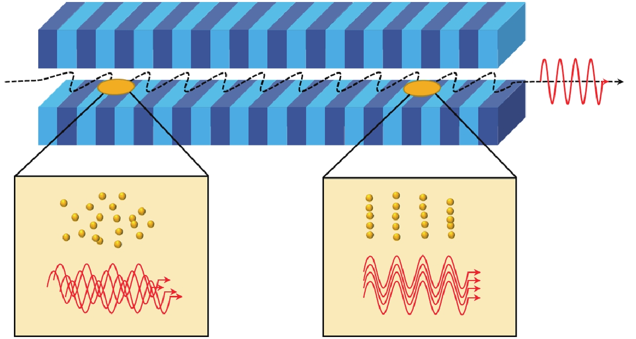
    Fig. 1. Working principle of a free-electron laser
    Schematic diagram of energy modulation scheme
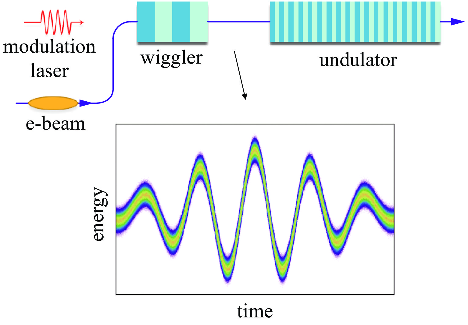
    Fig. 2. Schematic diagram of energy modulation scheme
    Schematic diagram of current modulation scheme
    Fig. 3. Schematic diagram of current modulation scheme
    Schematic illustration of the ESASE experiment at LCLS[47]
    Fig. 4. Schematic illustration of the ESASE experiment at LCLS[47]
    Schematic diagram of slotted foil scheme
    Fig. 5. Schematic diagram of slotted foil scheme
    Fresh-slice technique based on the transverse wakefields of a dechirper[68]
    Fig. 6. Fresh-slice technique based on the transverse wakefields of a dechirper[68]
    Schematic illustration of nonlinear bunch compression at LCLS[78]
    Fig. 7. Schematic illustration of nonlinear bunch compression at LCLS[78]
    Schematic diagram of the mode-locked FEL scheme proposed by Thompson et al.[80]
    Fig. 8. Schematic diagram of the mode-locked FEL scheme proposed by Thompson et al.[80]
    Schematic diagram of the mode-locked FEL scheme proposed by Dunning et al.[81]
    Fig. 9. Schematic diagram of the mode-locked FEL scheme proposed by Dunning et al.[81]
    Schematic diagram of attosecond soft X-ray cascade amplification scheme[87]
    Fig. 10. Schematic diagram of attosecond soft X-ray cascade amplification scheme[87]
    Schematic diagram of chirped microbunching scheme[88]
    Fig. 11. Schematic diagram of chirped microbunching scheme[88]
    Comparison of various ultrafast XFEL pulse generation schemes. The blue markers represent hard X-ray generation schemes and magenta markers represent soft X-ray generation schemes. The orange filled markers indicate the schemes have been validated on FEL facilities. The shaded blue area indicates the parameter space that can be achieved currently
    Fig. 12. Comparison of various ultrafast XFEL pulse generation schemes. The blue markers represent hard X-ray generation schemes and magenta markers represent soft X-ray generation schemes. The orange filled markers indicate the schemes have been validated on FEL facilities. The shaded blue area indicates the parameter space that can be achieved currently
    schemepulse duration (FWHM)/aspulse peak power/GWwavelength/photon energyreference
    energy modulation1000.0051 nm[29]
    30010.1 nm[28]
    3001000.15 nm[30]
    2001000.15 nm[31]
    400100900 eV/ 1100 eV[40]
    4001 0001.22 nm/ 2.48 nm[33]
    current modulation250400.15 nm[42]
    1002.30.15 nm[43]
    146580.1 nm[45]
    210250.15 nm[46]
    280100905 eV[47]
    250120940 eV[50]
    1 00039560 eV[51]
    emittance spoiling2 000108 keV[52]
    3 8002.51.1 nm[55]
    420305.6 keV[56]
    10 000301.5 keV[59]
    orbit control29 000120.15 nm[60]
    1151000.15 nm[61]
    5 000140670 eV[68]
    low charge bunch compression300100.15 nm[72]
    2 000201.5 nm[73]
    2 600101 keV[74]
    140350.15 nm[77]
    200505.6 keV[78]
    3264.37.36 keV[79]
    mode-locked FEL2360.15 nm[80]
    1.51.50.1 nm[81]
    cascade amplification2281 0000.1 nm[82]
    5001 0000.1 nm[83]
    536 60010 keV[84]
    1003000.1 nm[85]
    801 7000.15 nm[86]
    2605501.5 nm[87]
    chirped microbunching461.28.6 nm[88]
    Table 1. Main parameters of the schemes presented in Fig.12
    schemespectral range isolated pulse/ pulse train synchronization to optical laser high repetition frequency (MHz) hardware requirements and feasibility
    energy modulationall (soft X-ray to hard X-ray)isolated/trainyesno (self-modulation method-yes)high power external laser, need to add modulators
    current modulationallisolated/trainyesno (self-modulation method-yes)high power external laser, need to add modulators
    emittance spoiling slotted foilallisolatednononon-invasive hardware, can be used at any facilities
    optical shapingyesyesno additional hardware, can be used at any facilities
    orbit controlRF deflectorallisolatednoyesno additional hardware, can be used at any facilities
    laser modulationyesnohigh power external laser, need to add modulators
    transverse wakefieldnoyesadd dechirper before the undulator
    dispersion basednoyesno additional hardware, can be used at any facilities
    low charge bunch compressionallisolatednoyesno additional hardware, can be used at any facilities
    cascade amplification (based on slotted foil, orbit control, ESASE, the specific attributes are the same as above) allisolated/train————add chicane between undulators, need a dedicated line
    mode-locked FELalltrainyesnohigh power external laser and chicanes, need a dedicated line
    chirped microbunchingsoft X-rayisolatedyes——seed laser and modulators,need a dedicated line
    Table 2. A summary of various ultrafast XFEL pulse generation schemes
    Haoyan Jia, Senlin Huang, Yi Jiao, Jingyi Li, Kexin Liu, Shuai Liu, Weihang Liu, Zhongqi Liu, Tianyun Long, Weilun Qin, Sheng Zhao. Research advances in ultrafast X-ray free-electron lasers[J]. High Power Laser and Particle Beams, 2022, 34(5): 054001
    Download Citation