• Chinese Optics Letters
  • Vol. 13, Issue 11, 111101 (2015)
Zhengyang Li1、2、*, Haipin Lu1、2, and Xiangyan Yuan1、2
Author Affiliations
  • 1National Astronomical Observatories/Nanjing Institute of Astronomical Optics and Technology, Chinese Academy of Sciences, Nanjing 210042, China
  • 2Key Laboratory of Astronomical Optics & Technology, Nanjing Institute of Astronomical Optics and Technology, Chinese Academy of Sciences, Nanjing 210042, China
  • show less
    DOI: 10.3788/COL201513.111101 Cite this Article Set citation alerts
    Zhengyang Li, Haipin Lu, Xiangyan Yuan. Optical design for Antarctic Bright Star Survey Telescope[J]. Chinese Optics Letters, 2015, 13(11): 111101 Copy Citation Text show less
    Schematic drawing of R–C telescope.
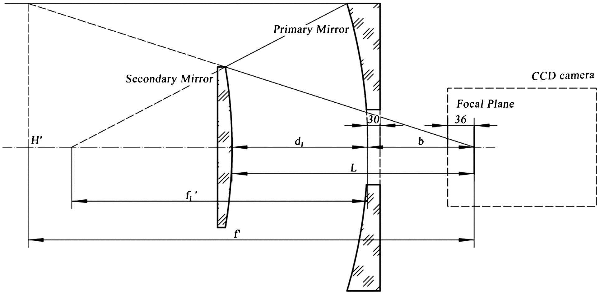
    Fig. 1. Schematic drawing of R–C telescope.
    BSST optical layout of open-band configuration. (The filter is located before the insulated window).
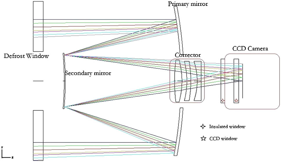
    Fig. 2. BSST optical layout of open-band configuration. (The filter is located before the insulated window).
    Image spot diagram of BSST (the box is 60 μm).
    Fig. 3. Image spot diagram of BSST (the box is 60 μm).
    Diffraction-encircled energy layout.
    Fig. 4. Diffraction-encircled energy layout.
    Resulting 80% encircled energy diameters.
    Fig. 5. Resulting 80% encircled energy diameters.
    Residual astigmatism and coma field behavior (the arrows on the maps show the amplitude and direction of the aberrations sampling from various fields).
    Fig. 6. Residual astigmatism and coma field behavior (the arrows on the maps show the amplitude and direction of the aberrations sampling from various fields).
    Astigmatism and coma field behavior of tilting secondary mirror around the CFP.
    Fig. 7. Astigmatism and coma field behavior of tilting secondary mirror around the CFP.
    Astigmatism and coma field behavior of translating secondary mirror.
    Fig. 8. Astigmatism and coma field behavior of translating secondary mirror.
    BSST image of 120 s exposure in the R band (1200 pixels×1200 pixels).
    Fig. 9. BSST image of 120 s exposure in the R band (1200pixels×1200pixels).
    Optical ElementRadius (mm)Conic CoefficientDistance (mm)
    Primary Mirror−800−1.33227.1
    Secondary Mirror−639.9−14.16357.1
    Table 1. Initial Optical Configuration of BSST
    Optical ElementRadius (mm)Conic CoefficientThickness (mm)Diameter (mm)Glass
    Defrost WindowInfinity20324Fused silica
    Infinity280
    Primary Mirror−800−1.519235315Zerodur
    Secondary Mirror−606−14.443222113Zerodur
    Lens 13581590Fused silica
    −159.910
    Lens 2−159.9884TF3
    −239.6613
    Lens 3−123.59880Fused silica
    Infinity40
    Insulated WindowInfinity890Fused silica
    Infinity18.5
    CCD WindowInfinity9.590Fused silica
    Infinity8
    Focal PlaneInfinity70
    Table 2. Optical Configuration of BSST
    FilterCentral Wavelength (nm)Bandwidth (nm)Transmission (%)Diameter (mm)
    B440100>5050
    V55090>7050
    R760250>7050
    Hα656.310>5025
    Hβ486.110>4025
    O–3500.710>6025
    Table 3. Parameters of Filters
    Manufactory Error Budget
    ItemsThickness (mm)Radius (mm)ConicNominal
    Primary±1mm±0.0001(−800; −1.519)
    Secondary±1mm±0.0001(−606; −14.443)
    Lens−0.10(15, 8, 8)
    Alignment Error Budget
    DOFDecenter (mm)TiltPosition (mm)
    PrimaryDATUM
    Secondary±0.06±1±0.4
    Corrector±0.1±3.6±0.4
    Lens Space±0.1
    Use Focal Length as Compensator
    Table 4. Tolerance Values of BSST
    Zhengyang Li, Haipin Lu, Xiangyan Yuan. Optical design for Antarctic Bright Star Survey Telescope[J]. Chinese Optics Letters, 2015, 13(11): 111101
    Download Citation