
Zhengyang Li, Haipin Lu, Xiangyan Yuan. Optical design for Antarctic Bright Star Survey Telescope[J]. Chinese Optics Letters, 2015, 13(11): 111101
- Chinese Optics Letters
- Vol. 13, Issue 11, 111101 (2015)
Abstract
Astronomers need advanced telescopes and qualified observation sites to observe the far and faint stars. The Antarctica plateau is widely considered to be an excellent astronomical site due to its superb seeing conditions[
Several Chinese wide-field Antarctic telescopes have been built. The first generation was the Chinese Small Telescope Array (CSTAR), which is composed of four identical telescopes with a 145 mm entrance pupil and a 20 square degrees field of view (FOV). CSTAR is fixed to point at the South Pole, and is mainly used for variable star detection and atmosphere extinction measurements. It was deployed in Antarctica in 2008 and its automatic operation continued for four consecutive winters[
The Antarctic Bright Star Survey Telescope (BSST), which mainly looks for exoplanets by searching with transit detection with a photometric precision of less than 0.6% magnitude, has a 300 mm aperture, an
Sign up for Chinese Optics Letters TOC. Get the latest issue of Chinese Optics Letters delivered right to you!Sign up now
There are several well-known optical systems for wide-field astronomical telescopes. The optical systems are the catadioptrics, such as CSTAR; the Schmidt and quasi-Schmidt types, such as AST3, and the Large Sky Area Multi-Object Fibre Spectroscopic Telescope (LAMOST). There are also the R–C two-mirror reflectors with correctors, such as the Visible and Infrared Survey Telescope for Astronomy (VISTA)[
The optics for CSTAR, AST3, and KDUST are not suitable for the BSST, since CSTAR has a larger light obstruction and a small back focal length with a fixed focal plane. AST3 is equipped with a camera located inside the optical tube, which is not convenient for installation or maintenance; the three-mirror systems are mainly for large telescopes with high resolutions. Considering the large dimension of selected CCD camera and the multiband filters switching mechanism, we decided to design an R–C telescope with a larger back focal length for the BSST.
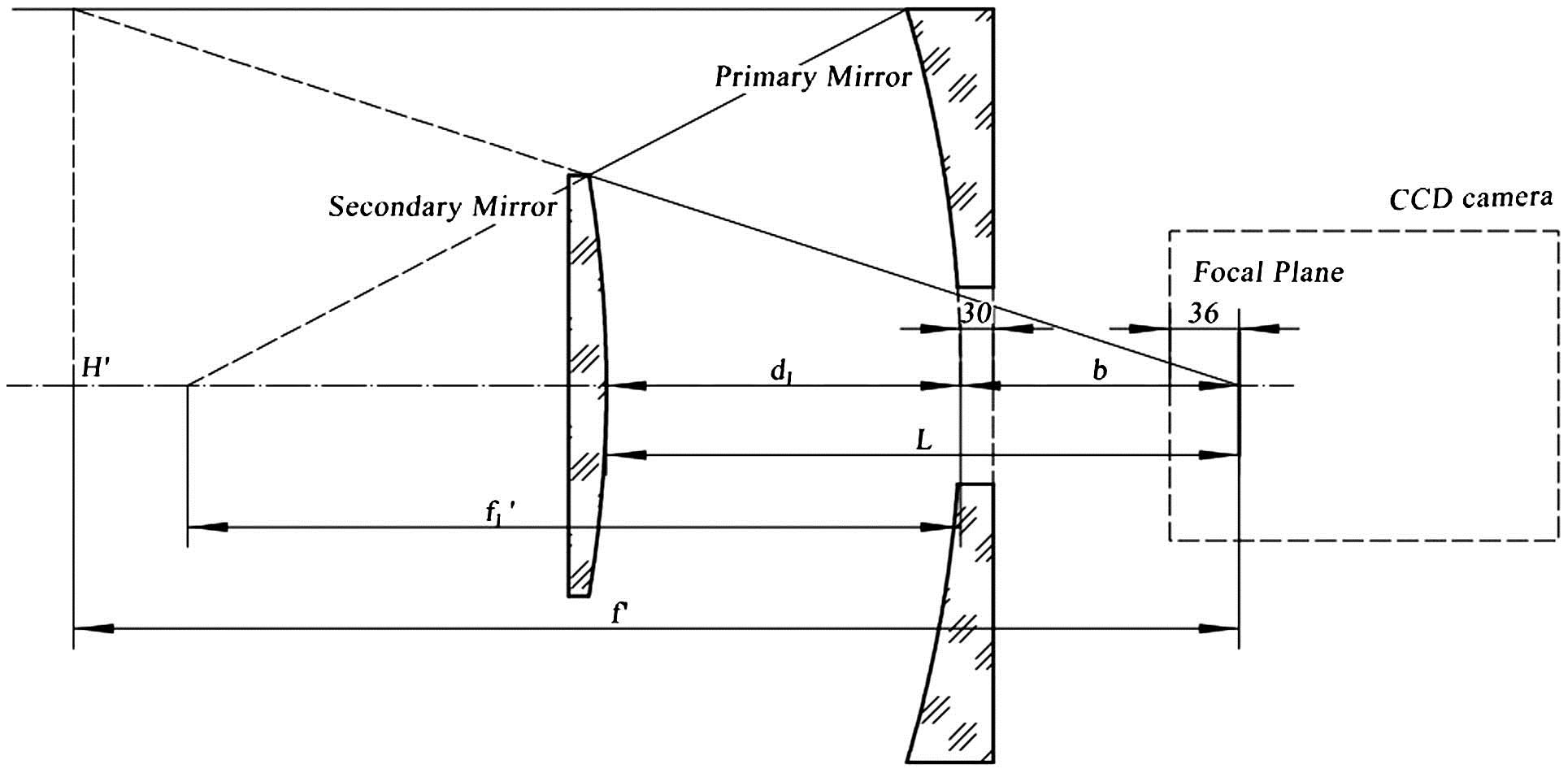
The optical layout of an R–C telescope is illustrated in Fig.
![]()
Figure 1.Schematic drawing of R–C telescope.
Referring to “Reflective Telescope Optics,” an axial obstruction ratio
Then,
The conic coefficients of the primary and secondary mirrors can be deduced based on the calculation of the Seidel aberrations coefficients, as
As
| Optical Element | Radius (mm) | Conic Coefficient | Distance (mm) |
|---|---|---|---|
| Primary Mirror | −800 | −1.33 | 227.1 |
| Secondary Mirror | −639.9 | −14.16 | 357.1 |
Table 1. Initial Optical Configuration of BSST
| Optical Element | Radius (mm) | Conic Coefficient | Thickness (mm) | Diameter (mm) | Glass |
|---|---|---|---|---|---|
| Defrost Window | Infinity | – | 20 | 324 | Fused silica |
| Infinity | – | 280 | |||
| Primary Mirror | −800 | −1.519 | 235 | 315 | Zerodur |
| Secondary Mirror | −606 | −14.443 | 222 | 113 | Zerodur |
| Lens 1 | 358 | – | 15 | 90 | Fused silica |
| −159.9 | – | 10 | |||
| Lens 2 | −159.9 | – | 8 | 84 | TF3 |
| −239.66 | – | 13 | |||
| Lens 3 | −123.59 | – | 8 | 80 | Fused silica |
| Infinity | – | 40 | |||
| Insulated Window | Infinity | – | 8 | 90 | Fused silica |
| Infinity | – | 18.5 | |||
| CCD Window | Infinity | – | 9.5 | 90 | Fused silica |
| Infinity | – | 8 | |||
| Focal Plane | Infinity | – | 70 | – |
Table 2. Optical Configuration of BSST
Then, we used the ZEMAX software for thorough optimization. Finally, an R–C telescope system with a three-lens corrector was obtained, which delivered a qualified performance for the wide field and the multiband system. The optical parameters are listed in Table
There are two critical problems for the special Antarctic telescopes, which will be operated at a temperature ranging from
Considering the dilemmas, we used a defrost window with an indium-tin-oxide film coating to seal the tube, which will be filled with nitrogen. The window’s frontier surface can be heated to protect the window from frosting up. Additionally, we selected a low-thermal-expansion optical material, such as Zerodur or fused silica glass, to minimize the thermal effect. However, we had to use a TF3 material for to correct the chromatic aberration.
For the open-band (0.36–1.014 μm) configuration shown in Fig.
| Central Wavelength (nm) | ||||
|---|---|---|---|---|
| B | 440 | 100 | 50 | |
| V | 550 | 90 | 50 | |
| R | 760 | 250 | 50 | |
| 656.3 | 10 | 25 | ||
| 486.1 | 10 | 25 | ||
| O–3 | 500.7 | 10 | 25 |
Table 3. Parameters of Filters
![]()
Figure 2.BSST optical layout of open-band configuration. (The filter is located before the insulated window).
For the open-band configuration, the optical performances are illustrated by Figs.
![]()
Figure 3.Image spot diagram of BSST (the box is 60 μm).
![]()
Figure 4.Diffraction-encircled energy layout.
By using at least three different materials, an apochromatic system can possibly be achieved with less coma and chromatism aberrations[
When we finished with the design, an error budget analysis helped us to build a reasonably priced system. During the tolerance analysis procedure, we defined a focal compensator, and used the Monte–Carlo simulation to predict the statistical effects by simulating more than 300 random systems that meet all of the tolerance values, which are listed in Table
| Manufactory Error Budget | ||||
|---|---|---|---|---|
| Items | Thickness (mm) | Radius (mm) | Conic | Nominal |
| Primary | – | (−800; −1.519) | ||
| Secondary | – | (−606; −14.443) | ||
| Lens | −0.1 | – | 0 | (15, 8, 8) |
| Alignment Error Budget | ||||
| DOF | Decenter (mm) | Tilt | Position (mm) | |
| Primary | DATUM | |||
| Secondary | ||||
| Corrector | ||||
| Lens Space | – | – | ||
| Use Focal Length as Compensator | ||||
Table 4. Tolerance Values of BSST
![]()
Figure 5.Resulting 80% encircled energy diameters.
When assembling the BSST in the laboratory, we can predict the misalignment states with the aberration measurements. The optical performance of a misaligned R–C telescope can be described as resulting in field-dependent astigmatism and a field-uniform coma[
![]()
Figure 6.Residual astigmatism and coma field behavior (the arrows on the maps show the amplitude and direction of the aberrations sampling from various fields).
![]()
Figure 7.Astigmatism and coma field behavior of tilting secondary mirror around the CFP.
![]()
Figure 8.Astigmatism and coma field behavior of translating secondary mirror.
The field behaviors of the astigmatism and coma indicate that we can minimize the astigmatism by secondary tilting and lower the chance of a coma by secondary translating separately[
In April 2015, the telescope completed its test observation at Gaomeigu station (Yunnan Observatory) before we transported the BSST to Zhongshan Station in Antarctica. Figure
![]()
Figure 9.BSST image of 120 s exposure in the
The Antarctic telescopes are special, and the experiences of the CSTAR and AST3 projects provide us with many things to consider when designing and building the BSST. This Letter presents the optical system design, tolerance analysis, and alignment metrology of the unique and powerful Antarctic BBST. Eventually, the test observation results indicate that the BSST is a superior telescope with a 4.8° FOV and 0.36–1.014 μm wavelength coverage. The BSST is capable of delivering a qualified performance with a limiting magnitude of at least 17 m and a photometric precision of 0.4% m, which should convince astronomers of its ability to make significant discoveries in the search for exoplanets when it is deployed in Antarctica.
References
[1] J. S. Lawrence, M. C. B. Ashley, A. Tokovinin, T. Travouillon. Nature, 431, 278(2004).
[2] G. Liu, X. Yuan. Acta Astron. Sin., 50, 224(2009).
[3] X. Yuan, D. Su. MNRAS, 424, 23(2012).
[5] C. F. Claver, L. Seppala, M. Liang, K. Gilmore, W. Gressler, V. Krabbendam, D. Niell, S. Oliver, J. Sebag. Performance and Analysis of the LSST Optical System(2010).
[6] X. Yuan, X. Cui, D. Su, Y. Zhu, L. Wang, B. Gu, X. Gong, X. Li. Proc. Int. Astron. Union., 8, 271(2013).
[7] X. Hu, W. Wang, Q. Hu, X. Lei, Q. Wei, Y. Liu, J. Wang. Chin. Opt. Lett., 12, 072901(2014).
[8] R. Wilson. Reflecting Telescope Optics I(2004).
[9] Q. Yang, B. Zhao, R. Zhou. Chin. Opt. Lett., 6, 146(2008).
[10] K. Thompson. J. Opt. Soc. Am A, 22, 1389(2005).
[11] Z. Li, X. Yuan. Proc. SPIE, 9150, 91501Y(2014).

Set citation alerts for the article
Please enter your email address
© Copyright 2018-2021 | Chinese Laser Press. All Rights Reserved 沪ICP备15018463号-20