• Acta Optica Sinica
  • Vol. 41, Issue 9, 0922002 (2021)
Yuan Ju1, Chunzhu Zhao2、**, Mingxu Piao1、*, Yu Guo1, Shanshan Gu1, and Hanqing Zheng1
Author Affiliations
  • 1School of Opto-Electronic Engineering, Changchun University of Science and Technology, Changchun, Jilin 130022, China
  • 2Institute of Molecular Medicine, Peking University, Beijing 100871, China
  • show less
    DOI: 10.3788/AOS202141.0922002 Cite this Article Set citation alerts
    Yuan Ju, Chunzhu Zhao, Mingxu Piao, Yu Guo, Shanshan Gu, Hanqing Zheng. Dynamic Aberration Correction for Conformal Dome Based on Free-Form Lens Array[J]. Acta Optica Sinica, 2021, 41(9): 0922002 Copy Citation Text show less
    Schematic diagram of the conformal dome aberration correction based on free-form lens array
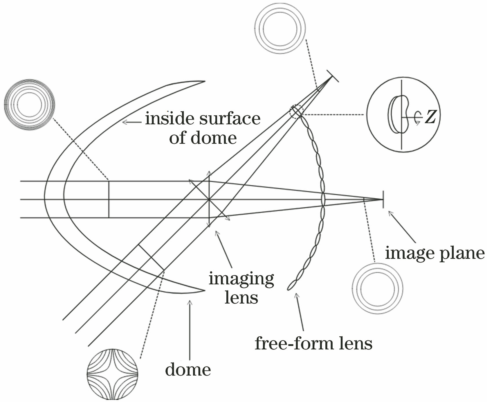
    Fig. 1. Schematic diagram of the conformal dome aberration correction based on free-form lens array
    Initial structure of the LA superposition of the conformal optical system
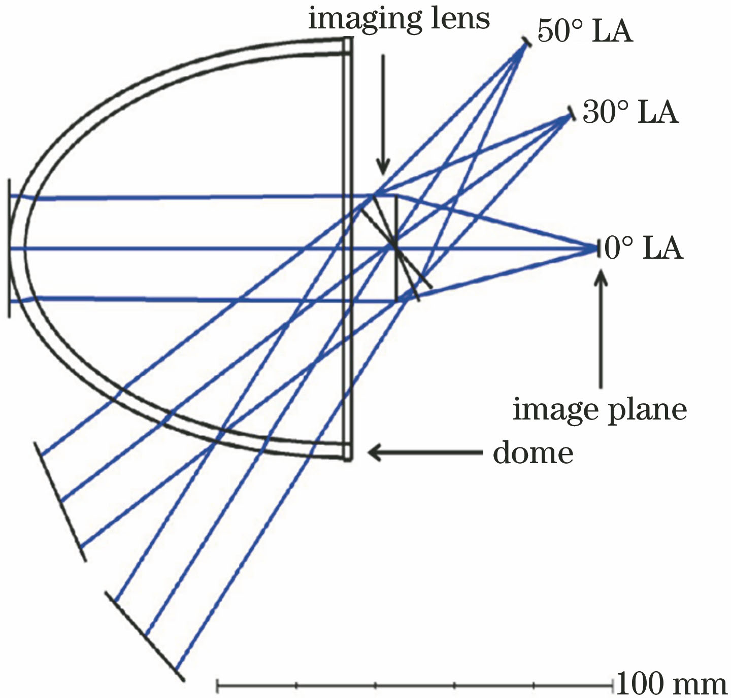
    Fig. 2. Initial structure of the LA superposition of the conformal optical system
    Relationship between the Zernike coefficient of the initial conformal optical system and LA. (a) Z1-Z9; (b) Z10-Z18
    Fig. 3. Relationship between the Zernike coefficient of the initial conformal optical system and LA. (a) Z1-Z9; (b) Z10-Z18
    Relationship between Zernike coefficient and LA on the inner surface of the dome after correction. (a) Z1-Z9; (b) Z10-Z18
    Fig. 4. Relationship between Zernike coefficient and LA on the inner surface of the dome after correction. (a) Z1-Z9; (b) Z10-Z18
    Structure of the conformal optical system. (a) Lens array when the LA is 0°-50° in the Y-Z plane; (b) optical path of the imaging channel of the adjacent lens array
    Fig. 5. Structure of the conformal optical system. (a) Lens array when the LA is 0°-50° in the Y-Z plane; (b) optical path of the imaging channel of the adjacent lens array
    Curvatures of the surfaces of different LA lens arrays after optimization
    Fig. 6. Curvatures of the surfaces of different LA lens arrays after optimization
    Relationship between the Zernike coefficient and LA of the conformal optical system after adding lens array. (a) Z1-Z9; (b) Z10-Z18
    Fig. 7. Relationship between the Zernike coefficient and LA of the conformal optical system after adding lens array. (a) Z1-Z9; (b) Z10-Z18
    Scanning angle of rotation of each lens element around the Z axis
    Fig. 8. Scanning angle of rotation of each lens element around the Z axis
    Curvatures of each LA lens array surface after Zernike polynomial surface shape optimization
    Fig. 9. Curvatures of each LA lens array surface after Zernike polynomial surface shape optimization
    Change curves of Zernike coefficients after surface shape optimization. (a) Front surface of the array; (b) rear surface of the array
    Fig. 10. Change curves of Zernike coefficients after surface shape optimization. (a) Front surface of the array; (b) rear surface of the array
    Relationship between Zernike coefficient and LA of conformal optical system after surface shape optimization. (a) Z1-Z9; (b) Z10-Z18
    Fig. 11. Relationship between Zernike coefficient and LA of conformal optical system after surface shape optimization. (a) Z1-Z9; (b) Z10-Z18
    MTF of the optical system at different LA. (a) 0°; (b) 10°; (c) 20°; (d) 30°; (e) 40°; (f) 50°
    Fig. 12. MTF of the optical system at different LA. (a) 0°; (b) 10°; (c) 20°; (d) 30°; (e) 40°; (f) 50°
    Structure of the two-dimensional lens array
    Fig. 13. Structure of the two-dimensional lens array
    Structure of a two-dimensional lens array conformal optical system. (a) Front surface; (b) rear surface
    Fig. 14. Structure of a two-dimensional lens array conformal optical system. (a) Front surface; (b) rear surface
    Surface vector height of a two-dimensional free-form lens array. (a) Front surface; (b) rear surface
    Fig. 15. Surface vector height of a two-dimensional free-form lens array. (a) Front surface; (b) rear surface
    Conformal dome optical system based on a two-dimensional free-form lens array. (a) Front surface; (b) rear surface
    Fig. 16. Conformal dome optical system based on a two-dimensional free-form lens array. (a) Front surface; (b) rear surface
    Yuan Ju, Chunzhu Zhao, Mingxu Piao, Yu Guo, Shanshan Gu, Hanqing Zheng. Dynamic Aberration Correction for Conformal Dome Based on Free-Form Lens Array[J]. Acta Optica Sinica, 2021, 41(9): 0922002
    Download Citation