Light carries energy and momentum, laying the physical foundation of optical manipulation that has facilitated advances in myriad scientific disciplines, ranging from biochemistry and robotics to quantum physics. Utilizing the momentum of light, optical tweezers have exemplified elegant light–matter interactions in which mechanical and optical momenta can be interchanged, whose effects are the most pronounced on micro and nano objects in fluid suspensions. In solid domains, the same momentum transfer becomes futile in the face of dramatically increased adhesion force. Effective implementation of optical manipulation should thereupon switch to the “energy” channel by involving auxiliary physical fields, which also coincides with the irresistible trend of enriching actuation mechanisms beyond sole reliance on light-momentum-based optical force. From this perspective, this review covers the developments of optical manipulation in schemes of both momentum and energy transfer, and we have correspondingly selected representative techniques to present. Theoretical analyses are provided at the beginning of this review followed by experimental embodiments, with special emphasis on the contrast between mechanisms and the practical realization of optical manipulation in fluid and solid domains.
Light can exert forces (torques) on objects during the light–matter interaction and therefore is used as an optical manipulation tool for micro/nano-objects. As early as 1619, the concept of “force of light” was first proposed by Johannes Kepler in an attempt to explain the phenomenon that when a comet enters the solar system, its tail is always deflected away from the sun[1]. The underlying mechanism was later summarized by Maxwell’s electromagnetic theory, which states that light, though electromagnetic waves, carries momentum[2]. Accounting for forces that stem from the momentum exchange between the radiation field and the interactive matter, the force of light belongs to a general phenomenon known as the “radiation force”[3–5]. For the sake of brevity, the electromagnetic radiation force has now been more frequently addressed as the “optical force.” Specifically, the most vivid picture of optical force should be the case that when a beam of light is fired at a reflecting mirror, a pushing force is generated as the consequence of the momentum transfer from photons to the mirror, as the direction of light momentum is reversed upon reflection. However, due to the “extreme minuteness” of the optical force, John Henry Poynting deemed its application untenable in driving mechanical locomotion in terrestrial scenarios[6]. The potential of light momentum, or rather, the optical force, was not truly appreciated until the advent of the laser and the landmark invention of optical tweezers by Arthur Ashkin, who demonstrated optical trapping and manipulation of micro/nano particles, living cells, and molecules using optical force in fluidic environments[7,8]. By virtue of his remarkable work, Ashkin was awarded the Nobel Prize in Physics in 2018. His experiments also formed the basis of another Nobel Prize in Physics in 1997 for Steven Chu’s work on the optical cooling of atoms, showing that optical manipulation is a fascinating field in fostering scientific explorations at the “bottom” (quoting Richard Feynman’s speech[9]).
In the macro regime, a semi-quantitative estimation of the optical force exerted on a reflective surface is , where is the optical power, the reflectance, and the speed of light[7,10]. The expression of optical force shares the general traits of radiation force, proportional to the incident power divided by the wave velocity[3,4]. Correspondingly, for a light beam of power , the optical force is 1 nN, and that is still under the assumption of perfect reflection (). A force of such order of magnitude can easily be eclipsed by gravitation or even environmental perturbations at the macroscale, which somehow confirms the assertion of Poynting[10,11]. In the micro regime, considering that not all incident photons would fall within the target volume, it is the local light intensity (i.e., the Poynting power density) rather than the optical power that is of more immediate concern. Hence, the notion of “pressure” should be adopted instead, as in “radiation pressure” in early literatures[7,11,12], given by , where denotes the light field intensity[11,13].
For micrometer or sub-wavelength objects, a -scale optical force would become relevant in that it generates roughly 102−105 times the gravitational acceleration, which thus sets it apart from that at the macroscale. To ensure optical force reaches piconewton, which, from an empirical standpoint, has become the basic standard to implement stable trapping in optical tweezers, coherent light sources and high-numerical-aperture (NA) objectives should be employed that condense the incident light power within diffraction-limited spots and maintain the local light intensity as high as , and that is where the role of lasers and Ashkin’s design of the optical trap apparatus should be appreciated. Over the past few decades, continuous efforts have been made in enhancing the optical force attainable at micro/nano scales, successful examples including the incorporation of plasmonic[14,15] and resonance dielectric structures[16,17]. Yet the diffraction and speed of light (or the dispersion relation of photons) have fundamentally set the limit of optical force, which typically could not surpass even with rather strong field localization. Because of its magnitude, optical force has mainly been exploited in fluidic environments, where the significance of optical force is still prominent against countering effects such as Brownian diffusion and viscous drag.
Sign up for Photonics Insights TOC. Get the latest issue of Photonics Insights delivered right to you!Sign up now
To implement optical manipulation in the fluidic domain, aside from acquiring mechanical momentum directly from light momentum, an indirect route can be taken, which requires making use of the hydrodynamic surroundings. A representative example is the photophoretic force, denoting the migration of light-absorptive particles in gaseous suspensions[18,19]. Specifically, the generation of photophoretic force demands the existence of gas molecules, the collisions between which and the particle create a net force pointing opposite to the particle’s surface temperature gradient. Assuming a particle with zero thermal conductivity, the relevance of the gas pressure greatly diminishes, and the photophoretic force can be estimated as , where denotes the conversion efficiency from light energy to the thermal energy of surrounding air molecules, the accessible optical power in the target region, and the average gas molecular velocity[20–22]. The Maxwell’s law of velocity distribution has determined to be in the range of at room temperature, considerably smaller than the traveling speed of light. Consequently, for strongly absorbing and poorly thermal conducting particles, the effects of optical force could be overwhelmed by photophoretic force, rendering the latter a destructive factor in optical-force-based manipulation; while from another perspective, by interfacing the energy channel of light, the photophoretic force, together with other heat-mediated and fluidic-assisted effects, e.g., the Ludwig–Soret effects[23] and electrothermoplasmonic flow[24,25], provides alternative options to enable robust, long-distance and multi-mode optical manipulation with relaxed requirements upon local light intensity. Notably, in these schemes, instead of imparting forces directly on target objects, light, through photothermal effects, will first induce flows of hydrodynamic environments by imposing specific temperature profiles, which then give rise to the concomitant locomotion of suspended particles.
Fluidic environments have proved to be golden testing grounds for optical manipulation, while an inevitable trend is to further extend its capability to the solid domain, the exploration of which is doomed to be difficult because of two major challenges: (1) the adhesive and friction forces reach the order of μ, causing a tremendous scale gap with the optical force[26], and (2) the fluid-assisted effects are inaccessible on dry surfaces due to the lack of fluidity and the no-slip condition along solid boundaries[27].
To meet the challenges, a tactful resolution is to “inflict fluidity” in solid environments through photothermal effects, which bypasses the adhesion and additionally creates auxiliary hydrodynamic flows for mass transportation. In the meantime, it is vital that proper drives should be found that are both adequate in magnitude and compatible with solid environments. Still interfacing the energy channel of light, researchers in the early 1990s demonstrated the detachment and propulsion of adhering particulates via pulsed light illumination on absorbing substrates, the technique of which has been widely exploited in semiconductor surface cleaning[28,29]. As the result of opto-thermo-mechanical muliphysics coupling, the impulsive thermal expansion/compression of the substrate translates into surface acoustic waves, and the particulates immersed in the acoustic momentum field experience the acoustic radiation force calculated as , where denotes the photoacoustic conversion efficiency, the transient optical power of the pulsed incident light, and the sound speed in elastic media (e.g., of bulk silicon is )[30,31]. Denoting the momentum exchange between the acoustic field and the particle, the acoustic radiation force is the acoustic counterpart of the optical force (i.e., electromagnetic radiation force) and possesses the same fundamental expression, which, owing to the moderate sound speed as opposed to that of light, is of considerably larger magnitude at the same input power. Typically, acoustic waves are excited by applying electric signals on piezoelectric substrates and have been utilized for the construction of acoustic tweezers and enabling acoustic sorting and assembly of particles[3,32,33]. The fact that acoustic waves can also be excited via pulsed light illumination provides opportunity for optical manipulation extending to the solid domain[34]. Specifically, apart from its large photoacoustic conversion efficiency, the photothermal process of pulsed light features enormous transient energy deposition (large ). At a moderate pulse energy of , it is capable of generating transient acceleration of adhering particulates sufficient in escaping from the adhesive force[28,29].
Inspired by the working principles of machineries, a series of intriguing work has reported multi-degree-of-freedom locomotion of micrometer-sized actuators in dry adhesive environments based on an internal force-driven mechanism[5,35–38]. Interestingly, instead of endeavoring to find the proper driving forces comparable to the μ-scale adhesive/friction forces, which is admittedly difficult when the force of interest belongs to the “external force,” researchers took a different approach by inducing the impulsive deformation of actuators via pulsed light illumination. The deformation, though also in the form of acoustic waves, functions effectively as the internal force in facilitating the locomotion on frictional substrates, in analogy to the operation of machineries or the crawling of earthworms via internal coordination rather than external assistances. Owing to its internal force nature, light-induced deformation effects may not be explicitly expressed as in the form of optical force, photophoretic force, or acoustic radiation force, which are all external forces (see Table 1 for comparison). Following the same mechanism, flexible polymers or hydrogels could be constructed into light-addressable soft robotics with delicate design and assembly, which take on more familiar modalities outside the framework of acoustic waves. Comparatively, their deformations are more profound and should be completed within considerably longer time windows in a semi-steady state, which are typically driven by modulated CW light.
Properties of Different Light-Induced Forces/Effects.
Optical ForcePhotophoretic ForceLight-Induced Acoustic Radiation ForceLight-Induced Deformation EffectsMechanismLight momentum channelLight energy channelLight energy channelLight energy channelMomentum transfer between light and objects1. Photothermal effects1. Opto-thermo-mechanical coupling1. Opto-thermo-mechanical coupling2. Nonuniform collisions between the particle and air molecules2. Momentum transfer between acoustic waves and objects2. Internal force-driven mechanismIntuitive expressionaMagnitudeb∼pN–nN or beyondμμWorking environmentFluid domainFluid domainSolid domainSolid domain
Approximate expressions for intuitive understanding of the scale of corresponding forces. The definitions of related variables can be found in the main text.
Magnitudes of forces when applied to micro/nano objects.
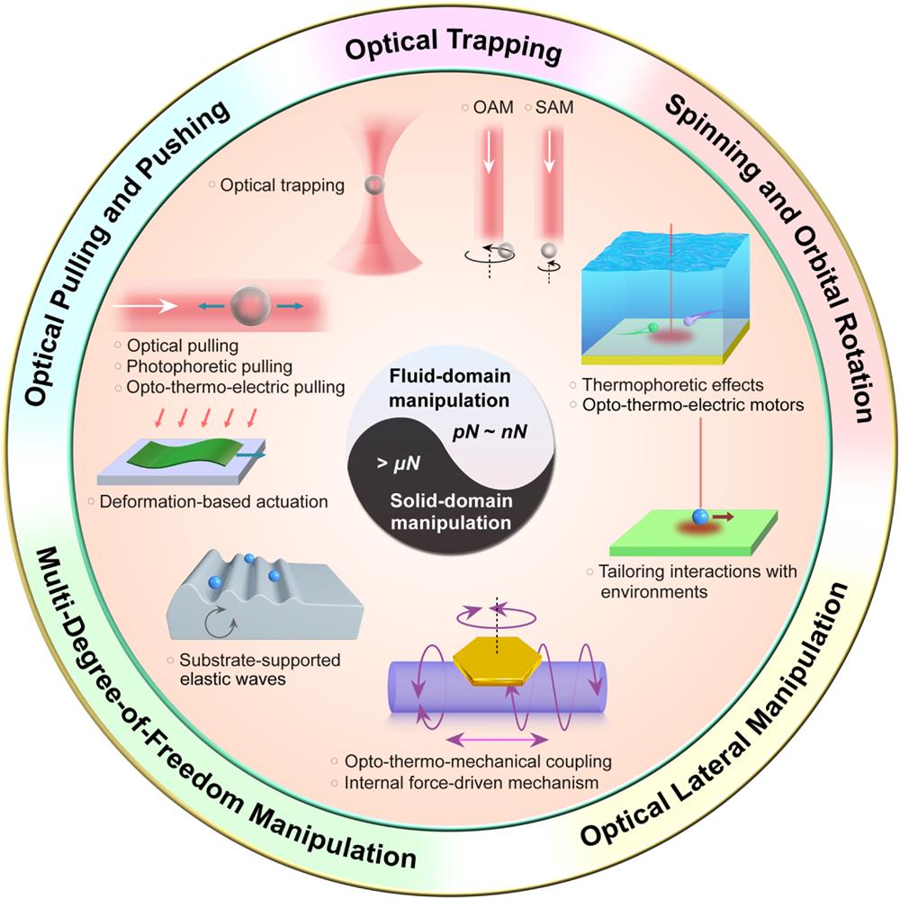
As the opening salvo of this review, the above discussion is aimed to introduce the topic of optical manipulation and provide some general ideas about its actual implementation in fluidic and solid domains from the perspective of different light-induced forces/effects (Table 1). A more comprehensive overview will be provided in the following content, which is also summarized in Fig. 1. The organization of this review is as follows. In Sec. 2, we introduce the physical mechanisms and theories of several light-induced forces involved in optical manipulation processes, including the optical force/torque and the thermophoretic force in fluidic environments and light-induced deformation effects in solid environments. Next, revolving around the fluid as the operational environment, we revisit representative optical manipulation techniques in Sec. 3 and categorize them by the locomotion degree of freedom. In Sec. 4, techniques adapted to the solid domain optical manipulation are presented, which are classified with respect to the working mechanisms. In Sec. 5, we selectively introduce several applications regarding historically important or emerging topics. Finally, we conclude the main contribution of this review, and envision future directions in the field of optical manipulation.
Figure 1.Overview of optical manipulations in fluid domains and solid domains. Optical manipulations generally include optical trapping, pulling and pushing, lateral manipulation, spinning and orbital rotating, and multi-degree-of-freedom manipulation. Optical manipulations in fluid domains are based on light directly induced forces (i.e., optical gradient forces and optical scattering forces) and indirectly induced forces (e.g., photophoretic force and thermal-electric mediated forces) whose amplitudes are typically of the order from pN to nN. In contrast, optical manipulations on solid surfaces need driving forces larger than μN to overcome the tremendous adhesion/friction forces in micro/nano scales. Examples include opto-thermal-elastic forces, pulsed light-induced forces, light-induced forces generated from photoactive polymers, and photothermal deformation-based actuations.
In Sec. 1, we introduce four types of light-induced forces (effects) that can be exploited in optical manipulation, namely, the optical force, photophoretic force, light-induced acoustic radiation force, and deformation effects, the latter two both originating from opto-thermo-mechanical coupling. For the sake of clarity, we denote that in what follows in this review, optical force (also optical torque) refers exclusively to the force (or torque) arising from momentum transfer between the light field and matter, i.e., electromagnetic radiation force (torque), not to be confused as the general term for all light-induced forces. Moreover, the photophoretic force is a sub-branch under a larger category termed “thermophoretic force,” describing the transmission of small particles in both air (i.e., photophoretic force) and liquid (i.e., Ludwig–Soret effects) media, the differentiation between which will be made clear in Sec. 2.2. Acoustic-wave-related forces, on the other hand, consist of both the external force, as in acoustic radiation force, which stems from acoustic waves excited in substrates, and internal force in the form of light-induced deformation effects (acoustic waves) in actuators.
In this section, physical mechanisms and theories are presented about three representative forces (effects). In Sec. 2.1, the origin and theoretical derivation of optical force and torque will be first provided (from Secs. 2.1.1–2.1.4), followed by a brief introduction of the measurement methods (Sec. 2.1.5) of optical force, which is of great practical significance in optical tweezer experiments. Section 2.2 is devoted to introducing the thermophoretic force in air (Sec. 2.2.1) and liquid suspensions (Sec. 2.2.2), which are associated with different interpretations and analytical treatments. Given that the acoustic radiation force is adequately illustrated in Sec. 1, Sec. 2.3 mainly focuses on the part of the internal force, that is, specifically, the light-induced deformation effects. Note that we have left out “force” in addressing these effects to avoid their being miscomprehended as external forces.
2.1 Optical Force and Optical Torque
2.1.1 Physics origin
Due to the fundamental homogeneity and isotropy of space, closed physical systems carry two conserved quantities termed as linear and angular momenta[39]. Unsurprisingly, light also has linear and angular momenta; thus, it could exert force and torque on physical objects via light–matter interactions, such as reflection, refraction, scattering, and absorbing processes. The earliest realization of the existence of the linear momentum of light can be tracked back to 1619, when Kepler speculated that the pressure of sunlight pushes comet tails away from the Sun. Two centuries later, after the establishment of his famous electromagnetic theory, Maxwell correctly calculated the pressure of solar radiation on the Earth’s surface[40], the similar physics of which confirms Kepler’s speculation. By analog with a point particle in classical mechanics, it is straightforward to argue that a light beam with a linear momentum should carry an angular momentum , the so-called external angular momentum, which depends on the choice of the origin of the coordinate system. However, light is beyond this expectation. Besides the external angular momentum, light possibly carries intrinsic angular momentum independent of the choice of the coordinate system. In 1909, Poynting first pointed out that circularly polarized light of angular frequency carries angular momentum, the ratio between which and light energy is , where or for left- and right-circular polarization, respectively[41]. This polarization associated angular momentum is nowadays called spin angular momentum (SAM) of light. In addition to SAM, light can also carry orbital angular momentum (OAM), the discovery of which was in 1992 by Allen et al., who recognized that a Laguerre–Gaussian mode with a twist phase surface has OAM equal to [42].
At the fundamental micro-level, the force and the torque exerted by light can be computed by summarizing the Lorentz force () on individual atoms without referring to the concept of light momentum. However, this approach is formally inconvenient because electromagnetic fields at atoms can be precisely obtained only by using microscopic electromagnetism, in which bound atomic charge densities and convective free-carrier currents are treated as elementary sources in free-space Maxwell equations. Instead, a convenient, widely accepted way is to apply macroscopic electromagnetism[43], which neglects atomic features and considers average electromagnetic fields at scales well beyond atomic sizes. The linear and angular momenta of light are then prioritized as the basic concepts, the dynamic evolutions of which directly give the force and the torque just as in classical mechanics.
2.1.2 Electromagnetic energy–momentum tensor
In macroscopic electromagnetism, the electromagnetic energy–momentum tensor, a matrix concerning the densities and fluxes of the electromagnetic energy and momentum, is a tool to characterize the energy–momentum dynamics and derive the optical force and torque. However, even though macroscopic electromagnetism is generally considered well developed, rival expressions of the electromagnetic energy–momentum tensor surprisingly exist, each supported with compelling evidences and arguments[44]. Among the various expressions, two of the most famous are arguably the so-called Minkowski[45] and Abraham tensors[46], which were both introduced in the first decade of the 20th century. Specifically, the Minkowski tensor, denoted by , is given by Here, is the velocity of light in vacuum; and denote the electromagnetic (EM) energy density and energy flux density, respectively; and represent the linear momentum density and flux density tensor, respectively. Note that the negative of the momentum flux density tensor, , is also called the Maxwell stress tensor. In a lossless, non-dispersive and reciprocal medium, the expressions of , , , and are given by where denotes the outer product, and is the identity tensor. The momentum flux density tensor, , is symmetric due to the reciprocity with ɛɛ and (ɛ and are material permittivity and permeability tensors, respectively, and the transpose operation applied to a tensor ). The energy–momentum tensor is, however, asymmetric since unless in free space. The asymmetry of the Minkowski tensor was criticized considerably, since it violates the conservation of angular momentum[2]. To fix this issue, the Abraham tensor was proposed with the momentum density modified to which equals , thus recovering the symmetry of the energy–momentum tensor.
The contradiction between the Minkowski and Abraham energy–momentum tensors [or more precisely, the Minkowski and Abraham momentum densities, cf. Eqs. (2.c) and (3)] is confusing, since it leads to the indefiniteness of the light momentum that is, however, to have a unique expression due to its physical reality. To explicitly illustrate the predictive difference between the Minkowski and Abraham formulations, we consider that a light wave packet with volume and a linear momentum transmits from free space into a dielectric medium with refractive index . Further, we assume that the dielectric medium is transparent, so that the reflection is negligible, and, thus, the power fluxes of the incident and transmitted light are equal. As a result, the Minkowski and Abraham momentum densities in the dielectric medium are and , differently, where denotes the light momentum density in free space. By integrating the momentum density of the wave packet that occupies a reduced volume of in the dielectric medium, the linear momentum of transmitted light is or . Therefore, the Minkowski expression predicts that, on entering a dielectric medium () from free space, light increases its momentum, while the Abraham one claims the opposite. With this dramatic contrast, one naturally expects that the correct formulation should be undoubtedly identified in principle by measuring the mechanical deformation of the dielectric interface induced by the recoiling force due to the increment or decrement of the light momentum. In 1973, Ashkin and Dziedzic performed such a measurement by sending a laser beam from air into water, and observed that the water surface rises[47]. The observation at first sight seems to support Minkowski’s prediction. However, later serious calculations[48], by taking into account the nonuniformity of laser illumination, revealed that it is the Abraham momentum acting in this type of experiment. Moreover, before Ashkin and Dziedzic’s experiment, Jones and Richards measured the light pressure exerted on a mirror suspended in water in the 1950s[49,50]. They observed that light pressure linearly increases with the refractive index of water, thus supporting the Minkowski momentum. The experimental evidences did not settle the arguments[51–53].
This Minkowski–Abraham dilemma has attracted considerable theoretical efforts since the late 1960s. The solution that emerged is a bit unexpected: both the Minkowski and Abraham energy–momentum tensors are physically “acceptable,” yet “flawed,” because they alone are incomplete in describing a closed light–matter system. A complete energy–momentum tensor should include both electromagnetic and material parts. Therefore, if appropriate material counterparts are supplemented, the summarized energy–momentum tensor should always be unique. However, as pointed out by Brevik in 1979 in his comprehensive paper, there unfortunately exists no unique solution partitioning the energy–momentum tensor into electromagnetic and material parts[54], the reason behind which partly relates to the ambiguous definition of momentum densities. Notably, as derived by Barnett in 2010, the Abraham and Minkowski momentum densities [cf. Eqs. (2.c) and (3)] correspond to kinetic and canonical momentum densities, respectively[55]. The difference between such two types of momentum densities can be understood by specifically considering a charged particle in electromagnetic fields. In this case, the kinetic momentum density of the particle is simply the product of the mass density and velocity, , which describes the motion of the particle. Differently, the canonical momentum density is (, particle charge density; , electromagnetic vector potential), which is the conjugate variable of the position and is the translation generator in quantum theory. Similarly, light also has its kinetic and canonical momentum. In this sense, the Minkowski and Abraham momentum densities are both meaningful, but have different physical meanings. The preferred choice of one over the other is simply a matter of convenience for interpreting the physics without referring to the full light–matter expression. As argued by Barnett, in most optical experiments that mainly focus on measuring displacements of micro-objects in host fluidic media, the Minkowski form is preferable since the canonical momentum intimately relates to the translation operation[55].
For the Minkowski tensor [Eq. (1)], we denote its accompanied material tensor by , and, thus, the complete light–mater tensor is . is material dependent. For a non-viscous, nondispersive, isotropic fluid, Mikura in 1976, derived that[56]where is the material density, is the internal energy of non-electromagnetic nature, and is fluidic pressure. With the unique light–matter tensor , the energy and momentum conservation laws are given by , where correspond to 4D space–time coordinates . Specifically, the momentum conservation law is expressed with
The right-hand side of Eq. (5) gives the force density exerted on the fluid, the optical part of which is . Generally, optical manipulations with optical force are performed with continuous laser light, that is, electromagnetic fields have a harmonic time dependence . In this case, the time-averaged optical force density, denoted by , is concerned, which is given by with . Accordingly, the time-averaged optical force exerted on a closed domain enclosed by the boundary is where denotes the outward unit normal vector on . Note that in some literature, the optical force is expressed differently in terms of the Maxwell stress tensor, which is the negative of the momentum flux density, so that there exists a sign difference compared with Eq. (7).
2.1.3 Optical force
The time-averaged optical force exerted on a solid particle embedded in a fluid, a prototype problem in optical manipulation, can be calculated by performing the surface integral of the momentum flux density with Eq. (7). Note that, even though this formulation is derived in the fluidic case, its application also extends to other materials as long as electrostriction and magnetostriction effects are negligible[54]. Departing from Eq. (7), further analysis of the optical force can be conducted either through examining the linear momentum transfer of light and representing the optical force in terms of the scattering and absorption quantifiers (e.g., time-averaged scattering and absorption power), or by expressing the optical force in terms of the particle polarizabilities and the electromagnetic fields acting on the particle. The former approach adopts a light wave perspective, while the latter is more oriented to a particle perspective. They together provide complementary insights.
Light wave perspective
An elementary plane wave with wave vector carries a time-averaged momentum flux density equal to , where is the refractive index of the background medium, is the time-averaged power flux density, and . A generalized incident light beam could be expressed with a linear superposition of plane waves of different : where and are two orthogonal polarization vectors with and , with spherical angular coordinates and that specify the plane wave vector , and is the amplitude of each plane wave component. Consider that a light beam interacts with a micro-object. Generally speaking, part of incident waves is absorbed and part is scattered. The scattered electric fields are expressed with where denotes the amplitude of a scattered plane wave. Note that in Eq. (8.b), at positions far away from the object, e.g., at and , integration is restricted to angular ranges and to respect the Sommerfeld outgoing-wave conditions. The total electric field is the summation of incident and scattered fields, and , respectively. Then, by integrating the momentum flux density on the boundary with Eq. (7), the time-averaged optical force is obtained with
Here, with ɛ denotes the time-averaged optical scattering power, while with ɛ denotes the time-averaged extinction power, which sums up the scattering and absorption power. Also, and are defined as and , respectively. The physical meaning of is straightforward from its definition, and its direction is interpreted as the average direction of the scattered waves. However, the physical meaning of seems to be ambiguous. Nevertheless, by referring to a specific case in which the incident wave has only a single plane wave component, i.e., (, the wave vector of the incident plane wave), we notice . In this sense, we interpret as the average direction of the incident waves sensed by the micro-object. Note that in Ref. [4], an expression similar to Eq. (9) is presented, which, however, is limited to propagation-invariant incident waves (such as a single plane wave, and Bessel beams) and to the lossless particle, and Eq. (9) is free of these limitations.
Equation (9) well interprets the origin of the optical force from the perspective of light scattering and absorption. First, this equation is reformulated to , where is the time-averaged absorption power. Then, we notice that the first term on the right-hand side of the above expression gives the optical force due to the absorption of the light beam with the linear momentum in the direction of , while the second term describes the recoiling force due to the change of the direction of the light momentum. Thus, Eq. (9) well characterizes that the optical force is generated due to the linear momentum transfer from light to matter. Moreover, with Eq. (9), the order of the optical force can be immediately estimated. For instance, when , , which is often the case in typical experiments of optical manipulation, we have .
When the incident wave is a single plane wave component with wave vector , Eq. (9) is simplified to . Especially, when the target object happens to be a reflecting mirror with a planar surface and incident light is directed vertically to it, from a geometrical optics point of view, , and Eq. (9) will be reduced to the intuitive expression provided in Sec. 1 (Table 1). In a more general sense, for a passive particle, we have , so that is positive, that is, the optical force exerted by a plane wave always pushes the particle in the same direction as its propagation. Therefore, to enable a pulling force on the particle, a non-plane wave, such as a Bessel beam as suggested by Chen et al.[4], is indispensable.
Particle perspective
The light wave perspective is advantageous in providing a clear physical picture of the optical force in terms of the linear momentum exchange through scattering and absorption processes. However, it does not bring concrete insights on how one could engineer light beam profiles or electromagnetic responses of micro-objects to generate a desired optical force. Moreover, conventional classifications of the optical force into scattering, gradient forces, and other types, do not follow from the light wave perspective.
Here lies the worth of the particle perspective, in which the electromagnetic responses of the micro-object are parameterized by a series of induced electric and magnetic multipoles. Particularly, for the object size much smaller than light wavelength, i.e., in the so-called Rayleigh-limit regime, it suffices to consider only the electric and magnetic dipole moments, denoted by and , respectively, which relate to the incident electromagnetic fields by and , where and are the electric and magnetic polarizabilities of the object, respectively. The scattered electromagnetic fields can be expressed in terms of and by employing the Green’s function technique[2]. Then, after knowing in terms of and , the optical force can be calculated with Eq. (9), and its expression is given by[4,57]with ɛ
Here, is the gradient force, which describes a type of optical force that points towards the hotspot of the light beam. is usually called the scattering force in the existing literatures. This is because, under the incidence of a plane wave with wave vector , , while , which, besides the optical absorption, intimately relates to wave scattering. Therefore, in a rigorous sense, it is more proper to call the extinction force. Both and are contained in the first term on the right-hand side of Eq. (9), i.e., . describes the optical force due to the joint contribution from electric and magnetic dipoles, corresponding to the second term in Eq. (9) that relates only to scattered fields, i.e., . The non-vanishing of necessarily requires that both electric and magnetic dipoles exist. Otherwise, if only the electric or magnetic dipole exists, the scattered fields will distribute symmetrically around the axis of the dipole orientation, thus leading to , which makes the second term in Eq. (9) vanish.
The optical gradient and scattering forces are widely explored for various types of optical manipulation, the detailed review of which is provided in Sec. 3. Specifically, the most straightforward way to generate the gradient force is to use a focused Gaussian beam, such that the force points towards the beam center. This gradient force makes it possible to trap the particle against Brownian motion, of which the “optical tweezer” is perhaps the most famous application. Nowadays, due to new insights emerging from nanophotonics, the use of a focused beam is no longer a mandatory condition for generation of the gradient force. The steep hotspots can be induced with an unfocused beam by unitizing plasmonic near-field effects and dielectric resonances. On the other hand, as long as a propagating beam is scattered or absorbed by a micro-object, the scattering force always exists, which can be used to drive the motion of the object. In this regard, to maximize the scattering force, the electric and magnetic resonances, manifesting in the spectral peaks of and , can be utilized. Even though the gradient and scattering forces are derived in the Rayleigh-limit regime, their existence is independent of the particle size. Particularly, when the particle size is much larger than light wavelength, an intuitive way to understand the gradient and scattering forces is to use ray optics, where optical forces can be regarded as a recoiling force originating from the momentum direction change of the rays due to refraction, as shown in Fig. 2, which intentionally highlights the application of optical tweezers.
Figure 2.Illustration of the basic principles of optical force in optical tweezers using ray optics. (a) A trapping beam is focused with the help of a high-NA objective into the sample plane, and a particle can then be trapped in the focal point of the beam due to the large intensity gradients created. The trapping laser is reflected and refracted through the particle and imparts the momentum to the particle. (b) The scattering force produced by laser reflection pushes the particle along the laser propagation direction. (c) The gradient force caused by the light intensity gradient will pull the particle toward the maximum intensity of the laser. (d) Similar arguments along the transverse direction. (e) For Rayleigh particles, the electric field of the light produces an induced dipole in the particles, which are subject to the optical gradient force pointing toward regions of high field gradients. The validity of the ray optics requires that the particle size is much larger than the wavelength, which is to roughly say at least one order of magnitude larger.
The transfer of the angular momentum of light generates an optical torque on the object. Under the Minkowski energy–momentum tensor, the angular momentum density and its accompanied flux density tensor are expressed by Here, directly follows from the definition of the angular momentum in classical mechanics, while is derived from the conservation law of the angular momentum[58]. The torque density is given by . Then, considering that a light beam with an angular frequency of interacts with a micro-object, the induced time-averaged optical torque, denoted by , is given by similar to the formulation of the optical force in Eq. (7). Here, is the time average of with given below Eq. (6).
The angular momentum of light includes OAM and SAM. In quantum mechanics, the angular momentum operators are generators of simple rotations, which here rotate both the amplitudes and the polarization orientations of electromagnetic fields. Intuitively, the rotation of the field amplitudes associates with the OAM, while the rotation of the polarization orientations relates to the SAM. Despite this clear physical picture, neither OAM nor SAM is true angular momentum as pointed out by van Enk and Nienhuis, since their respective rotation operators violate the transversality of electromagnetic waves[59,60]. Nevertheless, both OAM and SAM are physically meaningful, as have been measured by a number of experiments.
The angular momentum density can be decomposed into OAM and SAM components. Specifically, for harmonic electromagnetic fields, the time-averaged OAM and SAM densities, denoted by and , respectively, are given by[61]ɛɛ
Using Maxwell’s equations, it can be directly checked that . Note that the term appearing in resembles the OAM operator in quantum mechanics. Moreover, the non-vanishing of raises specific requirements on light polarization; for instance, for linearly polarized light, . The similar separation of the angular momentum flux density tensor is mainly discussed in the context of paraxial optics or cylindrically symmetrical light beams[58]. Later, by referring to a concrete light beam that carries both OAM and SAM, we will provide more discussion on the OAM and SAM flux densities.
Historically, the intensive study of the angular momentum of light appeared in the 1990s, when Allen explicitly showed that a Laguerre–Gaussian beam carries a well-defined angular momentum[42], which could be decomposed into an OAM part associated with the azimuthal phase ( is an integer) and an SAM part relating to light polarization. After Allen’s milestone discovery, researchers found that, besides the Laguerre–Gaussian beam, myriad beams, such as Bessel beams[62], perfect vortex beams[63], and higher-order Poincaré sphere beams[64], all carry angular momentum.
To pedagogically elucidate Allen’s discovery, we here consider a light beam propagating in the direction, the electric fields of which are expressed in the cylindrical coordinate system by
For simplicity of mathematical derivations, the component of is set to zero without loss of generality. The complex numbers are normalized coefficients for left- and right-circularly polarized light with and , respectively, and satisfy . The overall polarization state of the light beam, quantified by , is defined by
Apparently, , and correspond to left- and right-circular polarizations, respectively, while characterizes the linear polarization. Since the considered light beam is cylindrically symmetric, only the -component angular momentum exists, the evaluation of which involves the -component magnetic field , as indicated in Eq. (12.a). From Maxwell’s equations, we derive that . Then, applying Eq. (13), the component of the time-averaged angular momentum density is obtained with ɛ. Therefore, the time-averaged -component angular momentum is derived to be ɛwith
Here, ɛ is the total electromagnetic energy of the incident fields. and characterize the time-averaged -component SAM and OAM, respectively, which can also be computed by performing volume integrations to the SAM and OAM densities expressed in Eqs. (14.a) and (14.b).
Concerning the angular momentum flux density of the cylindrically symmetric beam as discussed above, Barnett derived the expressions of the -component flux density that explicitly separate the OAM and SAM contributions[58]: where and denote the time-averaged OAM and SAM flux densities through the x−y plane in the direction, respectively. The time-averaged OAM and SAM fluxes through the plane, denoted by 𝓜 and 𝓜, respectively, are contributed only from and , and their expressions are 𝓜𝓜where denotes the time-averaged power flux through the plane, which for the light beam expressed in Eq. (16) is along the direction.
Apparently, if the light beam is absorbed by a micro-object, part of its OAM and SAM can be transferred to the object. The generated optical torque can then be calculated by integrating the flux density over a closed surface enclosing the object (e.g., ) with Eq. (13). In this way, there is , where denotes the time-averaged optical power absorbed by the object, which will induce the rotation of the micro-object. It is interesting to point out that absorption also leads to an optical force , as suggested by Eq. (9). As a result, in this case, the magnitude of is related to that of by a simple relationship: where is the wavelength of the background medium. As discussed above, is typically of the order of pN when . Besides assuming that the light wavelength is of the order of µm and the quantum number of the exchanged angular momentum is of the order of one, we estimate that the magnitude of is of the order of μ. In Eq. (20), the explicit value of the quantum number of the exchanged angular momentum is unknown, and it assumes that the momentum transfer is through absorption processes. It is proposed mainly to gain a concrete appreciation of the order of the magnitude of the optical torque in certain physical scenarios. Consequently, to precisely estimate the optical torque, electromagnetic simulations should be indispensable.
If the object is transparent and birefringent and does not alter the wavefront of the light beam, only the SAM can be transferred to the object. More precisely, denoting that the time-averaged optical power associated with the polarization change due to the birefringent effects by , the torque is calculated to be from Eq. (13), where quantifies the polarization change of the light beam. This polarization-conversion-induced torque was first demonstrated in 1936 by Beth who used a birefringent wave plate to enable conversion between left- and right-circularly polarized light, thus inducing the rotation of the wave plate[65]. The usages of light beams with angular momentum and birefringent effects of target objects are not the only approaches to induce optical torque. Many other approaches exist, e.g., by taking advantage of anisotropic electric responses in non-spherical particles[66,67], and special beam shapes[68,69]. Their underlying physical mechanisms are very dispersive[70], the review of which is discussed in Sec. 3 by referring to concrete experimental demonstrations.
2.1.5 Measurement methods for optical force (based on optical tweezers)
Optical force can be measured or calibrated in optical tweezer systems. With directly accessible data being the recorded particle displacements, the force status of the trapped particle is obtained indirectly by correlating the two sets of data, namely, “x” and “F,” through the Langevin equation (Newtonian laws of motion) in fluidic environments. Hence, deduction of the optical force is a two-step process: (1) collecting the temporal trajectories of the trapped particle, and (2) converting “x” data to “F” data. The corresponding experimental setup and the data processing methods are introduced below. On the other hand, optical torques always associate with the change of light beam polarization, the measurement of which is relatively uncomplex compared to that of the optical force, and relevant content is covered in Sec. 3.3.1.
Experimental setup
Typically, an optical tweezer is built on top of a commercial confocal microscope. At the heart of the trapping system is a high-NA objective lens that produces diffraction-limited focal spots. To avoid water absorptions, trapping lasers with wavelengths in the visible and near-infrared regimes are favored, which reduces the heating effects and mitigates photodamage to fragile biological samples. Figure 3 displays an instance of ordinary optical tweezer configurations. Using a beam expander, the trapping laser is expanded to either slightly underfill or overfill the objective, with the aim of optimizing the trapping efficiency by weighing the relative effects of the size of the laser focus against the light power truncation[71]. The optical path of the trapping laser is then coordinated by two dichroic mirrors ( and ), while a white light source is aligned with it for sample illumination and direct observation through the charged couple device (CCD camera).
Figure 3.Experimental schematic of the conventional optical tweezers. A simple telescope is used to expand the laser beam to fill the back aperture of the objective. The expanded laser beam, reflected by a dichroic mirror, is coupled into the high-NA objective (lower objective in the sketch) and focused into the chamber. The QPD is placed in a conjugate plane of the condenser objective, collecting the interference signal between incident light and forward-scattered light from the sample. LED light is used to illuminate the sample and imaged with a CCD camera.
In situations that require high-precision measurements of the optical force and torque, or alternatively, when optical tweezers are calibrated for accurately sensing external stimuli, simply visualizing trapped particles using imaging devices is no longer effective. Instead, it is imperative to “track” the moving trajectories of the particles at high sampling rates, by which the trap stiffness can be deduced with particles’ Brownian motion as the reference signal[72,73]. Video recordings could encode the temporal positions of the trapped particle. However, even for high-speed cameras, their sampling rate is ultimately limited by the exposure time and imaging processing technique, which compromises the measurement accuracy considerably[72]. In this context, quadrant photodetectors (QPDs), bearing the advantage of high-bandwidth recording, enter the picture, and they have now been widely adopted in state-of-the-art research for position detection.
Specifically, the QPD should be placed at the conjugate plane to the back focal plane of the condenser, where the collected light pattern unveils the interference between incident light and scattered light from the sample (see Fig. 3). Each of the four quadrants of the QPD produces a voltage signal, denoted by , , , , and the lateral displacement of a spherical object (the origin is chosen to coincide with the trap center) can be calculated from the normalized differential outputs as[10]
Data analysis
The Langevin equation describes the stochastic behaviors in fluidic suspensions, and it bridges the two sets of information (x and F) with the following formula[10,74]:
In the 1D Langevin equation (readily extended to other dimensions), the left three terms denote the inertial force, friction force, and optical restoring force in the optical trap, respectively, and on the right-hand side is the contribution from random thermal fluctuations that arise from particle colliding with the surrounding fluids. Note that for spherical particles, the Stokes drag coefficient is a known quantity with ( is the viscosity of the fluid and the radius of the particle), and so is the Brownian diffusion constant derived from the Stokes–Einstein relation , where stands for the product of the Boltzmann constant and the absolute temperature. Moreover, to account for the Gaussian randomness of the collision events, the function is determined as
In an overdamped system, as is always the case in fluidic environments (except in high vacuum), the inertia term is dwarfed by both the viscous drag and the optical force, and therefore can be dropped for simplicity. Consequently, taking the Fourier transformation of the times series , the as-obtained power spectrum would possess the feature that its expectation value corresponds to a Lorentzian[73,75]:
In the above formula, is the cutoff frequency of the damped oscillator, from which the optical force, or rather, the trap stiffness, can be determined by optimizing the fitting parameters of the Lorentzian. Apparently, faithfully recording the power spectrum is key to precise measurements, which is possible only when the bandwidth of the detector is adequate to avoid aliasing and the loss of high-frequency signals.
Another method for optical force deduction is based on the energy equipartition theorem, which statistically relates the thermal fluctuation to the averaged energy as
The equipartition theorem applies to all three dimensions. For 3D optical trapping using a single Gaussian beam, the lateral and axial trapping stiffness will differ, which leads to unequal mean square displacement (different level of Brownian diffusion) of the trapped particle along the two directions. Though not explicitly dependent on the viscous drag, this method is intrinsically relevant to the former approach in that the mean square displacement of the particle corresponds to the integral of the power spectrum [72]. In addition to the requirements regarding the bandwidth of position detection, extra care should be taken to calibrate the origin of particle displacement (trap center).
2.2 Light-Induced Thermophoretic Force
Thermophoresis is particle motion in fluidic suspensions driven by the temperature gradient, and the ultimate energy source, as far as this section is concerned, is from light absorption. Intrinsically, thermophoresis in air and liquid environments has the same mechanism, that is, to be specific, modification of the particle–medium interface by the spatially varying temperature field[76]. Nonetheless, for historical reasons, scientists took different routes in pursuit of proper descriptions of thermophoretic forces involved in the two fluidic environments, i.e., the photophoretic force in air and the Soret effects in liquids, with the kinetics model specialized for the former and the hydrodynamic treatment favored for the latter[23], which we will address concretely and separately below.
2.2.1 Photophoretic force
Photophoretic force originates from nonuniform absorption and the thermal process of particles suspended in gaseous environments (aerosols), which can push, pull, or drive complex motions of light-absorbing particles, depending on specific physical conditions. Different from the optical force, photophoretic force is based on the momentum transfer between gas molecules and the target particle, where light functions as the energy pump instead of the momentum carrier. Specifically, when an absorbing particle is subject to light irradiation, the scheme of momentum transfer occurs via nonelastic collisions of gas molecules that are unbalanced between hot and cool sides[77].
Obeying Maxwell’s law of velocity distribution, gas molecules bounced off the particle acquire thermal energy related to a statistical mean velocity of , where denotes the temperature of the leaving molecules after collision, as opposed to the initial temperature of the gas surroundings and the surface temperature of the particle ( in this discussion)[78]. Note that does not necessarily coincide with . Indeed, particles differ in their capabilities of endowing colliding gas molecules with thermal energy, which is quantified by the thermal accommodation coefficient, calculated as[79][see Fig. 4(c)]. When , , gas molecules gain no additional thermal energy from the particle, while when , , full accommodation occurs, and gas molecules grab the largest share of thermal energy possible, which is manifested in their collective bounce-off velocities[78]. The accommodation coefficient is affected by both the composition and surface topology of particles. For instance, glazed platinum has an of 0.315, whereas platinum black with a very structured surface has an of 0.72[80]. This phenomenon can be understood by the multiple reflections of the molecules in platinum black, which have a greater chance to pick up the surface temperature.
Figure 4.Photophoretic force, which is divided into -force and -force. Schematics of -force for (a) strongly absorbing and (b) weakly absorbing particles. (c) Schematic of -force exerted on a particle with nonuniform thermal accommodation () coefficient. White, black, and blue arrows in (a)–(c) indicate the propagation of incident light, the vectoral representation of molecular velocity before and after nonelastic collisions, and the direction of the resultant photophoretic force, respectively. Adapted from Ref. [79].
In the spirit of momentum conservation, the particle receives a recoil kick from each individual gas molecule through nonelastic collisions, or rather, a local pressure is exerted on the particle pointing opposite to the molecule’s bounce-off direction. The net impulsive force is then obtained by integrating the local pressure over the entire surface, which would be nullified unless asymmetrically heated, with the particle featuring two separate “hot” and “cold” regions, or alternatively, the particle is intrinsically nonuniform in its thermal accommodation coefficient [19,81]. In the two schemes that result in either - or -force, gas molecules favorably acquire more thermal energy (higher ) at the side of the particle featuring higher temperature or larger accommodation coefficient. Though intertwined in experiments, and forces are often treated independently for numerical and theoretical clarity.
-force
Assuming a homogenous distribution of the thermal accommodation coefficient across the particle, the photophoretic motion of the particle is purely driven by the -force. Given that the -force is directed from the hot to cool side, in the geometric-optics regime, it generally acts as the repulsive force for strongly absorptive particles, where the optical near side (illuminated side) is the thermally hot side, and reversely, for weakly absorptive particles, as the attraction force towards the light source, where the optical rear side (unilluminated side) generates more heat due to the focusing effect of the particles’ convex surfaces or when they serve as ball lenses [see Figs. 4(a) and 4(b)][19,22,82,83]. For particles in the Mie or Rayleigh regime, situations become more complex in that multipole interference and resonances might be involved and cause significant directionality of the light field not necessarily aligned with light propagation. More rigorous analyses of wave optics are needed for these situations.
Quantitatively, the expression of the -photophoretic force differs for different values of the Knudsen number, which is the ratio of the mean free path of the surrounding gas molecules to the radius of the target particle, . In the continuum and slip flow regimes of fluid mechanics, that is, , Yalamov et al. constructed a theoretical framework that coupled the electromagnetic field, heat transfer, and hydrodynamics governing equations and have deduced the -force as[77,84]where denotes the thermal slip factor, the radiation intensity, the particle thermal conductivity, , , the viscosity, mass density, and temperature of the surrounding media, respectively, and most importantly, as the symmetrical factor that accounts for the electromagnetic field distribution in the target particle, in that the positive value of signifies photophoretic pulling, and the negative value suggests pushing. Note that is a highly packaged item depending on myriad factors, the determination of which requires meticulously solving the electromagnetic equations with assigned boundary conditions, material and geometric parameters, etc., and could be intricate when dealing with Mie or Rayleigh particles, as stated before. Being case dependent, the factor may alter considerably with a slight change of parameters, the engineering of which adds to the degree of freedom of optical manipulation in determining the direction of the -force (detailed discussion provided in Secs. 3.1.5 and 3.2.2).
Contrastingly, in the free molecule regime (), Hidy et al. obtained the expression of the -force in the case of a completely opaque sphere, and the resultant formula is more explicit in its physics in that the involved physical quantities carry more direct meanings as compared to Eq. (26), which is approximated as[20]where denotes the particle radius, the radiation intensity, the gas pressure, the average speed of the gas molecules, the particle thermal conductivity, and the ambient gas temperature. Note that Eq. (27) keeps only the linear term in the original solution, which is expressed by the Legendre polynomial. Despite this approximation, it is rather instructive in manifesting the evolution of the -force in relation to the dominant physical quantities such as the atmospheric pressure, ambient pressure, and thermal conductivity of the particle of interest. Notably, if , Eq. (27) will be reduced to the intuitive expression in Sec. 1 (Table 1).
-force
The nonuniformly distributed thermal accommodation coefficient leads to asymmetry in the momentum transfer between the particle and gas molecules, and hence would result in an unbalanced -force, as shown in Fig. 4(c). The -variation inside a single particle might be caused by a difference in surface roughness or material composition, and the latter relates to the use of Janus particles for asymmetry-induced optical manipulation (see Secs. 3.2.2 and 3.3.2). Since a larger accommodation coefficient corresponds to a faster mean velocity of the reflected gas molecules, the law of momentum conservation determines that the -force, as the recoil force, points in the descending direction of , which is directly relevant to the particle orientation while irrespective of (or less affected by) the illumination directions [see the lower panel in Fig. 4(c)]. Concrete deduction of the -force is still lacking, whereas readers can refer to Refs. [19,85] for more insight.
2.2.2 Soret effects in liquids
Thermophoresis in liquid environments, or rather, the Soret effects, may not be easily embodied as a concrete “force,” since the kinetic theory loses its validity, and what proves convincing instead is the hydrodynamic picture. In general, scientists and researchers would preferably use the concept of “thermal diffusion” and “mass flux” to describe and quantify, respectively, the Soret effects in liquid suspensions[23].
Specifically, a temperature gradient should exist before the Soret effects can take place. Different from photophoresis where this very thermal nonuniformity is assured by the particle absorption, in liquids, the long-range temperature field is more often established through substrate absorption (except for Janus particles), whereas the absorptivity of the particles is not quite relevant. For instance, even transparent particles can be manipulated via Soret effects, provided that the substrate is light-absorptive and the particles possess a nonzero Soret coefficient (which will be introduced below).
With the presence of a spatially varying temperature field, an extra drift of particles could occur on top of Brownian diffusion, typically from the hot to cold side, and the total mass flow can be expressed as[23,86]where is the concentration of the target objects (e.g., particles, molecules), is the thermophoretic mobility (or thermal diffusion coefficient, for historical reasons), is the temperature gradient, and is the Brownian diffusion coefficient. In particular, the first term represents the mass flow due to the “extra drift” (drift velocity ), which is proportional to the temperature gradient. In the steady state, with the net mass flow vanishing, a nonuniform concentration profile would be established, written as where the Soret coefficient is defined as . The magnitude of measures the strength of thermophoretic flow relative to the tendency of random Brownian diffusion, and its sign specifies the direction of thermophoretic flow. For , which is the most common situation, objects move from the hot to cold region and exhibit a thermophobic property, and vice versa for . Note that the Soret coefficient is essentially related to the detailed configuration of the particle–medium interface. Hence, the thermal diffusive behavior of different particles would vary significantly, which can also be tuned by adding surfactants that effectively modify the interfacial property, or by adjusting the pH or setting up the temperature range ( is a function of ) of the solvents[87,88].
Recently, by utilizing the Soret effects in electrolytic solutions, researchers have introduced a real “force” upon suspended particles, which is based on the opto-thermally induced electric field[87,89]. To go from the light signal to the electric field, light–thermal conversion is again the necessary intermediate to imprint the temperature field in liquid suspensions. Afterwards, the trick is to first decorate the target particle with charged micelles, and then trigger the spatial segregation between positive and negative ionic species, which is fostered by their difference in thermophoretic mobilities. Indeed, it is a sub-branch of the Seebeck effects in the liquid domain[88]. More details on the opto-thermoelectric force are provided in Secs. 3.1.6 and 3.2.3.
2.3 Light-Induced Deformation Effects
2.3.1 Optical manipulation on solid interfaces
The aforementioned optical and photophoretic forces are generally applied to manipulate micro-objects in low-adhesive fluidic environments, where adhesion/friction forces are tiny, typically of the order of pN or even smaller. Their use on dry solid interfaces is, however, expected to fail, because the adhesion/friction forces therein are way too strong, easily reaching μ[90], which is several orders of magnitude greater than optical and photophoretic forces. Consequently, other physical mechanisms/effects are required to achieve optical manipulation on solid interfaces.
Among various proposals for optical manipulation on solid interactions, one group of explorations based on light-induced deformation effects attracts significant interest due to its rich physics at interfaces among nanophotonics, nanomaterials, and solid mechanics and to its promising technological applications. Roughly, light-induced deformation effects are a simplified term that covers a type of phenomenon—an object deforms its shape under the irradiance of light. They necessarily need to convert light energy into mechanical energy. The energy conversion could be mediated by thermal effects, which change the temperature of the object and then induce lattice oscillations (i.e., elastic waves). Alternatively, it can also take advantage of phase transition effects, so that the lattice reconfigurations generate strong stresses to enable shape deformation. During the shape deformation of the object, the adhesion/friction forces act as resistance, which, however, generally cannot overwhelm the deformation, as long as the latter is sufficiently intensive.
Light-induced deformation effects themselves do not automatically render the desired optical manipulation. The realizations of optical manipulation and motion control additionally demand elaborate structural designs and material choices. The research on this topic is diverse and multidisciplinary[81]. Notable exemplifications include the use of a bimorph structure composed of two stacked thin films with large contrasting coefficients of thermal expansion, liquid crystal elastomers and networks, hydrogels, and so on, a detailed review of which is provided in Sec. 4.2. Even though these examples demonstrate versatile motions, such as vibrations, translations, and rotations, the target objects are largely limited to macroscopic dimensions (, cm).
Recently, a new solution to manipulate micro-objects on solid interfaces based on using elastic waves induced by pulsed light was reported. Compared with the conventional approaches that are similarly based on light-induced elastic deformations, the essential technical ingredient of this new solution lies in the use of nanosecond pulsed light rather than continuous light, thereby transforming the physical picture from “quasi-static” elastic deformation conceptually based on, e.g., thermal expansion/contraction, to the dynamic deformation picture that requires to take temporal elastic wave evolutions into account. Using this technique, researchers have successfully achieved nearly a full degree of freedom actuation of micro-sized objects on micro-fibers, as reviewed in Sec. 4.1.2. Below, we intentionally highlight the physical mechanisms behind this technique, since they have not been comprehensively reviewed before, and, moreover, the authors of this review have been intensively working on the technique for the last five years. Highlighting it here is a matter of personal taste, and we hope that readers will allow this choice.
2.3.2 Optical manipulation with elastic waves induced by pulsed light
To pedagogically clarify the principle of optical manipulation on solid interfaces driven by pulsed-light-induced elastic waves, we here refer to a concrete 2D physical model, as shown in Fig. 5. A thin microplate is placed on a substrate. The friction force, which is simplified to be a point force, is exerted on the plate when the latter moves on the substrate. Under irradiance of pulsed light, elastic waves are excited due to temperature rising via optical absorption. Note that in the existing literatures on this topic, some specific names for excited mechanical waves, such as acoustic waves, Lamb waves, and Rayleigh waves, can be found, which, nevertheless, can all be grouped under the same name—elastic waves—for clarification. Along with the excitations of elastic waves, the plate deforms its shape and induces the friction force. In such physical processes, to better guide our discussion, we raise two questions to the reader: (i) whether the plate could be driven in the sense that the whole plate translates a distance on the substrate, and (ii) if it could be driven, what are the essential physical mechanisms.
Figure 5.Sketch of a micro-object on a substrate driven by elastic waves induced by pulsed light. A point friction force is exerted on the micro-object when the latter moves on the substrate. Adapted from Ref. [91].
To approach the proposed questions, we first write the linear elastic equation that describes the elastic deformation of the plate due to the temperature variation and the induced friction force [see Fig. 5]: where denotes the displacement fields of the excited elastic waves, and , , , and denote Poisson’s ratio, Young’s modulus, mass density, and linear coefficient of thermal expansion of the plate, respectively. Then, to explicitly reveal the contribution from the friction force, we decompose into , where is the solution of Eq. (30) with , i.e., quantifying the sole contribution from the temperature variation , and, thus, the friction contribution is left in .
We first point out that, in the absence of the friction force, the excited elastic waves can deform only the shape of the plate, but are unable to drive the plate translation. This is because, without the friction force, the external force in the translation direction vanishes, thus leaving the center of mass of the plate unchanged, that is, the spatial average of is zero. Consequently, to enable the translation motion, an external friction force is indispensable. This deduction is not surprising, and, actually, the same principle is unconsciously exploited by ourselves every day when walking.
We analyze the friction-induced elastic displacement by expanding it with elastic modes. Assuming that the plate thickness is much smaller than the wavelength of the elastic waves, the fundamental longitudinal elastic modes are dominantly excited with wavenumber and velocity at angular frequency given by
The longitudinal modes have the displacement fields almost parallel to their propagation direction (i.e., direction) and are uniformly distributed over the plate thickness. The dominant -component of , denoted by , is approximated by with Here, is one-round-trip travel time for the elastic waves propagating in the plate with denoting the plate length in the direction; () denote the travel time for the elastic waves traveling from the friction point to the observation point four times within one round trip, with , , and ; is the Heaviside step function with for and otherwise; label the round trips of the elastic waves bouncing back and forth inside the plate; is the mass of the plate.
The friction force is the parallel component of the surface adhesive force. It includes the contribution mainly from van der Waals forces, and could also be affected by a variety of surface factors, such as roughness and possibly accumulated surface charges. Therefore, a precise estimation of the friction force from the first principles seems to be impractical. To bypass this difficulty, Tang and co-authors in Ref. [37] introduced a phenomenological model to determine . In their model, the key quantity is the sliding resistance , which is the maximum allowable static friction, and the dynamic friction force (when the plate is in motion) is set to equal for analysis simplicity. Their strategy to determine is based on an intuitive physical argument: is induced to mitigate the elastic deformation by letting the magnitude of the deformation velocity () at the friction point be as small as possible. Along this line, it is found that the friction force depends not only on , but also on itself at the previous time. Here, for intuitive demonstrations of the essential physics, we sacrifice the exactness and neglect the less important latter dependence; more precisely, this approximation amounts to retaining the leading-order term ( and ) in Eq. (32.b). As a result, the friction force is approximately given as follows: when the friction point is still, which requires where denotes the deformation velocity of the friction point due to the temperature variation , there is otherwise, when the friction is in motion, which occurs when there is where for and for . In Eqs. (33.a) and (33.b), the threshold velocity —the relationship between it and defining the motion state of the friction point—is given by
Summarizing and , the component of the displacement fields of the friction point can be approximately formulated: where is the Heaviside step function defined below Eq. (32.b). We note that the -component displacement of the friction point, , is generally different from the displacement of the center of the mass due to inhomogeneous deformation. Nevertheless, it still offers a proper reference to infer the motion state of the plate. This is similar to the deduction of someone’s movement by observing the positions of his/her feet. Moreover, as with , the plate returns to its initial non-deformed shape, where the displacement of the friction point is the true displacement of the whole plate. Therefore, it is meaningful to use Eq. (34) to clarify the motion physics of the plate, which is summarized as follows.
First, as straightforwardly indicated by the presence of the Heaviside step function in Eq. (34), the friction point moves only in the period when the deformation velocity due to the temperature variation is sufficiently large with . In this regard, the friction force, which determines in Eq. (33.c), plays a negative role in preventing the friction point from moving. However, this picture is incomplete: if the friction force completely vanishes, we have approaching zero as due to the absence of the external force. In this sense, the friction force is also indispensable for enabling the translation of the plate.
Second, Eq. (34) implicitly suggests the use of pulsed light to achieve a large displacement distance (as ). To elucidate the benefits from the use of pulsed light, we recall that, under injection of a light pulse, the plate undergoes thermal heating and cooling phases successively, during which the temperature rises and falls, respectively. Specifically, the elastic deformations in the heating and cooling phases expand and contract the plate volume differently. As a result, in the corresponding two thermal phases, shows opposite signs, tending to cancel each other in Eq. (34) and reduce the displacement value. To realize a large displacement, it is thus favorable to enlarge the asymmetry in the heating and cooling time scales, so that the magnitude of in one thermal phase significantly exceeds the other. For instance, considering that the heating phase occurs much faster than the cooling phase with , an ideal scenario is that in the heating phase, while in the cooling phase. In this way, the friction point moves only in the heating phase, while being kept still by the friction force in the cooling phase, which helps the accumulation of a large displacement. Apparently, this suggested fast heating and slow cooling can be conveniently implemented by using pulsed light with temporal duration much smaller than the cooling time.
Last, considering that the energy of a light pulse remains unchanged, the magnitude of in the heating phase increases with the decrease of the temporal duration of the pulse. Therefore, using a shorter pulse, it is easier to make exceed , accordingly enabling the motion of the friction point. For a micro-sized plate (e.g., composed of gold, with mass ) and assuming that the sliding resistance μ, . Numerically, it has been verified in Ref. [91] that an absorbed laser pulse with ns-scale duration and nJ-scale energy could generate with a peak value of about m/s, well above . Experimentally, it has been demonstrated that nanosecond pulsed laser light can be used to drive the motion of gold microplates on microfibers with µN-scale friction, while continuous light cannot fulfill this task[35].
Echoing the two questions raised at the beginning of this subsection, we now answer that: (i) the plate could be driven by elastic waves induced by pulsed light; (ii) the motion necessarily requires both rapid thermal deformations to overcome the friction resistance and considerable asymmetry in the thermal heating and cooling phases to accumulate the net displacement distance.
To concretize these answers, numerical evidences, adopted from Ref. [91], are plotted in Fig. 6. A 2D gold plate with length and height of 10 µm and 50 nm. respectively, in the plane, sits on a substrate, as shown in Fig. 6(a). A light pulse with temporal width is injected to the 2D plate and results in an absorption energy μ. A point friction force with μμ is placed 1 µm distance from the left edge of the plate. The optical absorption is set to have a Gaussian distribution in the direction, centered at the friction point, with 1/e width 1 µm, and a uniform distribution in the direction. The shaded region in Fig. 6(b) demonstrates the temporal evolution of the thermal energy, featuring asymmetry at the heating–cooling time scales. Particularly, heating occurs rapidly within the period of pulse injection, while cooling takes place slowly, requiring time exceeding over hundreds of nanoseconds due to the short thermal contact that is set to 1 µm in the direction. The temporal evolution of the -component elastic displacement of the friction point [dark solid line in Fig. 6(b)] shows that the friction point mainly moves in the heating period, when thermal deformation is intense, i.e., with . As a result, as , the plate accumulates a negative sliding distance about several nanometers with the displacement of the friction point approaching the same value as the plate centroid (dashed line). Contrastingly, without friction, the gray solid line in Fig. 6(b) shows that the friction point returns to its original position due to the absence of the external friction force. Further, as plotted in Fig. 6(c), the profiles of the -component elastic displacements of the plate at demonstrate that the left and right sides of the plate are initially stretched in opposite directions by the thermal deformation, and then, the two sides gradually crawl toward the friction point that is anchored by the friction force.
Figure 6.Numerical exemplification of motion dynamics of a micro-object driven by excited elastic waves induced by pulsed light. (a) Sketch of the studied problem. A gold microplate with length and height of 10 µm and 50 nm, respectively, in the plane and extension of 10 µm in the direction sits on a substrate. A light pulse with temporal width 3 ns is injected into the plate and results in total optical absorption energy μ. A friction point is placed at a 1 µm distance to the left edge of the plate, which provides a sliding resistance of μμ. (b) Temporal evolutions of thermal energy (shaded area), and -component elastic displacements of the friction point (dark solid line) and plate centroid (dashed line). For better comparisons, the -component elastic displacement of the friction point without friction force is additionally plotted (gray solid line), which approaches zero as . (c) Profiles of -component elastic displacements at different times . Adapted from Ref. [91].
In the pioneering works of Arthur Ashkin, it was first demonstrated that a focused light beam was capable of “trapping” micro- and nanoparticles against Brownian motions via the exertion of radiation pressure[7,8]. The proposed experimental setups earn the name “optical tweezer” for their tweezer-like function to seize tiny objects and stably confine their motion within a diffraction-limited region. With continuous developments in this research topic, various light-induced effects other than optical force have been explored and become fast-growing branches of optical trapping technology. Sec. 3.1 is dedicated to reviewing the state of the art of corresponding “branches” and comparing their diversities in both operational principles and conditions.
From Secs. 3.1.1 to 3.1.4, light gradient force and scattering force are utilized to trap and levitate/propel micro-nano objects, respectively, the mechanism of which largely lies upon direct momentum exchange between the incident photon and the manipulated object. Sharing the same principle, the four sections are specialized in their respective field with regard to light field localization/focusing and device configuration.
The heat effect in the first four schemes, in particular, is regarded as an inevitable yet obstructive byproduct with the use of strongly focused and highly intense laser beams, leading to unwanted heat damage of manipulated objects and compromised trapping stability. Different from previous content, from Secs. 3.1.5 to 3.1.7, the heat effect from either absorptive particles or surrounding media would instead play a constructive role, which can be delicately harnessed to drive particle motion or enhance the trapping capability of the established tweezer systems. Surprisingly and counterintuitively, with the presence of the heat effect, the required light intensity for stable trapping could be reduced by several orders of magnitude, depending on the specific tweezer systems[87,92].
In addition, to establish potential wells for particle trapping in liquid environments, stagnation zones (near-zero flow velocity) can be formed by exploiting various hydrodynamic forces, which cancel out each other at specific spots in the light-induced temperature field. This extra method undoubtedly enriches the degree of freedom in light-enabled particle manipulation and will be discussed in detail in Secs. 3.1.6 and 3.1.7.
3.1.1 Conventional optical tweezers
In general, conventional optical tweezers exploit the optical gradient force of a focused light beam to trap particles at its beam center. The optical scattering force, on the other hand, is either harnessed to counterbalance the gravitational force or considered as a destabilizing factor, setting particles into motion along the light propagation direction[7,10]. As the light beam gradually diverges, the transversely trapped particle slips from the trapping site due to stochastic diffusion or radiometric forces[21]. Indeed, the very first prototype of optical tweezers consisted of two counterpropagating light beams (loosely focused) to ensure the nullification of opposite scattering forces, and 3D particle trapping was realized by both the transverse gradient force and balanced axial force[7]. A single beam optical tweezer was later developed, where a highly focused laser beam was implemented to strengthen the axial intensity gradient [Fig. 7(a)][8,10]. As a result, a backward radiation force existed and worked synergically with the transverse gradient force, providing restoring actions that pull the particle towards the trapping center. The harmonic approximation of the as-established potential well assigns the Hookean nature to both transverse and longitudinal gradient forces, which scale proportionally to the particle displacement as ( denotes the optical gradient force, stands for the trapping stiffness, and is particle displacement). In this way, the external perturbations imparted on the particle could be immediately canceled out, and the trapped particle would be confined dynamically within a small region, defined by the concrete shape of the potential well.
Figure 7.Conventional optical tweezers. (a) Schematic showing the origin of optical gradient and scattering forces in the Mie regime. Note that when the laser is tightly focused (right panel), the particle is subject to an axially backward radiation pressure. (b) Illustration of the potential well of the optical tweezer and its stability criterion. FWHM denotes the full width at half-maximum of the potential well. (c) Experimental setup of the optical tweezer with 3D feedback cooling. (d) Diagram of the feedback mechanism along one direction in (c). The derivative circuit () is to deduce the particle velocity from the detected position signals. (e) Parallel manipulation of gold nanoparticles via HOT. Insets are dark field (top) and scanning microscope (bottom) images of the fabricated periodic patterns. (f) Consecutive images exhibiting dynamic manipulation of semiconductor nanowires by a holographic optical trap system. Post-processing such as cutting and welding of nanowires is included. (a) Adapted from Ref. [10]. (b) Adapted from Ref. [93]. (c), (d) Adapted from Ref. [100]. (e) Adapted from Ref. [94]. (f) Adapted from Ref. [103].
There are two criteria concerning the trapping stability of an optical tweezer system, namely, the “depth” and “steepness” of the potential well. As generalized by Ashkin, the potential well should be sufficiently deep that the particle can hardly escape from the trapping site via thermal fluctuation [Fig. 7(b)][8,93]. Mathematically, this criterion can be expressed by ( is for the trapping potential and for Boltzman constant), and is empirically regarded as a safe condition, considering the occasional high energy burst predicted by the Maxwell velocity distribution[8,14,94]. The other figure of merit is often quantified by the second derivative of the parabolic trapping potential, the trapping stiffness . Based on the Langevin equation and the law of energy equipartition, is related to the deviation of the particle position by (, denote the th component of and the mean-squared position variance, respectively)[72,95]. In brief, a larger value of would lead to more rigidly confined particle trajectories along the th direction.
Though proposed more than 50 years ago, the research of optical tweezers is far from reaching the plateau. Conversely, it is marching towards higher levels of efficiency and versatility by incorporating other advanced technologies. For instance, dynamic feedback control of the particle position and the trapping stiffness could be achieved, the prerequisite of which is ultra-precise particle tracking[72,96]. Quadrant photodiodes are most often adopted to extract the position signal from the interference pattern between the undiffracted light beam and scattered light by the trapped particle (refer to Sec. 2.1.5)[72,97]. Needless to say, precise (Å) and instantaneous (μ) particle tracking could directly benefit researches of stochastic effects (e.g., Brownian motion) and reveal their mechanism at shorter time scales, as discussed in Sec. 5.2.1[98,99]. On top of that, the Brownian motion of the trapped particle could be efficiently cooled to the sub-kelvin regime by applying a feedback force opposed to the instantaneous moving direction of the particle[100,101]. As illustrated by the diagrams in Figs. 7(c) and 7(d), the measured velocity of the trapped particle is instantly sent back to modulate the power of the output cooling lasers, and the scattering forces generated by the cooling lasers (i.e., the feedback force) are adjusted accordingly to nullify the particle’s net motion.
In recent years, holographic optical tweezers (HOTs) have been trending, owing to their capability of parallel and dynamic manipulation of micro-nano objects using a single light source. Naturally extended from single-beam optical tweezers, HOTs utilize dynamic diffractive elements such as spatial light modulators (SLMs) to shape the input light field into arbitrarily distributed outputs, and multiple particles could be simultaneously trapped within individually separated 3D trap arrays by optical gradient forces [Fig. 7(e)][93,94,102]. Moreover, to dynamically update the field pattern in a step-by-step manner, nontrivial structures with large aspect ratios (e.g., nanowires) initially free-floating in liquid suspensions can be transported and assembled with the use of HOTs [Fig. 7(f)][103]. To stably trap and drag the nanowires, the profile of the trapping potential should be spatially extended along the length direction of each individual nanowire to maintain their orientations and prevent them from drifting in the liquid suspension, highlighting the advantages of adopting HOT. More intricate functions can be integrated into the HOT platform. For instance, after assembly of the nanowires, post-processing techniques such as cutting and nanowelding, both of which are manifested in Fig. 7(f), can be implemented by incorporating high-power or pulsed lasers on top of the existing trapping beam, permanently transforming the initially separable nanowires into complex and monolithic structures[104–107]. Later, when deposited on solid substrates, they can be constructed into functional electronic or nanophotonic devices.
3.1.2 Plasmonic tweezers
Using optical tweezers to trap particles in the deep sub-wavelength regime () encounters multiple problems, the first being the drastic weakening of the optical gradient force along with the reduced polarizability as[2,108]ɛɛwhere is the particle radius, and ɛɛɛ is the ratio of permittivity of the particle and the surrounding media. The Clausius–Mossotti relation reveals a downscaling rate of of the magnitude of the induced dipole in the Rayleigh particle with its size shrinking, which is also experienced by the optical gradient force calculated by[8,10]where denotes the frequency-dependent complex polarizability. To make the situation even worse, the degradation of the restoring force is accompanied by a decreased level of damping in the harmonic system, due to the reduction of viscous drag in the Langevin equation[14](see Sec. 2.1.5). With the above two factors combined, the potential well would become both “shallower” and more “slippery” as the dimension of the Rayleigh particle goes down, thus making the trapping status less stable, as indicated by Ref. [14] and Fig. 8(a).
Figure 8.Plasmonic tweezers. (a) Schematic of particles trapped in potential wells with radius of 1R (left) and 0.8R (right). Lower panels are calculated distribution probability based on the force status of corresponding particles. (b) Focused SPP trapping of Mie metallic particles via generated plasmonic virtual probe. The glass substrate satisfies the Kretschmann coupling condition. (c) Patterned SPPs for parallel trapping of colloids. (d) Detected particle displacements in an optical tweezer on a glass substrate (left) and upon a plasmonic nanogap (right). (a) Adapted from Ref. [14]. (b) Adapted from Ref. [112]. (c) Adapted from Ref. [116]. (d) Adapted from Ref. [120].
However, to constantly push the boundaries at the “bottom” (Feynman’s speech[9]), the demand is bound to increase for optical manipulation of ever-smaller objects such as biological molecules and single atoms. The plausible solution using conventional optical tweezers requires either increasing the laser power or reducing the laser spot (enhancing the laser focus), which are detrimental to the target samples, hard to implement, and ultimately limited by diffraction. In recent years, researchers have turned to a robust and more cost-efficient optical trapping scheme, that is, to combine plasmonics with optical tweezers.
Surface plasmon polaritons (SPPs) are surface waves supported by planar metal–dielectric interfaces. The large effective index, or -vector, of SPPs deduced directly by Maxwell equations is key for the sub-wavelength localization of light field intensity, as the diffraction limit scales as [108,109]. As a result, the local gradient of light intensity would be so strong that a 40-fold enhancement of optical radiation pressure could be measured experimentally at the SPP near field[15]. Though the intensity gradient along the surface normal could be far beyond the nominal diffraction limit, on a planar metal–dielectric interface, the in-plane gradient force is merely supported by the propagation attenuation, and the resultant trapping stiffness would appear impotent on the transverse plane. To solve this issue, SPPs should be spatially focused, and one of the approaches is to generate plasmonic virtual probes[110,111]. As depicted in Fig. 8(b), by coupling a radially polarized beam to a structureless metal film, a novel SPP mode with a probe-like intensity profile could be excited, where both Rayleigh particles and metallic particles in the Mie regime (up to μ) experience strong restoring forces in all three dimensions and could be stably trapped at the central peak of light intensity near the substrate surface[112]. Note that typically, mesoscale and Mie-sized metallic objects favor escaping from the optical tweezers due to the intensified scattering-plus-absorption/extinction force[113–115]. With both the deep sub-wavelength light localization () and inward-directed power flux of the SPP virtual probe field, the strong optical gradient force and the transversely attractive scattering force would work synergistically to immobilize the hard-to-trap particles at the trapping center, which further extends the capability of plasmonic tweezers to cover the metallic Mie regime.
Compared to direct light field modulation on a structureless metal surface, substrate patterning is more widely adopted to implement 3D plasmonic trapping. Figure 8(c) shows that discretized SPP fields can be supported by gold micro-discs (fabricated on the glass substrate) and are coupled from non-focused incident light in the Kretschmann configuration[116,117]. Indeed, the plasmonic structures function as micro-nano objectives that compress the incident light field more effectively than the bulky counterpart to sub-wavelength volume, whose transverse and vertical dimensions are restrained by structure boundaries and the evanescent-wave nature, respectively[14]. The generated potential wells coincide with the prescribed plasmonic patterns, where colloidal particles can be trapped with slight forward displacement due to the in-plane scattering force. Alternatively, localized surface plasmons (LSPs) supported by sub-wavelength metallic structures can also be harnessed for particle trapping, which naturally feature strong field localization at plasmonic hot spots in all three dimensions and possess the extra advantage of direct light coupling[108,109,118]. Among myriad LSP configurations, gap antennas appear to be the most promising candidates, since they can enhance a local electric field by up to four orders of magnitude[119]. Figure 8(d) shows a plasmonic tweezer built upon two closely placed gold nanopillars[120]. Compared to the case with the glass substrate (left panel), the stochastic motion of the Rayleigh particle is significantly suppressed when the gap plasmons are excited, since they provide an enhancement factor of for the near-field optical force. Besides the increased trapping strength, plasmonic tweezers could be modulated with polarization (s or p incidence), incident angle, and even the status of the trapped object, establishing a versatile and feedback-compatible optical trapping scheme[112,116,121,122]. Interested readers are encouraged to refer to corresponding publications.
3.1.3 Resonance dielectric tweezers
While plasmonic tweezers provide powerful tools to immobilize sub-wavelength particles by exploiting strong light confinement beyond the diffraction limit, they generally suffer from Joule heat associated with the large ɛ of metallic structures[123,124]. The resultant thermal effects such as thermophoresis or ablation would cause undesired convection of the fluidic medium or damage to the trapped samples, which dims the merits of plasmonic platforms as nanotweezers. Alternatively, dielectric structures exhibiting comparable light enhancement capabilities at resonance conditions hold potential for lossless particle trapping at nanoscale. Photonic crystal (PhC) cavities feature both high quality factors (Q factors) and small mode volumes, naturally fulfilling requirements of optical tweezers with regard to high light intensity (for deeper potential wells) and spatial localization (for larger trapping stiffness)[125]. Indeed, the level of local field enhancement of PhC cavities could surpass that of the plasmonic counterparts due to ultrahigh Q factors up to , while the Q factor for the latter case is most often below [126,127]. Moreover, the standing wave nature of the cavity field ensures real static trapping of particles with nullified propagation components, similar to the working principle of dual-beam optical tweezers [Figs. 9(a) and 9(b)][16]. On top of a 1D photonic resonator, a calculated optical force of 700 pN could be realized for a 100 nm particle, and stable trapping of polystyrene nanosphere was experimentally demonstrated, suggesting the capacity of dielectric resonators in enabling deep sub-wavelength particle manipulation with negligible heating[16].
Figure 9.Resonance dielectric tweezers. (a) Schematic of a 1D silicon photonic crystal resonator used for optical trapping. (b) Simulated mode profile of the photonic crystal resonator in (a) at resonance. The electric field magnification and localization are characteristic of the cavity mode of a dielectric resonator. Black arrows denote the magnitude and direction of the local optical force. (c) Schematic of the multiplexed optical trapping based on an all-dielectric metasurface supporting quasi-bound states in the continuum in each of its unit cells. Nanoparticles would be trapped at the gaps of the elliptical nanoantenna pairs (the unit cell), where the local electric fields are strongly enhanced due to the lack of out-coupling channels. (d) SEM image of a nanocuboid array fabricated with amorphous silicon supporting anapole modes. (e) Calculated profile of the optical force upon 100 nm bead in the plane above a unit cell of the device surface. The local light intensity is μμ. (a), (b) Adapted from Ref. [16]. (c) Adapted from Ref. [128]. (d), (e) Adapted from Ref. [134].
Recently, researchers are increasingly paying attention to lossless nanoresonators so as to further reduce the device footprints with respect to micro-scale PhC cavities. In 2021, Yang et al. proposed an all-dielectric metasurface-based nanotweezer, where elliptical silicon resonators pair up to form symmetry-protected quasi-bound states in the continuum with nearly vanishing outgoing radiations[128]. By adjusting the tilt angle between the resonator pairs in each unit cell, the Q factor of the paired nanoresonators can be tuned accordingly. Specifically, with the tilt angle kept as small as 5°, a more than 100-fold local field enhancement could be achieved in the trapping sites, owing to the suppressed out-coupling of near-field dipole mode to the radiation channel[129,130]. Given that each paired element occupies only a few hundred nanometers in all three dimensions, a multiplexed trapping scheme could be readily established by arranging the elements into an arrayed metasurface, which solves the scalability issue [Fig. 9(c)]. Leveraging a similar approach, through the destructive interference between electric and toroidal dipole moments in the far field[131–133], anapole mode as another scattering dark state was harnessed to implement strong near-field light concentration at resonance, and light capture of sub-100 nm particles was reported [Figs. 9(d) and 9(e)] with a relaxed incident field requirement in comparison to conventional optical tweezers plus the advantage of minimized heating effects compared with plasmonic tweezers[124,134].
3.1.4 Integrated optical tweezers
In the previous two sections, plasmonic and dielectric metasurfaces functioning as optical tweezers are given adequate attention, which, to some extent, can be regarded as having achieved a certain level of integration on planar architectures. Following a more standard definition used in integrated optics and also from a practical perspective, in this section, we mainly focus on optical tweezers established on waveguide or optical fiber platforms.
Though most waveguides do not possess open spaces for direct light–matter interaction, evanescent fields with light tunneling through high-index sidewalls into the low-index surrounding medium can be utilized for particle trapping. In recent years, parallel and dynamic particle manipulations have been extensively reported on various waveguide platforms including slot waveguides, PhC waveguides, plasmonic waveguides, etc., where optical gradient forces are imposed via evanescent fields featuring exponential decay[16,135–137]. Moreover, light waves transmitted in guided modes or whispering gallery modes would additionally provide optical scattering forces along the light propagation direction, given their traveling wave nature[127,138,139]. As schematically displayed in Fig. 10(a), apart from being transversely trapped by the optical gradient force, the particle also experiences a longitudinal push and consequently circulates around the ring resonator at a constant speed[140]. The temporal evolutions of the and coordinates of a 500 nm bead trapped on top of a micro-ring take on sinusoidal formats, corresponding to a linear velocity of around μ [Fig. 10(b)]. Aside from evanescent fields, freeform optics could also be reproduced at chip-scale dimensions, where a dual-beam trapping architecture could be formed by planarly interfacing waveguides with reflective or refractive elements [Fig. 10(c)][141]. Far above the waveguide near field region, suspended particles could be immobilized at the trapping sites due to the effectively focused light field, as shown in Fig. 10(d). Though adopting free-space optics, the proposed device was integrated on-chip and possessed a drastically reduced footprint (μ) in contrast to conventional free-space optical tweezers. One thing worth noting is that, instead of relying on complex light paths or bulky focusing lenses, waveguide-based optical tweezers can access input light via the fiber-coupling technique, the all-planar configuration of which makes them readily transferrable to lab-on-chip applications once combined with microfluidics.
Figure 10.Integrated optical tweezers. (a) Schematic of a micro-ring system with a trapped dielectric particle moving around on top of it. Incident light is coupled from the left port into the bus waveguide. (b) Recorded time-dependent and displacements of a trapped particle () on a 10 µm radius micro-ring, corresponding to a rotation frequency of 2.5 Hz. (c) Cross-section sketch of the on-chip optical tweezer based on freeform optics. (d) Simulated light intensity distribution of the transverse-electric (TE) mode. Inset illustrates the formation of a standing wave along the axis. (e) Simulated electric field distribution at a fiber end face terminated with polystyrene micro-spheres. (f) Dark field optical image showing parallel trapping of 190 nm fluorescent nanoparticles on the shadowy side of the microlens array. (g) Holographic parallel trapping of nine particles. The trapping sites are projected through a homemade high-NA multimode fiber. (h) Optical images and schematics of two particles being delivered into a μ cavity by the fiber-integrated HOT. Scale bars are 5 µm in (g) and 10 µm in (h). (a), (b) Adapted from Ref. [140]. (c), (d) Adapted from Ref. [141]. (e), (f) Adapted from Ref. [148]. (g), (h) Adapted from Ref. [151].
Alternatively, integrated optical tweezers on fiber platforms are another trend leading towards in vivo technologies. The extremely slender and flexible structure of optical fibers is tailor-made for intruding into hard-to-access environments in the human body such as blood vessels and living tissues. More importantly, optical fibers serve as “pipelines” that transmit both incident trapping light and detected sample signals independently, which is key to the function of endoscopes[142–144]. Owing to the relatively small NA () of optical fibers, dual-beam optical tweezers can be more easily implemented with the use of two oppositely oriented fibers[145,146]. However, they suffer from tedious alignment procedures and extra encapsulation. The demand for “monolithic” fiber integration is still there, and to improve the light confinement capability, distal facet modification is a workable solution[146,147]. Figure 10(e) depicts such an example, where polystyrene spheres were assembled onto the end face of a fiber probe serving as a micro-lens array[148]. As a result, near-field light beams termed as photonic nanojets can be formed at the shadowy side[149,150], facilitating the establishment of sub-wavelength nanotraps for multiplexed particle trapping [Fig. 10(f)]. In 2018, Leite et al. successfully synthesized multimode fibers with NA () comparable to PhC fibers[151]. Instead of engineering the terminations, they chose the fiber core and cladding materials with high-contrast indices and compensated for mode-dependent power loss by rearranging the input light profile using an SLM. Based on this configuration, researchers demonstrated 3D and holographic manipulation of multiple particles in a pre-defined square-grid manner [Fig. 10(g)]. Since holographic tweezers are integrated on a single fiber end face μ in diameter, the small footprint and mechanical flexibility of the device ensure operation in vessel-like structures, as shown in Fig. 10(h).
3.1.5 Thermophoretic tweezers
In Sec. 2.2, phenomena of thermophoresis are categorized into photophoresis and Ludwig–Soret effects, based on the nature of fluidic environments. Following the same classification, here we introduce light-induced thermophoretic tweezers in the two schemes separately.
Photophoretic tweezers
Thermophoretic tweezers in an air environment, or rather, photophoretic tweezers, could trap light-absorbing particles in local minima of light intensity. As discussed in Sec. 2.2.1, a net kick would be received by the illuminated particle, pointing from the hot side to the cold side. Utilizing this thermophobic feature, a potential well could be established by creating the asymmetry of irradiation, where light absorbing particles can be trapped in the intensity dark region surrounded by “repelling bright walls”[152].
In 1982, Lewittes et al. first reported radiometric levitation of micro-particles, in which a Gaussian beam ( mode) was coherently superimposed with a doughnut beam ( mode) to form a lateral intensity minimum[21]. In that experiment, dye-filled particles were both axially held up against gravity and laterally trapped at the doughnut center by photophoretic force. The lateral trapping can be intuitively understood in this way: once the particle deviates from the doughnut center, asymmetric heating occurs and the particle is “bounced back” by the bright wall, as technically, the bright region becomes the hot side and the dark center becomes the cold side in the dynamic balance. A similar but transverse configuration could also be adopted, where the propagation direction of the vortex beam is aligned horizontally, and the particle trapping spot would slightly shift downward to balance the gravitational force with asymmetric heating [Fig. 11(a)][92]. Fueled by axially asymmetric laser heating, laterally trapped aerosol particles would be continuously fueled to move along the direction of laser propagation. In this way, directed particle transportation could be achieved and was demonstrated to function over meter-scale distance with a positioning accuracy within μ [Fig. 11(b)].
Figure 11.Thermophoretic tweezers. (a) Experimental setup of the optical vortex pipeline for long-range particle delivery. Inset shows a photograph of the transverse trapping of an absorbing particle that is slightly displaced from the vortex center due to gravitational drag. (b) Schematic of remote particle manipulation. (c) Calculated and measured light intensity profile along the axial direction within a paraxial aberrated focus. denotes the position of the Gaussian focus without aberration. (d) Opposite side views of the 3D light intensity profile of a bottle beam. Absorptive aerosol particles can be trapped within the annular bright walls that “cup” the trapping site. (e) Sketch and measured trajectory points of a 200 nm PS particle showing successful thermophoretic trapping within the region surrounded by laser-heated hexagonal gold patches. The laser illuminates one patch at a time with a rotation frequency of 18.9 Hz and 5 mW light power. (f) Bar graph of the radial position distribution of the trapped particle in (e), which can be fitted with a Rayleigh distribution function. (g) Schematic of the opto-refrigerative tweezer exploiting laser cooling. (h) Measured temperature profile under laser cooling with an illumination intensity of μ. White arrows point along the direction of temperature increase, while the pink arrow indicates the thermodiffusive velocity of the particle. (i) Comparison of the time-resolved fluorescence of dye particles trapped by an opto-refregerative tweezer (ORT) and a conventional optical tweezer. (a), (b) Adapted from Ref. [92]. (c), (d) Adapted from Ref. [152]. (e), (f) Adapted from Ref. [156]. (g)–(i) Adapted from Ref. [159].
Indeed, apart from doughnut beams, light fields with alternating dark and bright regions of light intensity could also be found in the focal volume of an aberrated lens[153]. By carefully arranging the input Gaussian beam and the receiving plano–convex lens, near the theoretical Gaussian focus (), the light field along the axial direction would exhibit scattered dark regions surrounded by local intensity maxima [Fig. 11(c)][152]. Considering the cylindrical symmetry featured by the paraxial focal volume, the dark regions from the 3D perspective are essentially dark traps “cupped” by annular bright walls, the structure of which thus earns the name of “bottle beam”[154]. Based on this specific intensity profile, researchers have demonstrated simple yet robust particle trapping using bottle beams, where agglomerates of carbon nanoparticles can be immobilized inside the aberrated focus, as displayed in Fig. 11(d)[152].
Thermophoretic tweezers in liquids
In liquid environments, Soret effects come into play by counteracting Brownian motion and introducing extra thermal diffusion[23,76]. With nonuniform temperature distribution, the steady-state particle concentration gradient is given by (Sec. 2.2). When , as is the most common case, the thermophobic property still stands, and particles drift from hot regions towards cold regions. In principle, absorptive particles could still be trapped within the low-light-intensity region, and a potential well could be readily formed with the use of Laguerre–Gaussian modes[155]. In contrast, for transparent particles, the nonuniform heat effect of the environment equivalently creates a temperature gradient, and the key to stable trapping is to establish a similar doughnut-like temperature field with a central cold zone surrounded by ring-shaped hot regions[81]. Using this mechanism, Braun et al. proposed a thermophoretic tweezer platform integrated on top of a hexagonal gold patch array fabricated by microsphere lithography[156]. Figure 11(e) suggests that, with the laser spot dynamically steered to move along the peripheral plasmonic ring at frequencies beyond a certain threshold, a dynamic thermophoretic trap can be well implemented, and the trajectory of liquid-suspended nanoparticles is rigidly confined within the less-heated open zone [Fig. 11(f)]. The threshold frequency corresponds to a velocity of the varying temperature field that should be considerably larger than the thermophoretic drift velocity of target particles, so that a nonzero net inward drift can be guaranteed on top of the Brownian diffusion, ensuring an effective radial confinement of particles according to the Langevin equation[157,158]. Note that the particle trajectory follows Gaussian distribution, the radial distribution of which should be fitted by the Rayleigh distribution function, not centered at . In contrast, for situations where the velocity of the thermal field and that of the thermophoretic drift become comparable, target particles primarily pick up the tangential speed correlating the rotation of the thermal field, while radially becoming randomly distributed due to the lack of inward drift that functions similarly to the restoring force in a stationary optical trap.
A more delicate scheme termed as the opto-refrigerative tweezer was reported in 2021 by Li et al. [Fig. 11(g)][159]. Instead of using a laser to inject heat, this work exploits laser cooling to take away phonons and create a cold region right at the laser focus spot [Fig. 11(h)]. The localized laser cooling was realized through anti-Stokes fluorescence of ytterbium-doped yttrium lithium fluoride (Yb:YLF) crystals, which were dispersed on a glass substrate and submerged into heavy water to minimize laser absorption. The concept of opto-refrigerative tweezers is inspiring in that it directly offers a solution to light manipulation and in situ study of fragile and heat-sensitive objects. For example, Fig. 11(i) shows that the quenching effect of fluorescent polystyrene (PS) nanoparticles is greatly subdued in the opto-refrigerative tweezer compared with the conventional optical tweezer.
Since the Soret effect is intrinsically an interfacial effect, the magnitude and sign of the Soret coefficient could be tuned by engineering the particle-solvent interface[160,161]. For the case when , suspended particles are repelled away from the cold regions and subsequently become thermophilic. This effect enables thermophoretic trapping at laser-induced plasmonic hot spots[162,163]. Similar to photophoresis in air environments, the Ludwig–Soret effects in liquids could significantly relax the requirement of tight focuses and high light intensity; the contribution of the light gradient force in corresponding studies is usually neglected. Specifically, under the circumstance of loose focuses and moderate light intensity, the thermophoretic trapping force could dwarf the optical force by two to three orders of magnitude[162,163].
3.1.6 Opto-thermoelectric tweezers
Inspired by thermophoretic effects in liquids, the concept of opto-thermoelectric tweezers was first brought up in 2018, where ionic species are introduced to migrate under the temperature gradient and establish an electrostatic field[87]. In this work, colloidal particles were chemically decorated with charged surfactants, and the electric force could be readily utilized as the trapping force for the proposed tweezer system.
In corresponding works, cetyltrimethylammonium chloride (CTAC) is the most commonly used surfactant. When added to colloidal suspensions, CTAC molecules dissolve into positively charged micelles and ions. Due to the hydrophobic property of nonpolar carbon chains, CTAC surfactants are absorbed onto the surface of colloidal particles with specific orientations dictated by interfacial energy, as depicted in Fig. 12(a). As a result, the introduced surfactants regulate the solution components into three major categories: positive micelles, negative counter ions, and positively charged colloids. With the temperature gradient generated upon light irradiation on the absorptive substrate, first there comes the spatial segregation of the former two species, mainly owing to their large difference in Soret coefficients with (micelle) [87]. Subsequently, an electrostatic field can be obtained pointing in the direction of the temperature gradient, the magnitude of which can be calculated using the equation[164]where is the Boltzman constant, the elemental charge, the ionic species in the solvent, the charge number, and and the ionic concentration and Soret coefficient of corresponding ions, respectively. Indeed, this Seebeck effect in liquid phase was reported and exploited to stimulate “electrophoretic migration of charged particles” much earlier than the proposal of opto-thermoelectric tweezers, only without the exclusive use of light for the generation of the temperature gradient[164–166]. Given that colloidal particles are decorated with positive charges, they can be propelled towards the localized hot zone where positive micelles are depleted, and be trapped there by the radially balanced electrostatic forces [Fig. 12(b)].
Figure 12.Opto-thermoelectric tweezers. (a) Schematic of the solution components when added with CTAC. Left to right: colloidal particles decorated with CTAC, CTAC micelles, ions. (b) Mechanism of opto-thermoelectric trapping. The two panels on the right illustrate the establishment of the temperature and electrostatic fields and the subsequent particle trapping by electrostatic force. The electric field is induced by the thermophoresis of charged solution components. (c) Hybrid and multi-dimensional assembly of colloidal particles via opto-thermoelectric manipulation. Scale bar: 5 µm (left four panels) and 2 µm (right four panels). (d) Pattern transfer from the graphene substrate (left) to the opto-thermoelectrically trapped PS particles (right). The substrate is patterned by direct laser writing. (a), (b) Adapted from Ref. [87]. (c) Adapted from Ref. [168]. (d) Adapted from Ref. [169].
In general, the versatility of opto-thermoelectric trapping is demonstrated through either the configuration of the light field or the thermoplasmonic substrate, which are two independent factors determining the profile of the temperature field. In the first approach, digital micromirror devices and SLMs have been employed to create arbitrarily shaped light fields, achieving parallel and dynamic particle manipulation [Fig. 12(c)][167,168]. On the other hand, special arrangement of the thermoplasmonic substrate could also achieve holographic particle manipulation, with the substrate geometry being transferred to pattern the colloidal assemblies, as shown in Fig. 12(d)[89,169]. Also, by modulating both the light field and the absorptive substrate, directed particle transportation and recapture are possible among different trapping sites[89,169].
It should be noted that, although colloidal particles are typically trapped at plasmonic hot spots, the effect of the optical gradient force is trivial with loosely focused low-intensity light beams, as mentioned before. Indeed, when transferring the proposed scheme from plasmonic substrates to transparent substrates (e.g., glass), or conducting the same experiments without adding ionic surfactants, no stable trapping could be observed[167,169].
3.1.7 Opto-thermoelectrohydrodynamic tweezers
In previous sections, force analyses are mainly conducted over suspended particles as they are trapped or propelled through interaction with external fields (light field, temperature field, electric field, etc.). The truth is, the solvent, which constitutes the hydrodynamic environment of suspended particles, can also be influenced and set in motion by the applied fields following the Navier–Stokes equations. The resultant hydrodynamic flow perturbs the suspended particles in the same way as it induces the Brownian motion and thermophoretic effects[170,171]. It can be expected that once the flow field is well organized and oriented, the stochastic motion of the particles would surrender to more directed and predictable motion patterns[172], which is the foundation of particle trapping and manipulation. And this time, the force status of the liquid medium would become the first concern.
In 2016, Ndukaife et al. developed a hybrid electrothermoplasmonic tweezer system that integrated functions of both long-range particle delivery and near-field particle trapping[25]. While the latter function relies on the enhanced optical gradient force at plasmonic hot spots, which has been discussed in earlier content, the well-directed particle delivery towards trapping sites is realized through engineering the flow field. As sketched in Fig. 13(a), upon nonuniform laser illumination, a microfluidic flow termed the eletrothermoplasmonic (ETP) flow is induced with the synergetic effect of the temperature gradient and the alternating electric (a.c.) field. According to Refs. [24] and [173], a non-isothermal fluid is embedded with non-zero free charge, permittivity and conductivity gradients [ɛɛ and ]. With the presence of electric fields, a body force would be exerted on the fluid pointing towards the plasmonic hot spots[81], which can be calculated in the a.c. regime[173] as ɛɛmoverɛmoverɛwhere the applied field equals . The experimentally measured radial velocity of the fluidic flow is shown in Fig. 13(b), verifying the solidity of the above force analyses in both the flow direction and magnitude. Note that purely thermal convection can induce only a weak flow (without switching on the a.c. field); the exploitation of ETP not only guarantees well-directed particle delivery, but also largely shortens the time scale of particle capturing down to a few seconds.
Figure 13.Opto-thermoelectrohydrodynamic tweezers. (a) Optical setup of the hybrid electro-thermoplasmonic tweezer. The arrows indicate the direction of the ETP flow. (b) Mapping and vectorial plot of the measured flow velocity. The maximum flow velocity exceeds μ. (c) Schematic of particle trapping with balanced ETP flow and electro-osmotic flow above a gold nanohole array. While the external a.c. field is applied perpendicular to the substrate, the tangential electric component exists due to the non-perfect planar electrode. (d) Dynamic manipulation of an individual protein molecule. The protein (framed gray dot) follows the motion of the laser spot (red dot) and gets re-trapped at the new stagnation site. (a), (b) Adapted from Ref. [25]. (c), (d) Adapted from Ref. [177].
Electro-osmotic flow is another hydrodynamic effect boosted by the application of the a.c. (or d.c.) electric field, denoting the slip of ions in the electric double layer adjacent to the charged electrodes[174]. One of the prerequisites of electro-osmosis is the existence of a tangential electric component, which could be accomplished in a vertically applied field by introducing defects to the planar electrodes (e.g., virtual electrodes by light-patterning of photoconductive layers)[175,176]. Hong et al. proposed that, on top of a plasmonic nanohole array, the tangential component of the a.c. electric field could cause electro-osmotic flow directed away from the nanohole array, which counterbalanced the inward ETP flow (the laser illuminated area is inside the nanohole array) and formed stagnation zones [Fig. 13(c)][177]. Suspended particles could be trapped in the stagnation zone with balanced counterflows[178,179]. Moreover, by translating the laser spot, the trapping sites would evolve accordingly, which always locate several micrometers away from the plasmonic hot region, as exhibited in Fig. 13(d). Therefore, trapped particles were free from both photo and thermal damage, and the possible influence of the optical gradient force can be ruled out. An extra degree of freedom regarding particle manipulation lies in the dependence of electrohydrodynamic force on the applied electric field. By tuning either the magnitude or frequency of the a.c. field, the trapping dynamics would change correspondingly and so would the positions of the trapping sites[25,177].
3.2 Optical Axial Manipulation: Pulling Using Light
While optical radiation pressure has long been used to push objects along the direction of light propagation, the reversed case, that is, to pull the object all the way towards the light source, is rather counterintuitive. The following sections are devoted to this extraordinary event of pulling using light, where optical tractor beams based on optical force and photophoretic force are covered in Secs. 3.2.1 and 3.2.2, respectively. In Sec. 3.2.3, a novel scheme of light-assisted pulling is discussed, which utilizes the opto-thermoelectric effects in micro-fluidic systems.
3.2.1 Optical pulling
In single-beam optical tweezers, the trapping force in the axial direction, which relies on a strong gradient force overcoming the radiation pressure, functions to “pull” the particle backward towards the axial intensity maximum[8,10]. However, this pulling scheme works within a rather short range, featuring a single static equilibrium point that stops the particle from moving further upstream towards the light source. To achieve optical traction over longer distances, in general, one can think from the three perspectives: (1) structuring the incident electromagnetic field, and (2) modifying objects or (3) the surrounding media[180,181].
Researches using structured light have been enhanced by the development of SLMs, and so has the field of optical manipulation. For instance, optical conveyor beams could be constructed by superimposing coherent Bessel beams generated by an SLM[182]. The resultant light beam possesses periodic intensity variations along the light propagation direction, and particles could be delivered either downstream or upstream by imposing time-dependent phase offsets among the constituent Bessel beams, to which the axial intensity of the conveyor beam would be modulated accordingly. In this scheme, retrograded particle delivery was realized by “retreating” the conveyor beam together with its axial intensity maxima towards the light source, whereby the particle would follow the same retreating pace and move upstream under the influence of the axial gradient force. Alternatively, the optical scattering force, though counterintuitive, can also be directed to implement optical pulling. In 2010, Lee et al. demonstrated the holographic construction of optical solenoid beams with spirally evolved intensity maxima, the wavefronts of which could be inclined independently in a retrograde direction relative to beam propagation, thus leading to negative radiation forces enabled by the reversed phase gradients [Fig. 14(a)][183]. To construct a more generalized picture of optical pulling force, Chen et al. considered the case of a single Bessel beam (with a vanishing intensity gradient along the optic axis) interacting with individual particles[4]. The diagram in Fig. 14(b) shows that particles would experience backward radiation pressure only when the projected axial momentum of the re-emitted irradiance surpasses that of the incident beam. In the spirit of linear momentum conservation, the illuminated particle would be subject to a backward recoil force. However, upon multipole interference, the situation favoring forward scattering is rare, which poses strict constraints regarding the particle dimension (relative to the wavelength), permittivity, permeability, and the -vector distribution of the incident Bessel beam. The hard-to-fulfill condition hence explains the difficulty in achieving negative scattering forces in experimental practices.
Figure 14.Optical axial manipulation: pulling using light. (a) Optical solenoid beams with tilted wavefronts. From left to right are three circumstances where the local -vectors are directed along, perpendicular to, or opposite to the spiral intensity profile. The spiral pitches are kept the same for comparison. (b) Angular distribution of the scattered irradiances of two particles relative to the incident Bessel beam (green dotted line). 0° denotes the forward direction. (c) Schematic showing the gain of a backward recoil force owing to directional SPP excitation. Inset shows the composition of the system. (d) Dependence of J-factor on the geometrics of the hybridized particle and laser beam polarization. (e) Illustration of polarization-controlled particle delivery. Inset shows the geometry of the hybridized particle, which is composed of a glass shell and a thin Au coating. (f) Schematic showing the temperature profile of an illuminated silicon particle, distribution of ionic species, and the resultant opto-thermoelectric field. CTAC surfactants are added in the solution to regulate the charged species. (g) Sequential optical images of long-distance particle pulling towards the fiber tip. Scale bar: 5 µm. (a) Adapted from Ref. [183]. (b) Adapted from Ref. [4]. (c) Adapted from Ref. [181]. (d), (e) Adapted from Ref. [202]. (f), (g) Adapted from Ref. [205].
For the second approach, chiral particles have been widely exploited to couple the light angular momentum to mechanical linear momentum. Sometimes, with a delicate arrangement of the particle chirality as well as light polarization, this angular-to-linear momentum cross-coupling can give rise to the optical pulling force[184–186]. Particles with negative polarizability can be propelled against the light propagation direction by either the optical gradient force or scattering force[187,188].
In contrast to the former two approaches, the last approach places emphasis on the surrounding media, so that the incident light and particles can be chosen more freely. Metamaterials with hyperbolic dispersion support cross-shaped volumetric modes, whose high densities of state open up scattering channels and implement steep light intensity gradients in the underlying substrates, readily to be harnessed for optical pulling[189,190]. Moreover, leveraging the same principle as in Ref. [4], researchers have illustrated that asymmetric excitation of SPPs could give rise to a backward recoil force, this time without redundant prerequisites imposed on manipulable particles or the incoming light field[181]. In brief, when a Rayleigh particle is placed in the proximity of a metallic surface, a rotating dipole is induced that favorably couples into the forward propagating SPPs [Fig. 14(c)], leaving the rest of the story easily interpretable by the law of momentum conservation. Owing to their extraordinary guided modes, tunable band structures, and momentum topology, PhCs possess a large parameter space exploitable for the realization of optical pulling. For instance, by utilizing a PhC with an unusual concave-shaped topology of light momentum, a structureless plane incident wave, upon scattering of the target particle, can couple to off-axis modes that nevertheless correspond to a larger net axial component of light momentum, thus generating a backward recoil force in the form of scattering force[191]. Alternatively, sustainable and long-range optical pulling can be provided by the gradient force in a PhC supporting self-collimating Bloch modes, the interplay between which and the particle locally generates a negative gradient region to pull the particle in a self-adaptive fashion[192].
Given the broadness of its parameter space, there are still plenty of research works dedicated to the last approach, where optical pulling forces are provided by waveguide mode conversion[193,194], backpropagating beams[195,196], or through multi-body coupling[197]. For detailed information, readers are referred to more exclusive reviews such as Refs. [22] and [198].
3.2.2 Photophoretic pulling
The phenomenological interpretation of photophoresis typically depicts the image of an aerosol particle being pushed from the hot side to the cold side in the presence of uneven heating in a gaseous environment[199,200]. The convention is to assume the near side of the particle to the light source as the hot side and the shaded side as the cold side, so that the photophoretic force will be directed along the electromagnetic energy flux, which is indeed photophoretic pushing. However, the reversed case, termed photophoretic pulling, is also possible under certain circumstances.
As discussed in Sec. 2.2.1, photophoretic effects can be divided into two categories: type and type. The first type, also the better-known one, deals with situations where a particle with a uniform accommodation coefficient is subject to nonuniform heating, thus leading to temperature variations within the particle, especially profound along the direction of light propagation. In contrast, the second type takes into consideration the inhomogeneous distribution of , the photophoretic force of which under a constant temperature points from the high- side to the low- side[81].
In the first scheme harnessing the -type photophoretic force, the optical near side does not necessarily come as the thermally hot side. As pointed out in Refs. [84] and [77], when the light penetration depth is significantly shorter compared to the particle dimension, denoted as ( is the light wavelength, the imaginary part of the particle refractive index, the particle dimension), the light–thermal effect mainly concentrates at the optical near side and consequently results in photophoretic pushing[77,84]. For weakly absorbing particles, however, the heat favorably locates at the rear side further away from the light source, given that the particle can effectively function as a focusing element[22,77]. As a result, photophoretic pulling can occur, which has been verified both theoretically and experimentally[21,77,84,201].
Considering particles and the atmosphere in the Mie () and slip-flow regimes (Knudsen number ), respectively, a factor accounting for the heat source asymmetry was first developed by Yalamov et al. in 1976 [see also Eq. (26)], expressed as[77]where is the complex refractive index of the particle, is the reduced spatial coordinate, and stands for the electric distribution inside the particle. As the quantifier for heat source distribution, the sign of determines the direction of the photophoretic force in that positive (heat is predominantly absorbed at the non-illuminated side) leads to photophoretic pulling and vice versa. More intuitively, in the most extreme cases where , is approximated to be ( is the absorption cross section)[22,84]. By using azimuthally and radially polarized doughnut beams, the same research group that performed the work in Ref. [92] and Figs. 11(a) and 11(b) again demonstrated long-range light transportation of micro-particles, this time strengthening the realization of photophoretic pulling[202]. Figure 14(d) shows that the asymmetric factor would flip its sign upon tuning the geometry of the corresponding hybridized particle [inset in Fig. 14(e)]. On top of that, particles with the same configuration would respond differently (marked by the shaded area) as the polarization of incident light changes, which provides novel opportunities for particle delivery switchable from downstream to upstream by polarization transformation, as sketched in Fig. 14(e).
For the second scheme, the accommodation coefficient is defined as , where , , are temperatures of the particle surface, incident gas, and leaving gas molecules bounced off the particle, respectively (refer to Sec. 2.2.1). As a parameter evaluating the efficiency of momentum transfer via molecular-particle collisions, the asymmetric distribution of α can also be leveraged to achieve negative photophoresis[85,203]. Employment of Janus particles with heterogeneous absorption properties, for example, is promising while barely explored so far, possibly due to the difficulty in controlling the particle orientation in fluidic suspensions[198,204].
3.2.3 Opto-thermoelectric pulling
For strongly light-absorbing particles, both the optical gradient force and photophoretic force imparted on them tend to be repulsive. The former case is on account of the enlarged scattering-plus-absorption cross section[113,114]; the latter is the result of heat generation predominately at the illuminated side[201]. To inflict pulling force on these particles through light irradiation, a counter effect that directs the particle motion opposite to the energy flux or along the temperature gradient should be exploited. Recently, such a scheme has been realized by researchers using self-induced opto-thermoelectric force of silicon nanoparticles[205].
As depicted in Fig. 14(f), when irradiated by laser power, a considerable temperature gradient can be generated inside a silicon particle pointing from the rear pole to the illuminated front, since amorphous silicon features both strong light absorption and relatively low heat conductivity (1.8 W/mK). Subsequently, in an aqueous solution, a thermoelectric field could be established with the presence of ionic CTAC surfactants, the process of which is the same as that discussed in Sec. 3.1.6. Note that the direction of the generated electric field is opposite to the -vector of incident light, and so is the direction of the electrostatic force exerted on the silicon particle (positively decorated). Hence, by utilizing a collimated optical beam from a single-mode fiber taper, suspended silicon particles were observed to be drawn over a long distance to the fiber tip and finally got trapped there [Fig. 14(g)]. Even longer-range pulling () has been demonstrated with a multimode fiber. The mechanism behind this phenomenon is interpreted as the self-induced opto-thermoelectric effect, where the illuminated object gives rise to the local temperature field without assistance of plasmonic substrates (which shows the difference between Sec. 3.1.6 and the content here). In this proposed scheme, the electrostatic force sustains even in the dynamic process, which means that the migration of the silicon particle, the positive micelles, and the negative counterions keep pace with each other without disturbing the spatial separation between the latter two species.
Apart from opto-thermoelectric force, other effects such as electro-thermoplasmonic force[177,175] and electro-osmosis[175], both introduced in Sec. 3.1.7, can also direct particle motion towards the hot regions; only that in published works, they are mainly used to foster directed transportations parallel to the substrate plane instead of along the optical path. Still, they hold potential to achieve light-induced pulling in more delicate microfluidic systems.
3.3 Optical Lateral Manipulation
In general, lateral actuation requires in-plane symmetry breaking in the light–matter system, as opposed to the concept of trapping. For instance, in a well-established optical tweezer, a dielectric particle isotropic in both its geometry and refractive property will be trapped stably at the laser focus. The asymmetric factor in the light field such as polarization and wavefront chirality, or in the particle in the form of elongation, handedness or birefringence will disequilibrate the light–matter ecology, which, in the context of optical trapping aiming at particle immobilization, would be detrimental. However, the same factor could be highly exploitable for the purpose of object actuation. In the following two sections, we mainly focus on the asymmetry in the light field and the interacting object as the key enablers for in-plane optical manipulation.
3.3.1 Torsional optomechanics
Apart from the linear momentum that is best defined for plane waves (eigenmodes for the operator), light can also carry SAM and OAM, determined by the dynamic rotation of the light field in the polarization or wavefront sense [see Fig. 15(a)][206]. For the former case, the modern quantum theory summarizes that collimated circularly polarized beams are eigenmodes of the operator, corresponding to eigenvalues of ︀, where is for left-handedness and for right-handedness (refer to Sec. 2.1.4). This theory coincides with the classical deduction of Poynting, suggesting that circularly polarized light possesses amount of angular momentum (︀, denoting light energy, and the angular frequency)[70]. In contrast, OAM describes the wavefront helicity of optical vortex beams, which are associated with more complex Laguerre–Gaussian modes as a set of solutions to the paraxial Helmholtz equation[42,70]. For vortex beams with an azimuthal phase factor ( denotes the azimuthal angle), they contribute an OAM of ︀, in which takes only integer values[207]. Upon light–matter interaction, the two forms of angular momentum carried by light fields can be coupled to the mechanical counterpart, typically resulting in spinning or orbiting of micro-nano objects in the transverse plane.
Figure 15.Optical lateral manipulation enabled by light field and structural asymmetry. (a) Schematic of light carrying SAM (left) and OAM (right). (b) Rotation of a nanodumbbell levitated in a circularly polarized beam. (c) Power spectrum density of the rotational motion in (b). The peak at 2.2 GHz corresponds to the rotation frequency of 1.1 GHz. (d) Experimental setup for producing holographic optical traps carrying transverse phase gradients. (e) Relationship between the traverse speed of a captured colloidal particle and the linear phase gradient in the transverse plane. The sign and the vector norm of represent the direction and the magnitude of the lateral phase gradient, respectively. (f) Calculated electric field distribution (pseudo-color image) and Poynting flux profiles (red arrows) of an illuminated plasmonic gammadion. (g) Sequential dark field images showing the rotation of individual motors powered by a single or multiplexed gammadion engines. The illumination wavelengths are 810 nm in the top two panels and 1700 nm in the bottom panel. (h) Generation of the opto-thermoelectric field near an illuminated Janus particle in a defocused light field. (i) Schematics illustrating the self-propelled rotation of a Janus particle trapped in a focused Gaussian beam. and denote the and components of the optical force, and and are the and components of the opto-thermoelectric force, respectively. is the Stokes drag force. (b), (c) Adapted from Ref. [214]. (d), (e) Adapted from Ref. [225]. (f), (g) Adapted from Ref. [226]. (h), (i) Adapted from Ref. [204].
In the late 1990s, researchers verified that circularly polarized vortex beams, carrying a total angular momentum of ︀, transfer their SAM and OAM in manners equivalent to particles via absorption[208,209]. However, in other situations where diffraction and scattering dominate, light manifests its spin and angular momenta differently. For instance, circularly polarized light beams have been used to drive birefringent particles to spin, where the particles impose phase retardations between the ordinary and extraordinary components and alter the polarization state of the light field[210–212]. The recoil torque received by the particle can be calculated as , where measures the extent of change in polarization induced by the particle. The resultant torque reaches the maximum for , when birefringent particles act as micro half-wave plates, the principle of which is the same for the experiment conducted by Beth in 1936 using an actual quartz wave plate[65,210].
Non-spherical particles experience torques in both linearly and circularly polarized light fields. Given that their polarizabilities are tensors in nature, the generated dipoles are not aligned parallel to the electric field, hence leading to a torque of ( denotes the electric dipole)[213,214]. According to the reasonings in Refs. [10] and [215], radiation torques on dipoles are more about energy transfer between light and objects rather than the flow of angular momentum. For a light field exhibiting fixed linear polarization, the torque is restoring, which is dependent on the angle between the long axis of the non-spherical object (typically rod-shaped or ellipsoidal) and the electric field as[216]where and denote the polarizability components parallel and vertical to the long axis, respectively. As a result, such alignment torque plays the same role as the Hookean force in the Langevin equation in the rotational sense, which could cause torsional vibrations in weakly damped systems (the Stokes drag torque should be sufficiently small for manifestation of the alignment torque)[213]. Comparatively, circularly polarized light beams generate constant torques that are balanced by the viscous drag in a steady-state regime[212,214]. As shown in Fig. 15(b), a silica nanodumbbell is both optically trapped and rotating in a circularly polarized Gaussian beam[214]. Since the experiment was conducted in high vacuum, the largely reduced Stokes drag coefficient resulted in an unprecedented rotation frequency of 1.2 GHz when the friction torque could finally equalize the driving torque, and a rotating Q factor beyond [Fig. 15(c)]. Recently, a concept of negative torque has been proposed, where micro-nano objects rotate opposite to the handedness of light polarization, a phenomenon very much resembling the optical pulling force. Complying with the law of momentum conservation, the essential requirement of negative optical torque is for the scatterer to scatter photons into higher angular momentum channels, generating a recoil torque that overcompensates for extinction torque. To produce such abnormal behaviors, researches have demonstrated mechanisms including scattering retardation, plasmonic effects, discrete rotational symmetry, induced dipole interactions among neighboring particles in optical matter arrays, etc.[216–220].
Helically phased light beams are endowed with OAM[221]. In Sec. 3.1.5, we introduced vortex beams (linearly polarized) being used for photophoretic trapping, where the absorbing particles are confined within the enclosed dark regions, exhibiting no torsional movements. Indeed, the capability of optical vortices to transfer OAM is largely compressed in those cases, given that the manipulated particles are held tightly on the beam axis and too small to “sense” the whole beam profile[103,222,223]. For off-axis cases, transparent particles illuminated by vortex beams would orbit around the optical axis while being trapped within the bright annulus[222,223]. Moreover, exploiting both the SAM and OAM in a circularly polarized vortex beam, researchers have observed simultaneous spinning and orbiting of individual particles around their own axes and the beam axis[222]. It is worth noting that the torque imparted on the particles mainly originates from the transverse phase gradient of Laguerre–Gaussian beams, or rather, the lateral scattering force associated with the linear momentum flow in the azimuthal direction: ︀[70,224]. When multiplied by the radial vector, the resultant out-of-plane angular momentum would take on a more familiar look: ︀—whereas this term for the fundamental mode is trivial with its -vector mainly pointing in the axial direction (cross-product rule of ). A more generalized theory was provided in Ref. [225], which claims that transverse phase gradients imposed by either the skewed wavefronts of vortex beams or any arbitrarily configured phase profiles using SLM could give rise to a transversely directed radiation pressure. An instance is given in Fig. 15(d), showcasing the generation of ring-shaped and line-shaped optical traps with lateral phase gradients inflicted on them. By tuning the direction and magnitude of the lateral phase gradient, e.g., ( is the unit vector for the coordinate, and denotes the unit vector in the direction of light propagation) for the line-shaped trap, the particle captured by the trap would be pushed along the associated lateral scattering force and traverse with a speed proportional to , that is, proportional to the linear momentum of the light field in the transverse plane [Fig. 15(e)]. Therefore, optical lateral manipulation based on momentum transfer could go beyond spinning and rotational degrees of freedom and extend to higher levels of customization.
3.3.2 Meta-vehicles: actuating via structural asymmetries
In the previous section, the dynamics of a dipole rotating in a light field with linear polarization were attributed to the symmetry breaking in the polarizability tensor, as in . Indeed, to enable in-plane actuation, there is much more space to be explored simply by introducing asymmetries in the interacting object, and there are voluminous researches dedicated to further adding variety to this field. Here, we introduce only a few distinctive works.
In 2010, Liu et al. developed a light-driven motor, the building blocks of which are gammadion-shaped plasmonic structures embedded in silica microdiscs[226]. Upon illumination of a linearly polarized beam, the gammadion strongly scatters light in directions determined by the excited plasmonic mode profiles, corresponding to incident wavelengths [Fig. 15(f)]. Owing to the electron inertia, relative phase retardations were induced among the currents at different arms of the gammadion as source terms, which are projected to the re-emitted light. Consequently, the scattered light field is endowed with extra angular momentum by the helically distributed phase profile. As compensation, the gammadion receives a recoil torque to maintain the conservation of momentum, which functions as an engine (either individually or collectively) to fuel the rotational motion of the whole structure [Fig. 15(g)]. Likewise, the linear momentum of incident light can be transformed to mechanical angular momentum through crossed momentum transfer, provided that the interacting object features a chiroptical response to the electromagnetic field[227–230], and the sign of the lateral force can be switched by simply reversing the particle handedness[227]. To dig further into the fundamental physics, this feature stems from the concomitant transition of electric and magnetic dipoles, which is shared by structures with neither the center of inversion nor mirror symmetries (the definition of chirality)[228,231]. In this way, the lack of helicity in incident light can be reproduced by the helicity of the structures. Similarly, by utilizing the asymmetry, or rather, the chirality of microstructures, micromotors can be constructed under a uniform illumination of incoherent light. Instead of through the momentum transfer between the light field and matter, this time the driving torque is provided by surface tension forces at liquid–air/solid interfaces not directed across the centroid (non-zero moment arm), which demonstrates the generality of symmetry breaking in achieving rotational motions[232].
Janus particles possess two distinct properties across their surfaces, the synthesis of which is one of the prevailing methods to create structural asymmetry. Very often they are present as dielectric particles half-coated with thin metal films so as to maximize the contrast between the two opposite surfaces. For an individual Janus particle, typically a few micrometers in diameter, captured by an optical tweezer, the dielectric hemisphere would be attracted to the beam center due to the optical gradient force. On the other hand, the metallic hemisphere would be repelled from the light intensity maxima by the dominant scattering-plus-absorption force. Consequently, the dynamic interplay between the attractive and repelling forces would forcibly adjust the orientation of the Janus particle, and, with extra perturbations to break the symmetry along the dielectric–metallic boundary face, self-navigation and propulsion of the Janus particle would occur in the plane transverse to the light propagation[233,234]. Moreover, the two hemispheres of Janus particles also differ in opto-thermal efficiency, which induces a well-directed temperature gradient pointing from the transparent side to the absorptive side, and various thermally driven processes such as the Soret effect or thermocapillary effect, and thermoelectric drift would occur thereafter, readily to be harnessed for directed particle delivery[204,235–237]. Figures 15(h) and 15(i) illustrate such an example of an opto-thermoelectric microswimmer[204]. In a defocused laser beam and with the presence of CTAC surfactants, a local electric field forms near the illuminated Janus particle (positively decorated), which is propelled in the direction of the temperature gradient [Fig. 15(h)]. The self-propelled circulation is further demonstrated in Fig. 15(g), where a focused laser beam is used instead. As a result of the concrete temperature distribution, the radial and azimuthal components of the electric field provide the centripetal () and peripheral forces (), respectively, counteracting the optical force as both the repulsive force () and the resistance (). Stable rotation and precise navigation of Janus particles have been reported in multiple literatures[204,233,236], and smart manipulations exploring higher degrees of freedom are expected for more delicate structural and light field designs.
Besides Janus particles and other kinds of micro-nano objects with a high extent of asymmetry intentionally introduced in the particle geometry/compositions, minor asymmetries that function as perturbations can translate into evident and regular rotations of particles by utilizing the criticality of the surrounding fluids[238]. Specifically, through light-induced absorption, demixing of a critical liquid mixture can produce a diffusiophoretic force that counters the restoring force and pulls the particle out of its trapping center in an optical tweezer, and in the azimuthal direction, provides a bias for rotation with the presence of minor structural asymmetries. For particles that possess perfect structural symmetry, the asymmetrical bias necessary to trigger the lateral motion should be provided by the light intensity profile or the derivative physical fields through, for instance, the deviation of the light beam from the particle center[239,240].
4 Optical Manipulation in Solid Environments
As the antithesis of Sec. 3, which discusses optical manipulation in the fluidic domain, this section concentrates on the implementation of optical manipulation in the solid domain. Two major challenges come along with the change of the working scenario. First, in solid environments, the resisting force (e.g., van der Waals force) exerted upon micro-nano objects increases dramatically compared to that in fluids, typically reaching the scale of μ, in the face of which the optical force () pales into insignificance. Second, since the objects are in direct contact with the substrates rather than being “suspended” in fluids, derivative forces relying on light-induced fluidic motions (e.g., thermophoretic force) would become impotent due to the lack of “flow” along the solid boundaries (no-slip condition for viscous fluids). The large-scale gap between the accessible driving force and the resistance thus prohibits directly transferring the light actuation scheme from fluidic to solid domains. Instead, to enable optical manipulation of micro-nano objects in solid environments, modifications and even new mechanisms are expected, which could be achieved by modulating CW light into pulsed forms (Sec. 4.1) and utilizing the associated impulsive physical effects, exploiting the light-induced photothermal deformation (Sec. 4.2), or inflicting fluidity to the actuating systems (Sec. 4.3). Apart from the pulsed optical force (introduced in Sec. 4.1), the rest of the mechanisms all exploit the optically induced/assorted effects by interfacing the “energy channel” of light.
4.1 Driving Using Pulsed Light
In Sec. 4.1, we introduce four different actuating mechanisms induced by pulsed light irradiation, which involve the pulsed optical force (Sec. 4.1.1), elastic waves excited in actuators (Sec. 4.1.2) or the substrates (Sec. 4.1.3), and the transient light–thermal effects (Sec. 4.1.4). By virtue of the pulsed nature of the light source, the pivotal physical processes involved in the four scenarios all exhibit transient dynamics and impulsive characteristics. The first scheme, namely, the pulsed optical force, is an immediate extension of the conventional optical force typically discussed under the CW light framework. The last scheme is novel and entails intense light–matter interaction, yet a general theory accounting for the experimental phenomena is still lacking, and the particles should experience thermal ablation before the actuation takes place. In comparison, the opto-thermoelastic wave manipulation, the theory of which is introduced in Sec. 2.3, establishes a distinct picture that connects multiple physical fields with rigid and unambiguous coupling relations, and is capable of inducing multi-degree-of-freedom locomotion with the presence of μ-scale resistance force while maintaining the integrity of the actuators. Though at the current stage, it has been demonstrated on only a few platforms (e.g., micro-nano fibers), we believe that the elastic-wave-assisted scheme would act as the main force in the “march of optical manipulation towards highly adhesive regimes.”
4.1.1 Pulsed optical force for stuck particle ejection
Compressing electromagnetic energy into pulsed forms brings about tremendously high peak power, which could be several orders of magnitude larger than average power, depending on the pulse repetition rate and the extent of “compression” in the time domain. In the meantime, the optical force of a pulsed laser would inherit the temporal evolution of the impulsive power flux, exhibiting peak values that are significantly elevated compared with the CW counterpart. Hence, it is possible that at some point of the pulse’s rising edge, the transient optical force could surpass the strength of the van der Waals adhesion. Inspired by this deduction, researchers have utilized pulsed lasers to eject particles initially attached on a glass substrate, which could then be captured and levitated by a conventional CW light optical tweezer after detachment[241,242]. In corresponding works, the axial gradient force of the pulsed laser would “kick” the attached particle in a pulsed fashion, and the detachment would not occur until the transient kick surmounts the strength of van der Waals force, which is estimated to be at nanonewton level in experimental scenarios (the situation here differs from those where actuators locomote “along” the substrate surface and experience stronger adhesive forces at μ scale)[242,243]. Considering the transparency of both the particles and substrate to incident light and also the fact that such a large force is beyond reach of a CW light optical tweezer with power output, the axial optical force (which also includes the scattering force) of the pulsed laser, the peak power of which is at scale, becomes the sole reason for particle ejection. Further shrinkage of the pulse width could in principle further increase the peak value of the pulsed optical force, while its average value would remain basically the same with the single pulse energy kept constant[244]. This very feature has made pulsed light sources competitive in optical actuation, and also as comparable as CW light in regard to optical trapping, as long as the repetition rate is high enough to prevent the particle from drifting during the pulse intervals[245,246]. Regardless, relevant studies concerning pulsed light are still lacking (in contrast to those of CW light), in the field of either optical trapping or light actuation. To fully exploit the transient optical force beyond enabling particle detachment, for instance, in driving the locomotion of micro-objects against the in-plane resistance force, extra care should be taken to trade off further “compressing” the laser pulses against unwanted nonlinear absorptions.
4.1.2 Actuator-supported elastic waves for multi-mode manipulation
Despite the μ-scale adhesion force in the solid domain, recently, a series of studies focusing on light-induced multi-mode actuations has been reported, including out-of-plane[35] and in-plane rotations[5], translation[36,247], and composite locomotion combining both rotational and translational degrees of freedom driven by nanosecond pulsed light[37,38]. These works share the same basic experimental setups based on the microfiber–plate/nanowire systems, in which the microfiber functions as both the evanescent waveguide in the optical part and the stator in the mechanical part, while the plasmonic microplate/nanowire plays the triple role of being the light absorber, acoustic waveguide, and actuator.
General actuation principles
A general picture of the driving mechanism is depicted in Fig. 16(a). In brief, upon pulsed light irradiation through the microfiber, the plasmonic actuator absorbs the evanescent light tunneling through the fiber sidewall and converts it to heat, which subsequently couples to the guided elastic waves propagating in the actuator. The essence in the actuation lies in the interplay between the surface friction (external force) and elastic waves (internal force) during the impulsive heating and cooling cycles, as summarized in Ref. [37]. In the fiber–plate system shown in Fig. 16(b), assuming that elastic waves mainly propagate along the axis, a rectangular microplate, as the acoustic waveguide, supports longitudinal and transverse modes [Fig. 16(c)], which, respectively, give rise to its locomotion along the azimuthal (i.e., rotation) and axial directions (i.e., translation) of the cylindrical microfiber.
Figure 16.Spiral, rotational, and translational motions induced by actuator-supported elastic waves. (a) Illustration of the driving mechanism in the opto-thermoelastic scheme, which centers around the interplay between surface friction and the thermally induced elastic waves, with the enabling elements being pulsed light, absorption, and the heating and cooling cycles. (b) Schematic showing the zoomed-in configuration of a fiber-microplate system. The shaded region denotes the contact surface at which the friction force functions as a “fence,” blocking the transmission of thermally excited elastic waves. The inset table links the motion states with the relation between the effectively absorbed power and the threshold power , and with the relation among the friction force , maximum static friction , and transmittance of the thermally excited elastic waves . (c) Calculated band structure of a rectangular gold plate as an elastic waveguide. L and T modes denote longitudinal and transverse modes, respectively. (d) Sequential optical images showing the spiral motion of a hexagonal gold plate around a static microfiber during one rotation period. Scale bar: 15 µm. (e) Illustration of the rotation of gold microplates with opposite lateral asymmetries. The solid and dashed lines in purple denote the propagation of excited and reflected elastic waves, respectively. (f) Single-pulse locomotion of the gold plate showing its simultaneous crawling towards the SW and the turning relative to the stator. The contact point O should remain unchanged after a complete motion step. (g) Translation of plasmonic nanowires on microfibers driven by pulsed light of different wavelengths. (h) Schematic of the nanowire exhibiting earthworm-like crawling motion in a heating-cooling cycle induced by a single light pulse at 1064 nm. The top two panels are within the heating period, and the lower two panels correspond to the cooling period. (i) Temporal evolution of the displacement of the nanowire’s frontend in the direction [coordinates are denoted in (h)]. (a) Adapted from Ref. [248]. (b)–(d) Adapted from Ref. [37]. (e), (f) Adapted from Ref. [35]. (g)–(i) Adapted from Ref. [36].
Notably, from the perspective of the elastic wave equation, since the friction force and transient light absorption are both source terms contributing to the net displacement fields (refer to Sec. 2.3), a threshold light power exists, at which point the counter effect of the maximum static friction is perfectly cancelled out by that induced by light absorption , marking the initiation of the actuation [see the inset table in Fig. 16(b)]. A more vivid picture is to depict the friction force as a “fence” at the contact surface [shaded region in Fig. 16(b)] resisting the transmission of the absorption-induced elastic waves, and the start of transmission, that is to say, , signifies the initiation of the microplate locomotion. An empirical estimation of the threshold power absorption for gold microplates experiencing μ-level friction force is at scale, written as[37]where and are the specific heat capacity and thermal expansion coefficient of gold, respectively, the sound velocity of the specified acoustic mode, the time for the thermally induced elastic waves to be launched from the absorption center and reflected back to the contact surface (several back-and-forth reflections might be involved), and the elastic wave lifetime. It is noteworthy that for CW light, the effectively absorbed power descends to zero, given that the power absorption and power leakage would nullify each other upon reaching the steady state. Experimentally, spiral motions of the gold plate revolving around the microfiber (stator) have been observed through the optical microscope [Fig. 16(d)], which can be decomposed into the two constituent locomotions, namely, rotation and translation, exactly corresponding to the two fundamental acoustic modes in Fig. 16(c). The same events can be reproduced using hexagonal, triangular, circular, and rectangular shaped microplates, suggesting the generality of the proposed mechanism.
Rotation
Further delving into the experimental observations, researchers have found that the “asymmetry” in the fiber–plate system is the necessary bias required to activate the actuation. Specifically, for rotational locomotion, the lateral asymmetry demarcated by the fiber–plate contact line determines the sense of rotation of the actuator in that its short side, or more vividly, the short wing (SW), would always “drag” the long wing (LW) to advance along the fiber’s circumference, regardless of the relative pose of the microplate [Fig. 16(e)]. A phenomenological interpretation was first given by Lu et al., stating that the geometric asymmetry would be accompanied by unequal propagation lengths of the elastic waves on the two wings, and the longitudinal oscillation in the SW should dominate that in the LW due to less attenuation[35]. The effect of asymmetry is also implicitly embedded in the term in Eq. (41): given that the elastic waves take less time to complete a round trip (marked by the solid and dashed lines in purple) on the SW, they are associated with a smaller threshold power , meaning the relative easiness in enabling locomotion induced by SW elastic waves compared to LW waves. Conforming to the tendency of thermal expansion at the heating edge, the prevailing displacement carried by SW longitudinal waves would point from the contact line to the short side, and vice versa for the LW. Hence, the microplate would crawl favorably to the short side, which is essentially irrelevant to the light launching direction in the microfiber. Moreover, during the cooling period that follows, the tendency of contraction would not annihilate the displacement built up at the heating edge, since it is resisted by the adhesion force that counterintuitively serves as a facilitator preserving the previously attained locomotion of the contact surface. The above heating–cooling cycle would repeat at each individual light pulses, which prompts pulse-wise locomotion of the microplate with sub-nanometer resolution. Additionally, with the presence of the radial component of the adhesion force, the microplate would crawl tangentially and be pulled centripetally towards the fiber at the same time, the total locomotion of which would thereupon be in the form of rotation around the microfiber driven by consecutive light pulses [Fig. 16(f)].
Translation
Following the same deduction, the translational degree of freedom is unlocked by the synergetic effects of the pulsed-light-excited transverse acoustic modes and the bias caused by the axial asymmetry. In 2021, Linghu et al. demonstrated the actuation of plasmonic nanowires on microfiber platforms, as shown in Fig. 16(g)[36]. Owing to the small width of nanowires (a few hundred nanometers), the necessary bias required by the rotational degree of freedom is missing, thus making the translation of the actuator more explicit in the “purified” composite locomotion, as opposed to the hybrid motion observed in the plate–fiber configuration. In the nanowire–fiber system, an intriguing feature of the leftover eigenmode (i.e., translation) is that the movement direction of the actuator flips upon a change of the light source wavelength, while the direction of light propagation is kept constant [Fig. 16(g)]. This phenomenon can be accounted for by adopting the electromagnetic theory: the interference patterns between the excited mode in the plasmonic nanowire and the guided mode in the microfiber have different spatial distributions at different wavelengths. Specifically, at 1064 nm, the electric field intensity peaks at the frontend of the nanowire (the far end relative to incident light), whereas at 532 nm, the electric field mainly concentrates at the backend. Thereupon, at the heating edge in the former case, the frontend of the nanowire exhibits stronger photothermal effects, associated with more intense thermal expansions both along and vertical to the fiber–nanowire interface, leading to a net forward motion of the nanowire centroid and a gradient shrinkage of the interfacial gap, which is the most profound at the nanowire’s frontend [top two panels in Fig. 16(h)]. As the cooling process sets in, the earthworm-like translation of the nanowire is expected, in which its frontend possessing the smallest interfacial gap is anchored as the most adhesive region and its backend crawls forward, conforming to the general tendency of contraction [lower two panels in Fig. 16(h)]. In consequence, the nanowire locomotes translationally in a way that the more heated end drags the less heated end to advance along the fiber axis in a pulse-wise manner, indeed following the same regulation as that in Fig. 16(f). The underlying mechanism is the asymmetric excitation of the transverse elastic waves along the nanowire length, which is further assisted by the adhesion force, manifesting the delicate duality of the latter in both resisting and facilitating the solid-domain locomotion in the opto-thermoelastic wave coupling scheme[37]. The elastic wave nature of this mechanism is unveiled by probing the local displacement of the nanowire at nanosecond resolution, as shown in Fig. 16(i). During a single heating–cooling cycle, an initial impulsive thermal expansion is followed by fluctuant contractions in the cooling period, which indicates the back-and-forth oscillation of the transverse elastic waves and should be accompanied by a similar fluctuant friction force that constantly flips its signs. The gradual weakening of the oscillation marks the elastic attenuation[37]. Apart from the asymmetric distribution of light absorption, nonuniform contact between the actuator and the fiber appears as a second source of the axial bias needed for translational locomotion, and correspondingly, it is the contact side that drags the non-contact side to crawl forward[37].
Other motion patterns
Rotational and translational locomotion of the microplate/nanowire is induced by the longitudinal and transverse acoustic modes, respectively. Other than the two fundamental locomotion modes and hybrid spiral motions, several other motion patterns have been reported. Recently, Lyu et al. have demonstrated the in-plane rotation of gold microplates on microfibers, which describes the phenomenon that the microplate turns by a certain angle around an axis perpendicular to its base plane upon illumination of pulsed light, as shown in Fig. 17(a)[5]. The blue dot denotes the rotation center, which, in a quantitative sense, essentially stays still, while the rest of the structure picks up nonuniform in-plane displacements proportional to the distance between the rotation center and the local volume element. This time, two sources of asymmetry provide the bias that guides this locomotion, namely, the geometric asymmetry in the two wings and the absorption asymmetry along the fiber–plate contact line [Fig. 17(b)]. The combined effect of the two asymmetric factors leads to a gradient distribution of azimuthal displacement along the contact line, which causes a general motion of the actuator towards the SW and a simultaneous turning of the microplate. The same effect has also been discussed in a fiber–nanowire system in Ref. [36], which manifests in the self-parallel parking of the nanowire. As suggested in Fig. 17(c), remarkably, once the nonuniformity in the absorption profile is erased (lower panel), the in-plane locomotion no longer stands, as the excited longitudinal waves along the contact line oscillate in the same magnitude.
Figure 17.Other motion patterns observed on the fiber–plate system. (a) Sequential optical images showing the in-plane rotation of a gold microplate on a microfiber with continuous light pulse injection. The base plane of the gold plate coincides with the plane in the sketch on the left. (b) Mechanism of the in-plane rotation of gold plates on optical fibers, which incorporates electromagnetic interference, light absorption, and the asymmetrically excited longitudinal elastic waves. (c) Comparison between the two cases with a linear absorption profile along the fiber–plate contact line (upper panel) and uniform distribution (lower panel). The displacements of the two highlighted points at the extremities of the contact line are recorded, showing the close relation between the asymmetry in the displacement field and the asymmetry in the optical absorption. (d) Dynamic recordings of the back-and-forth oscillating motion of a gold plate on a tapered fiber probe. Supercontinuum light was adopted as the light source and delivered into the tapered fiber. (e) Proposed mechanism accounting for the bidirectional locomotion of the gold plate. The oscillation was believed to be the result of competition between the optical pushing force and photophoretic pulling force. (f) Sequential SEM images showing the spiral motion of an antimony telluride plate on a microfiber. The repetition rate of the pulsed light is kept low (230 Hz), and the average power used is 0.1 mW. Scale bar: 5 µm. (g) Ablated microplate exhibiting liquid-like motions with a micro-bump contacting the underlying microfiber. The repetition rate of the pulsed laser is 11.5 kHz, and average light power is 5.4 mW. (a)–(c) Adapted from Ref. [5]. (d), (e) Adapted from Ref. [247]. (f), (g) Adapted from Ref. [38].
A novel scheme of back-and-forth locomotion of gold plates on a tapered optical fiber probe was reported in 2017 [Fig. 17(d)][247]. As sketched in Fig. 17(e), the initial explanation of this observation is the synergetic action of the optical force and the photophoretic force, with the former pointing along the light propagation, and the latter directed against it. Hence, once the microplate is close to the end of the fiber probe, it experiences stronger photophoretic force, given that the evanescent-wave-induced photothermal effects are highly enhanced at the tip region, and so is the temperature gradient on the gold plate; when the microplate is pulled far away from the tapered fiber end, the optical force becomes dominate and pushes it back to complete the oscillation cycle. Despite the alluring dynamics depicted in this explanation, the calculated optical force and photophoretic force are both at scale, which, referring to previous analyses in this review, should have been overwhelmed in face of the scale gap with the μ level friction force. An alternative interpretation based on the opto-thermoelastic mechanism might be able to resolve this confusion, which is further supported by the fact that pulsed light was adopted as the light source in this work, albeit that more information should be provided to account for the bidirectionality of the reported motion patterns. Or rather, assuming that the author’s initial deduction still stands, instead of taking the time average of the optical force and photophoretic force, their temporal evolution in the nanosecond pulsed form might be considered instead, which directly relates to whether the magnitude gap can be filled to enable the locomotion.
Besides metallic materials, pulsed light driven actuation has been tested on 2D topological insulators, a group of materials hosting unique optical and electronic properties, given special attention due to the existence of topologically protected boundary states[38]. Figure 17(f) shows the spiral motion of an microplate around a microfiber recorded in situ in an SEM chamber. In effect, to qualify as a suitable actuator for opto-thermoelastic actuation, none of the featured properties of topological insulators is relevant. Instead, the general requirement is that the material of concern should be efficient in light–thermal conversion, large in thermal expansion, and relatively small in heat capacity and mass density. From this perspective, might be superior to gold plates regarding actuation efficiency, and experimentally, the single-pulse step size of the actuator could be more than 10 times that of the gold plate. Moreover, owing to the poor thermal conductivity of , the heat on the plate could not be completely diffused within the finite cooling window at a high pulse repetition rate (), thereby leading to multi-pulse heat accumulation and the local phase transition of the material from solid to liquid. The phenomenon of liquid-like motion uncovered in the opto-thermoelastic scheme is displayed in Fig. 17(g). Briefly, a micro-bump in the viscoelastic state forms at the fiber–plate contact region as the result of Marangoni effects. Asymmetric contact angles at the two edges of the micro-bump give rise to the unbalanced Young’s interfacial force that drives the whole plate to move towards the side with a larger contact angle. Unstable spiral motions can be observed in the high-repetition-rate regime, possibly because of the continuous thermal ablation of the contacting material, and the superposition of two sets of motion patterns, elastic-wave-induced locomotion and liquid-like motions.
4.1.3 Substrate-supported elastic waves for particle detachment
Particles adsorbed on substrates are anchored by van der Waals adhesion and are motionless in the presence of -scale optical forces, while they can be driven to detach substrates by excited surface elastic waves. Following the same principle of light–thermal–mechanical coupling as in the previous section, upon irradiation of laser pulses, the absorptive substrates undergo impulsive thermal expansions and contractions with the deposited light energy converted to heat, subsequently endowing the attached particles with sufficient acceleration to escape beyond the acting range of van der Waals force, which then continues to move upwards as a result of inertia[28,29]. The transient force imparted on the particles can be estimated as , where denotes the photoacoustic conversion efficiency, the transient optical power of the pulsed light, and the sound speed in the substrate (see also Sec. 1). Notably, instead of the anchored particles (the actuator in context), it is the substrates that generate acoustic waves, considering that they possess the necessary geometric dimensions to be qualified as acoustic waveguides, similar to the metallic plates and wires introduced in the previous content. Indeed, this scheme of particle manipulation has found its way to being applied in semiconductor industries for pulsed laser cleaning, which we discuss exclusively in Sec. 5.6. Recently, Alam et al. have proposed a nanoprinting method where stuck particles can be transferred from the donor substrate, whose top thin layer is made of polydimethylsiloxane (PDMS), to the receiver by virtue of fast substrate expansion [Fig. 18(a)][249]; surprisingly though, only the CW laser was adopted, the switch-on moment of which carries an impulsive feature and would trigger abrupt and intense surface deformation of the flexible substrate, thereby ejecting the stuck particles [Fig. 18(b)]. After detachment, while the inertia force maintains the particle motion in the vertical direction, the focused light beam binds the released particle transversely via optical gradient force, which guarantees the pinpoint printing accuracy on the receiver. In contrast, the same scheme has failed to work on hard substrates, where the stuck particles cannot gain sufficient propulsion and essentially remain still and bind tightly to the substrate, suggesting the limited applicability of CW light in coupling to elastic waves.
Figure 18.Particle propulsion via light illumination. (a) Illustration of the nanoprinting process where particles are released from the flexible donor substrate and transported to the receiver plate. Insets are SEM images of particles deposited on the receiver plate. (b) Simulated temperature profile and the thermal expansion of the PDMS layer via plasmonic absorption of a gold particle. An escaping force from the van der Waal’s adhesion is provided by the thermal expansion of the PDMS layer on the donor substrate. Scale bar: 500 nm. (c) Laser modification of the gold nanoprisms deposited on nonwettable substrate. The laser fluence increases from top to bottom in the left panel and from left bottom to right top in the right panel. Beyond a certain threshold, the deposited particles would be propelled from the substrate. (d) Schematic of the laser-induced forward transfer of nanopatterned particles from a donor to a receiver substrate. (e) Dark field microscopic image of arrays of transferred particles on the receiver substrate. The adopted laser beam has a square profile. (f) SEM image showing the sub-features contained in a single square pixel shown in (e). The initial patterned geometry on the donor substrate was obtained via nanosphere lithography, which explains the hexagonal alignment of particles transferred on the receiver substrate. (g) SEM images showing the propulsion of deposited gold materials with minor ablation upon femtosecond light illumination. The laser pulse intensity is . (a), (b) Adapted from Ref. [249]. (c) Adapted from Ref. [250]. (d)–(f) Adapted from Ref. [257]. (g) Adapted from Ref. [263].
4.1.4 Transient light–thermal effects for ablative propulsion
Nanopatterned particles are most often fabricated through lithography and thin-film deposition on solid substrates. In general, the binding between the deposited material and the substrate goes beyond the van der Waals regime and involves stronger physical and chemical interactions, given that the deposited material “grows” on and binds with the top atomic layer of the substrate instead of being adsorbed as separable individuals. Therefore, the manipulation, or detachment, of such particles has to rely on correspondingly more intensive processes such as dewetting, phase transition, and plasma formation, which can be generally categorized as “laser ablation,” and renders the description of “noninvasive,” which is frequently associated with optical manipulation unapplicable in these schemes.
In 2005, Habenicht et al. experimentally demonstrated that nanofabricated gold structures were propelled from the substrate at a speed of upon nanosecond laser irradiation [Fig. 18(c)][250]. The nanostructures transform their shape from flat (wetting) to spherical (non-wetting) before they can be ejected[251,252], which has led researchers to conclude it is the release of surface energy that fuels the jumping particles. The key to particle ejection is the fast energy deposition that enables the phase transition and also the fast shape transformation along with the lift of the structure’s center of mass, which is then assisted by the inertia and reduced adhesion (from solid–solid to solid–liquid interfacial interactions). Later investigations have verified this mechanism in multiple initially nonwetting systems using either nanosecond or femtosecond pulsed light sources, and the propelled particles can even be collected by an arbitrary second substrate placed in close proximity to the “donating” substrate, effectively realizing inter-substrate transfer of nanopatterned metallic particles [Fig. 18(d)], the technique of which was summarized as laser-induced forward transfer (LIFT)[253–257]. Owing to the dewetting process prior to particle propulsion, the receiver substrate can receive particles only in spherical drop-like shapes regardless of their initial geometries, while the faithfulness regarding the particle transfer can be achieved on other fronts such as size and distribution, with the former being guaranteed by the law of mass conservation (e.g., by controlling the size and thickness of the nanopatterned particle on the donor substrate)[255,257] and the latter by mild air fluctuations (e.g., in vacuum chambers)[258,259].
Complex and hierarchical patterns can be created using LIFT by additionally scanning the light source or the donor substrate in horizonal directions. As displayed in Fig. 18(e), the ejected material can be imprinted on the receiver in a pixel-by-pixel manner, and the acquirement of user-defined geometries is through controlling parameters including scanning trajectory, the shape of the laser spot, and the timing to fire the light shots[257]. Moreover, the structural hierarchy manifests in that each pixel can host sub-features when the light spot encircles multiple nanopatterned particles on the donor substrate [Fig. 18(f)]. Using plain metallic thin films as the donor layer, more systematic researches have revealed that complementary processes take place in LIFT: the etching in the donor substrate, which removes the local material in heat-affected regions; and the deposition in the receiver, which appends extra material to areas lying in the path of the ablative propulsion. Hence, LIFT leaves complementary traces in the donor and receiver substrates, both of which, if optically well designed, can be employed as plasmonic devices[256], metal in-diffused waveguides[260], diffractive elements (e.g., holographic plates), or photomasks with opposite tones[258]. Considering that the key process of material transfer does not pose special limitations with respect to the substrate geometry, using LIFT, non-planar and high-curvature structures such as optical fibers can be patterned with sub-micrometer metallic features to form gratings for sensing and filtering applications[258].
Despite researchers’ efforts in improving the diversity and versatility of LIFT, there is still a lack of comprehension of the fundamental mechanism behind the ablative propulsion. Indeed, besides obtaining momentum from the center of mass elevation during fast dewetting, the nanopatterned particles can be propelled by the explosive pressure that builds up at the particle–substrate interface upon impulsive ablation, and the latter explanation has been more often adopted in situations involving femtosecond lasers[256,260]. Another interpretation is to draw an analogy between LIFT and pulsed laser deposition, a standard physical vapor deposition technique in which high-energy laser pulses are involved and the ejected species are in the form of plasma plumes[261,262]. Interestingly, when both the pulse width and pulse energy are at appropriate levels, the transient light–thermal effects can give rise to stand-up, jump, flip, and even rotation of patterned geometries in more intact forms with minor ablation [Fig. 18(g)][263,264]. Ultrafast dynamics should be taken into account in corresponding results. It is likely that the ordinary channels of nonradiative relaxation leading to phonon excitations were blocked, and what occurred instead were more impulsive and localized phenomena such as ionization and material sublimation[265,266]. Both the compressed heat generation and limited time for heat transfer (meaning small heat-affected regions) might have maintained the integrity of the large proportion of propelled particles.
4.2 Photothermal-Deformation-Based Actuation
Direct conversion of various environmental stimuli into mechanical work provides opportunities for designing actuators. Photothermal actuation, which links the light signal to material deformation via light-to-heat conversion, emerges as an appealing approach since it usually possesses the properties of simple design, controllable reconfiguration, and the capability of realizing multi-degree-of-freedom locomotion in solid-state machineries. Indeed, thermal-deformation-based actuation has been widely exploited in micro–electro–mechanical systems (MEMS), where heat responsive materials are configured into the moving parts of the machinery to be driven by electrical resistive heating[267,268]. Following the same principle, the electric part in the heat-mediated MEMS can readily be substituted by light components so as to construct the micro–opto–mechanical system (MOMS) counterparts[269]. A variety of photothermal effects can be exploited in MOMS devices or even to actuate objects at macroscale, such as light-induced volume expansion, molecule desorption, and material phase transition, which are not restrained to certain working environments and are widely applied in solid domains[270].
The basic mechanism for photothermal actuation is based on a two-step process, which successively includes light-to-heat and heat-to-work conversion. To begin with, light carrying electromagnetic energy should be directed to illuminate the target machinery, whose key components are photothermal materials (e.g., carbon-based materials, plasmonic structures). Upon light–matter interaction, the photoexcited electrons are relaxed via electron–phonon or electron–electron scatterings, which, from the perspective of quantum statistics, leads to heat generation. Next, expectedly, the photothermal materials undergo various changes in their shape, phase composition, surface energy, etc., stimulated by the temperature increase. Note that to build moving parts in the actuator, apart from stimulating the above changes in the materials’ physical properties, external constraints or machinery connections should be implemented in certain configurations (the commonly seen example is the two-layer cantilever with the interface forced to extend to the same level) before the deformation or mechanical work can be manifested and collected. In the following content, three photothermal effects are discussed together with their applications in enabling optical manipulation in solid environments.
4.2.1 Photothermal-induced expansion
Thermal expansion is a common phenomenon where materials change their shape and volume with the increase of temperature, which is quantified by the (linear) coefficient of thermal expansion (CTE) as the relative elongation per unit temperature increases: where and denote the material linear dimension and temperature, respectively. Apparently, in response to the light-to-heat conversion, asymmetric deformation occurs in hybridized structures that incorporate materials with the CTE mismatch.
According to this basic principle, Javey and co-workers constructed hybrid films composed of polycarbonate (PC) and single-walled carbon nanotube (SWNT) layers[271]. The intrinsic light absorbance of the SWNT can convert visible to near-infrared light into thermal energy, while the PC membrane, though basically transparent, is responsible for providing the large CTE contrast relative to the absorptive SWNT layer. When heated, both constituent layers undergo thermal expansion but with considerably different magnitudes, given that the CTE of PC (65 p.p.m./Kelvin) is dozens of times larger than that of SWNT (). As a consequence, in the in-plane direction, the PC layer will accumulate more extension than the SWNT layer, leading to the hybrid film rolling up towards the latter and the PC layer being the convex side in the resultant “cantilever plate” [see Fig. 19(a)].
Figure 19.Photothermal deformation-based manipulation. (a) Curling of the SWNT-PC dual-layer structure induced by the CTE mismatch upon light–thermal effects. (b) Schematic showing selective activation of the elementary building block of the artificial muscle. The initial GO-PMMA bilayer structure can be laser-modified into rGO-PMMA (indicated by the shaded areas) to form “joints” of the artificial muscle. Au nanorods are embedded in the bilayer matrix to enhance the light–thermal effects, which would also exhibit wavelength selectivity. (c) Sketch of the cantilever beam with micrometer footprint. The other layer that provides the CTE contrast is . The whole device can be prepared using CMOS fabrication procedures. (d) Actuation mechanism of photothermal-induced moisture change based on an rGO/GO-PDA dual-layer structure. (e) Schematic of the assembly-free light-addressable hand. (f) Light-manipulable arm integrated by pre-deformed dual-layer components. (g) Worm-like crawling of a dual-layer machinery based on the phase transition of thermotropic LCs. (a) Adapted from Ref. [271]. (b), (e) Adapted from Ref. [272]. (c) Adapted from Ref. [273]. (d) Adapted from Ref. [274]. (f) Adapted from Ref. [275]. (g) Adapted from Ref. [276].
Based on this dual-layer configuration, grippers, smart curtains, rollers, and other machineries can be obtained, whose locomotion relies on the bending of elementary building blocks, i.e., cantilever plates, and can be modulated by the direction of illumination, incident wavelength, and the on–off states of the light source[272–277]. An example of a light-manipulated arm is displayed in Fig. 19(f). The integrated movement is maneuvered by the photothermal effects, and can be decomposed into twisting/untwisting of the helix structure, which functions as the limb, and the folding/unfolding of the stripes attached to the helix, which function collectively as the claw[275]. Both the limb and claw were pre-shaped so that they could perform complex tasks in a way that the cantilever-like deformation should be superimposed on the prescribed configuration in each volume domain, which is a general methodology to obtain multi-degree-of-freedom locomotion beyond bending/unbending.
Inspired by the resemblance between the bending/relaxation of dual-layer structures and the contraction/expansion of muscles, Sun et al. developed monolithic artificial muscles, though free of component assembly, that can reproduce complex locomotion patterns of human limbs or the jointed legs of arthropods[272]. The elementary building block of the artificial muscle is displayed in Fig. 19(b). In their work, the bilayer structure is constituted by a layer of polymethyl methacrylate (PMMA), which features large positive CTE, and gold nanorod-embedded graphene oxide (GO) that is cast upon it, providing both light absorption (enhanced by the plasmonic effects of gold nanorods) and the necessary CTE contrast (the CTE of GO is either small or negative) to the PMMA. Through one-step laser scribing, the bilayer structure is patterned in a way that GO in the illuminated area can be transformed to reduced GO (rGO), which, compared to unmodified GO regions, possesses significantly increased light-to-heat conversion efficiency. Therefore, an rGO pattern laid in between GO regions could effectively function as the “joints” or “nodes” that coordinate the connected “muscle pieces” via light manipulation, which lays the foundation for building assembly-free and light-addressable robots, as illustrated in Fig. 19(e).
4.2.2 Photothermal-induced phase transition
Materials undergo phase transitions with their structures reconfigured at molecular or crystalline levels, which, when accumulated in bulk objects, can induce considerable deformation. The most ubiquitous approach to trigger phase transition is via temperature change, and this is where photothermal effects come in handy. Unlike the thermal-expansion-based scheme in which object deformation is proportional to temperature change, only a small temperature window is demanded to obtain large deformations through phase transition, since it occurs more abruptly, temperature wise[273]. Three schemes of photothermal-induced phase transition are introduced below, each represented by a group of specialized materials.
Shape memory material (SMM) can simultaneously transition from its pre-deformed state to a permanent and “memorized” shape, when heated to beyond the transition temperature [278]. This very phenomenon can be utilized for optical manipulation, where the stimulus is exerted through photothermal effects that lead to the release of strain energy stored in the temporary state[278,279]. Considering the limited capability of light in inducing temperature variations, the pedagogically best-known case of shape memory alloys cannot be easily reproduced using light as the energy source. Instead, shape memory polymers (SMPs), possessing relatively low (typically equals the glass transition temperature), are largely addressable by light illumination through either their intrinsic absorption or the heat transfer from photothermal inclusions to the polymeric matrix, and the latter can further endow wavelength selectivity to the device[280]. Owing to the mechanical flexibility of SMPs at their elastomeric state, multi-degree-of-freedom locomotion can be achieved by delicately designing the pre-deformed structure[281,282], or alternatively, when the polymer matrix is transparent, by patterning it with light absorptive materials, which results in spatially varying light opacity[283]. Indeed, it is possible to bypass the light-to-heat conversion and induce shape recovery of pre-strained SMPs directly by light. In that situation, the SMPs are required to host photoresponsive groups, and the temporary state is frozen by the light-initiated crosslinking of the polymeric network rather than through the glass transition or crystallization[284,285].
Liquid crystals (LCs) are known for exhibiting phase transitions with external stimuli, among the multiple variations of which the thermotropic type mainly answers to the stimulus of temperature change. The nematic–isotropic phase transition of thermotropic LCs involves mesogenic units rearranged from highly oriented along the long axis to randomly distributed, accompanied by a contraction in the original long axis direction and an expansion perpendicular to it[276]. When adopted to realize light actuation with the assistance from photothermal agents, LCs might be superior to SMPs since reversible deformation of LCs comes along naturally with repetitive heating–cooling cycles, while extra strain or stress should be applied to preset the SMPs in the temporary state, which renders the “reversibility” in the latter case not as easily attainable. To harness the deformation of thermotropic LCs, methods such as a double-layer configuration or patterning of the illuminated regions should be employed[286,287]. As illustrated in Fig. 19(g), worm-like crawling movements can be obtained by scanning the laser spot back and forth along the dual-layer stripe that consists of an LC layer and a passive layer[276]. Given that the orientation of nematic LCs can be adjusted by polarized light, even LC films can be pre-patterned with customer-defined alignments (e.g., azimuthal, radial) using photomasks, which adds to the degree of freedom in optical manipulation since the films would deform correspondingly to the encoded pattern via phase transition[288]. Moreover, the extensively researched trans-cis isomerization in azobenzene-functionalized LCs can also be employed in building light-addressable soft robots, which are driven by the photochemical instead of photothermal process. Interested readers could refer to Refs. [289] and [290].
The crystalline structure transition of the inorganic compound vanadium dioxide () is of great interest in photothermal actuation, given its relatively low trigger temperature [270]. Upon exertion of heating and cooling cycles, exhibits a reversible transition between insulator/monolithic () and metal/tetragonal () states, accompanied by the reordering of the unit cell, and subsequently, remarkable deformation on the bulk scale. Hence, by depositing monolithic thin films on cantilever beams and applying a heat source, the insulator-to-metal transition of will generate strains at the film–cantilever interface and result in the bending of the structure[291]. Note that there still exists the basic “dual-layer” geometry to implement the mechanical constraints. Moreover, incorporating photothermal materials, e.g., SWNT, with could enhance the light-to-heat conversion efficiency and reduce the thermal response time, thereby optimizing both the power consumption and dynamic performance of photothermal actuators [see Fig. 19(c)][273]. Most importantly, since material (unlike polymeric material) and its film deposition technique are very compatible to the modern CMOS platform, -based actuators can be scaled down to the micrometer regime similar to MEMS devices using nanofabrication techniques, which feature suspended cantilever beams patterned via lithography and released from the substrates by etching[273]. Promisingly, more complex locomotion can be obtained in the optical counterpart of MEMS, or rather, MOMS, by utilizing micro-nano fabrication methods to sculpture and decorate the devices.
4.2.3 Photothermal-induced moisture response
A volumetric change can be induced via adsorption/desorption of water molecules, during which the material matrix will swell or shrink accordingly[270]. This phenomenon is especially profound in hydrophilic materials, and the dynamic moisture response can be controlled by either environmental humidity or photothermal effects[292,293].
An exemplary demonstration has been made by Mu et al., where a quasi-dual-layer structure is adopted, composed of a layer of rGO, which is hydrophobic, and the other layer of polydopamine (PDA) decorated GO, which is hydrophilic[274]. The photothermal capability of both rGO and GO-PDA ensures heat generation when subject to light illumination in a broad wavelength range. Consequently, following the on and off states of the light source, dynamic heating and cooling cycles set upon the matrix would cause the GO-PDA layer to desorb or adsorb water molecules, while the rGO layer, owing to its hydrophobicity, would be largely unaffected by light irradiation. Thereupon, as suggested by Fig. 19(d), the photothermally driven volume change of the GO-PDA is in stark contrast to the rGO whose volume exhibits little variance, which gives rise to the bending of the dual-layer film with the largest bending angle reaching 180°. On top of the dual-layer structure, by inflicting an additional component gradient in the lateral plane (with the assistance of reductant filtration masks), the as-patterned all-graphene papers can perform origami-like self-assembly or even be controlled to walk or swerve by light[274]. Similar actuation schemes have been reported using different water-sensitive and -inert layers, or to enhance the actuating efficiency, using two active layers that respond oppositely to the trigger signals, which all stick to the most classic dual-layer structure as the elementary building blocks[293–295]. Reversible twisting and rotational motions can also be realized through a photothermally-induced moisture response[296]. In brief, the GO-saturated matrix should be pre-molded into a twisted fiber. In response to modulated light signals, the fiber will experience an assisting torque and be overtwisted when the light is “on”/upon water desorption, and receive a counter torque that unwinds it to the original state when the light is “off”/upon water re-adsorption. Following the same mechanism, omnidirectional oscillation and a self-sustained swimmer can be achieved through the alternative shrinkage (water expulsion) and reswelling (water re-adsorption) of hydrogel components immersed in water baths. Instead of relying on input switches between on–off states of light, a constant photothermal stimulus was used, and the self-sustained oscillation was mediated by the built-in negative feedback loop of self-shadowing in each oscillation period[297]. To date, this scheme of optical manipulation has mainly centered on large-scale objects, and correspondingly, the response time is usually unsatisfactory, considering the time for heat transfer at long dimensions and the intrinsically retarded desorption/adsorption dynamics following the Arrhenius theory. However, it provides an intriguing alternative to realize macroscale optical manipulation with moisture-gated capability, and has demonstrated a unique mechanism for materials to “shrink” upon temperature increase (see Sec. 4.2.1).
4.3 Tailoring Interactions with Environments
In solid states, the pronounced adhesive force hampers the motion of subjects, since they essentially remain rigid bodies and are anchored either by the van der Waals interaction or chemical bonds. The deficiency of fluidity renders the diffusion-based processes that work well in liquid domains highly ineffective in solid environments, where the mass transfer flux is negligible. By inflicting fluidity on either the substrates or the supported cargoes, as discussed in the following two sections, the obstacles of adhesive forces can be bypassed with the exertion of -scale optical force or by virtue of the viscous flow of masses. Specifically, the tailored interactions between substrates and cargoes should be within a finite duration to guarantee that the system is in solid states to start with and would finally return to solid states after withdrawing the light source. Hence, alternative fluidification and resolidification are to be expected, which are stimulated by light–thermal effects and heat dissipation, respectively.
4.3.1 Inflicting fluidity on substrates
For solid–solid interactions, van der Waals force would gradually become dominant when downscaling towards the micro and nano regimes, which dwarfs the light force and even the photophoretic force by several orders of magnitude[37]. Under this circumstance, Li et al. have proposed an approach that bypasses the direct confrontation with the μ-scale adhesive force by introducing a solid-to-liquid phase transition of the substrates[298]. Figure 20(a) illustrates that, upon CW light illumination, heat can deposit on the substrate via photon–phonon conversion through plasmonic particles, or alternatively, when the particles are transparent, the substrate should be absorptive. A surfactant layer (CTAC) is spin-coated on a solid planar material forming the top layer of the substrate, ready to experience reversible first-order phase transition at relatively low temperatures. Consequently, the interfacial condition can be switched between highly adhesive and fluidic by simply turning on and off the incident light, establishing an opto-thermal gate for on-demand photon nudging. More specifically, the light input triggers the “on” state of the opto-thermal gate, allowing objects to be nudged laterally by the optical scattering force or thermocapillary force[299]; switching off the light instead triggers the “off” state, which immediately calls off the particle locomotion, as the surfactant layer transitions back to the solid state and sustains van der Waals adhesion unsurmountable by accessible driving forces. Using this technique, diverse locomotion patterns of particles with different geometries and compositions have been demonstrated [Fig. 20(b)], the capability of which is particularly appreciated for situations requiring reconfigurable solid-state assembly, such as electronic and photonic device construction[298,300].
Figure 20.Tailoring interactions with environments. (a) Schematic of the in-plane photon nudging in the “on” state of the optothermal gate. (b) Rotation, translation, and versatile particle assembly achieved by the optothermally gated photon nudging. Scale bar: 3 µm. (c) Generation and transportation of germanium particles within a laser-liquidized region of a silica fiber. (d) Construction of in-fiber p-n homojunctions in a dual-core fiber. The originally separated p and n type particles are both drawn to the laser spot and become contacted. (e) Schematic illustrating the self-assembly of liquid filament upon nanosecond laser illumination with prescribed periodic perturbation. The light-powered dewetting process leads to the breakup of liquid filaments into periodically arranged hierarchical nanoparticles. In comparison, without preassigned perturbations, the multimode Rayleigh–Plateau instability would result in randomly distributed particles (left top inset). (f) Time evolution of the filament geometry with the prescribed perturbation. The fine lines connecting neighboring first-order particles would dewet into second-order particles shown in (e). (a), (b) Adapted from Ref. [298]. (c), (d) Adapted from Ref. [301]. (e), (f) Adapted from Ref. [307].
The phase-transition mechanism also applies to light manipulation of substances embedded in solid media. In 2019, Zhang et al. realized in-fiber particle manipulation through a solid-to-liquid phase transition and the Marangoni effect that follows, where particles are precipitated from the fiber core, as a result of Rayleigh–Plateau instability empowered by light–thermal effects[301]. Displayed in Fig. 20(c) is the schematic showing the formation and directed migration of germanium particles induced by high-power CW laser irradiation. First, the fiber in the illuminated region is fluidized due to photothermal effects of silica materials at infrared wavelengths. Then, the resultant temperature field induces thermocapillary/Marangoni convections in the unevenly heated fiber matrix, which transports the embedded particles to the laser spot, and thus the whole in-fiber delivery scheme is dependent only on the fluidic field and can be generalized for particles with various sizes, shapes, and materials. To demonstrate this versatility, the authors successfully fabricated p-n homo- and hetero-junctions out of dual-core silica fibers [Fig. 20(d)]. Despite the differences in thermocapillary properties and the location mismatches between particles precipitated from each core, they can be brought together in pairs by the well-directed Marangoni flow towards the laser spot [see insets in Fig. 20(d)]. Indeed, compared to CW lights, ultrafast lasers are more often adopted to initiate phase transitions and direct mass flows during the impulsive liquid time, which is followed by the quenching process at pulse intervals. An additional advantage associated with pulsed lights, especially femtosecond light sources, lies in the smallness of the heat affected zone, which justifies direct laser writing of chemically or physically modified structures with unprecedented resolution[302,303]. For those situations that entail light-induced mass transfer, they should be inspected at molecular or even atomic scales. Recently, Sun et al. have demonstrated such a scheme where ultrafast laser pulses were used to reorganize the chemical compositions in halide-doped borophosphate glasses; the migration of halide ions powered by local temperature and pressure surges has enabled the direct lithography of perovskite nanocrystals with bandgaps tunable by laser parameters[304].
4.3.2 Inflicting fluidity on deposited materials
Deposited materials, usually in the form of thin films, interact with underlying substrates via physical and chemical bonds. In Sec. 4.1.4, we introduced the detachment of deposited materials powered by ultrafast laser pulses, the motion of which should be categorized as in the out-of-plane direction. Indeed, in-plane modulation of the deposited materials is also possible by first increasing the mobility of the materials and then leveraging interfacially directed stresses.
Metallic thin-film dewetting is such an example, which works at an elevated temperature in both solid and liquid states with relaxed limitations upon atomic diffusions[305]. Before the launch of light illumination (or other heat sources), the metallic films are forced to be in cylindrical forms at nonequilibrium states, given that they intrinsically could not wet the substrates. Once the light-induced heat is generated within the absorptive films, the dewetting process sets in, during which the sharp-cornered edges retreat and are replaced by more obtuse ones. The driving force for this scheme of mass transfer is the minimization of surface energies and restoration of the equilibrium state that carries the feature of nonwetting interfaces (which favors deposited material in the form of droplets rather than thin films). Given sufficient time, the resultant in-plane mass transfer and modulations of the geometry can be substantial while being random, owing to the Rayleigh–Plateau instabilities of stripe-like fluids[305,306]; whereas by presetting regular perturbations, the multimode evolution of the instability leading to the breakup of the fluidic stripes could be compressed with only one single mode prevailing, as shown in Fig. 20(e)[307]. The temporal development of the surface geometry is further visualized in Fig. 20(f), where the prescribed perturbation patterns become increasingly manifested by the on-going mass transfer at the liquidizing stage, enabled by continuous injection of laser pulses[307,308]. Capillary forces that exist on interfaces between different phases can also be exploited in the general picture of optical manipulation, the prerequisite of which is still the fluidization of the deposited substances. Taking the thermal capillary force (also called the Marangoni effect) for instance, by creating specific temperature profiles using either focused light (concentrated hot spot) or light field interference (periodic temperature distribution), the liquid–gas interfacial tension can be tuned according to the relation , which leads to the mass transfer of the liquidized material along the gradient of the modified surface tension (typically directs from the cold to hot region). Utilizing light-induced Marangoni effects, myriad researches have reported the transformation of planar surfaces into complex structures such as periodic gratings and protruding antennas[309–311], where the deposited materials (initially in solid states) first liquidize, then experience in-plane mass flow under the influence of surface tension, and finally resolidify to maintain their geometries after the laser pulses recede.
5 Applications of Optical Manipulation
After half a century’s development, optical manipulation has been applied to myriad scenarios. In Sec. 5, we introduce several representative applications of optical manipulation to provide some insight into where and how this technology can be of practical use and which disciplines can benefit from it.
5.1 Optical Tools for Analyzing Biochemical Molecules and Cells
Ever since the concept of the optical tweezer was first put forward, researchers have been pondering over its application in the field of biochemistry and cellular biology, where single molecules or bioactive cells can be studied in situ while being optically trapped. In 1987, one year after the invention of single-beam optical tweezers, Ashkin switched from dielectric particles to the motile Escherichia coli bacteria as the targets to be captured by the focused laser beam, which marked the destined encounter between light manipulation and biological investigations at micro-nano scale[312]. A straightforward use of optical traps in biological assays is mainly to single out and immobilize individual samples against the Brownian drift in liquid environments, which allows the precise in vitro or in vivo detection of single molecular signals not smeared out by the bulk average[66,158,313–315]. With continuous advances in this field, more delicate functionalities have been incorporated into optical tweezers, enabling versatile manipulation of captured molecules and simultaneous performance of force spectroscopies and fluorescent measurements, etc.
Complex molecular activities of biological samples (e.g., protein folding and unfolding, DNA supercoiling and unzipping) involve non-rigid body movements, the study of which typically requires that the sample molecule be tethered to dielectric particles through handlers, as shown in Fig. 21(a). Therefore, controlling the sample motion can be translated into applying either the linear force or the torque to the handlers held in the optical tweezers, and the techniques are basically the same as those in Sec. 3. For instance, in the dual-beam scheme displayed in Fig. 21(a), a DNA molecule can be stretched by moving apart the two optical tweezers, which strains the handlers, during which both the level of extension and the linear force (restoring force in the optical tweezer) are recorded in a calibrated system. Or alternatively, the structural evolution of the sample molecule could be studied in a force clamp, where the pulling force is kept constant while allowing extension fluctuations[316]. The latter arrangement was adopted by Abbondanzieri et al., who have successfully detected the stepwise translocation behavior of RNA polymerase during transcription [see Figs. 21(a) and 21(b)], and more importantly, found that the stepping increment corresponds to the dimension of a single base pair of Å[317]. In 2007, an angular optical tweezer was first utilized to control and measure the torque of biological samples (DNA molecules), which was intermediated by a birefringent quartz cylinder captured in a linearly polarized light beam[318]. Since the extraordinary axis of the quartz cylinder lies in the transverse plane relative to light propagation, an alignment torque (or from the angular momentum perspective, an SAM torque) is exerted upon the cylinder and drives it to circulate, which is then transferred to the tethered molecule (the other end of the molecule should be attached to a stationary object, e.g., the cover glass in the sampling chamber) and can be calculated as the difference of angular momentum between the output and input light, (refer to Secs. 2.1.4 and 3.3.1)[73]. Inspired by this technique, researchers further unveiled the role of torque generated by the RNA polymerase in regulating the transcription process, and the experimental setup is shown in Fig. 21(c)[319]. During transcription, RNA polymerase rotates DNA as a molecular motor, and the applied torque is reflected in the rotation of the quartz cylinder, which then couples to the helicity of the transmitted light. Synchronized measurement of the torque and extension has been carried out in either the equilibrium state or a pulsed form [Fig. 21(d)], so that the transcription stalling and resumption can be deciphered, which is encoded by the magnitude, orientation, and transient evolution of the torque exerted on the DNA. Also, conformational behavior of proteins can be analyzed on optical tweezer platforms, which basically entails the two reverse processes of folding and unfolding. The complexity lies in the concrete reconstruction of the configuration trajectory, given the hyperdimensional energy landscape that involves multiple intermediate states[316]. Despite the difficulties, optical tweezers have proved to be powerful tools in unraveling the structural changes of macromolecules, and ultimately the folding and unfolding kinetics along the predefined reaction coordinate (extension direction)[313,320,321].
Figure 21.Optical tools for analyzing biochemical molecules and cells. (a) Schematic of a dumbbell geometry formed by a DNA molecule tethered to dielectric particles held in two separate optical tweezers. While the stiffer trap (left) is responsible for stretching the DNA molecule by steering away (via acousto-optic deflector) from the optical trap on the right, the weak trap establishes a force clamp where the particle is held at a zero-stiffness zone offset from the trap center. (b) Recorded temporal evolution of the DNA extension exhibiting step-wise behaviors. The experiment is conducted in a constant-force modality with 18 pN assisting load. The system noise is controlled below 1 Å for high spatial resolution. (c) Schematic of an angular optical tweezer for controlling and measuring the torque in the transcription process against the upstream supercoiling (–) and downstream supercoiling (+). The quartz cylinder is aligned with its extraordinary axis parallel to the transverse plane, so that an alignment torque is exerted on it in the linearly polarized light field. (d) Torque-extension relation in a transient pulsed form. The tested RNA polymerase would receive a pulsed resisting torque while transcribing. When the resisting torque is too large or lasts sufficiently long (pulse duration 5 s versus 0.5 s), the transcription would be deactivated, which is manifested in the extension traces. (e) Experimental setup of a plasmonic nanopore designed for optically trapping and sequencing DNA molecules. The strongly enhanced near fields at the tips of bowtie antennas provide both the anchoring sites for the molecule and the excitation signals for Raman spectroscopy of the exposed nucleotide. Consecutive on and off states of incident light enable the stepwise translocation of the DNA molecule under the electric bias across the nanopore. (f) Illustration of a “fleezer” system in a confocal configuration. The trapping beams and the excitation beam are spatially separated, with the former capturing the particle handlers and the latter focusing on the fluorescently labeled samples. (g) Signals recorded in both the optical tweezer and the fluorescence channels. The jumps shown in the upper panel correspond to the opening of the mRNA hairpin by one-codon steps. The spikes in the lower panel indicate the binding of fluorescently labeled EF-G. (a), (b) Adapted from Ref. [317]. (c), (d) Adapted from Ref. [319]. (e) Adapted from Ref. [324]. (f), (g) Adapted from Ref. [325].
Combining optical spectroscopy with optical tweezers is a natural thought, since their experimental setups are mutually compatible (including the light source, signal detection element, sampling stage, etc.)[322,323]. In 2015, Belkin et al. demonstrated a hybridized platform that enables trapping, displacing, and optically characterizing DNA molecules in plasmonic nanopores, as illustrated in Fig. 21(e)[324]. While the “on” state of light anchors the DNA towards the plasmonic hot spots, surface-enhanced Raman signals as the fingerprints of nucleotides could be excited by the same incident trapping light and be collected by a detector. The “off” state, in contrast, would release the DNA and allow it to translocate through the nanopore driven by the transmembrane electric bias. Hence, periodic modulation of the plasmonic field would result in stepwise displacement of the DNA molecule with the currently exposed nucleotide being excited for Raman spectroscopy, and the sequence of the DNA can be determined after the whole molecule passes through the nanopore. Alternatively, the trapping beam, which typically requires high-power fluence for particle immobilization, can be separated from the excitation beam so that the wavelength of the trapping light can be selected outside the absorption band of the sample molecule to avoid undesired thermal damage. Moreover, co-force-and-fluorescence measurements are possible in a “fleezer” system (optical tweezer with fluorescence capability), which allows the mechanical and material properties to be probed simultaneously and complementarily[73]. Figure 21(f) shows such an example, where an mRNA hairpin is tethered to polystyrene beads held in two optical traps with a ribosome attached to its end[325]. To uncover the catalytic dynamics of the translocation factor EF-G, they were fluorescently labeled so that their arrival at or release from the target site would generate spikes on the fluorescence channel, which, by comparing with extension steps (corresponding to unwinding of mRNA by one codon) captured in the optical tweezer channel, provides insightful information over how the EF-G binding synchronizes the translation process [Fig. 21(g)].
5.2 Investigation and Test of Fundamental Physics with Optical Tweezers
5.2.1 Brownian particle velocity measurement
One of the major characteristics of Brownian motion is randomness, which originates from particles colliding with the surrounding fluid[326]. In 1905, Albert Einstein proposed that though being random, the Brownian movement of particles follows a diffusive pattern such that the mean squared displacement (MSD) of free particles scales proportionally with time[327]: where denotes the diffusion constant, the same as that introduced in Sec. 2.1.5. Due to the high requirements of temporal and spatial resolution, Einstein deems it impossible to directly measure the transient Brownian movements of particles[328]. However, this statement has been proved untrue with the detection limits of concern being broken by the increasingly mature optical tweezer platforms and high-speed photodiodes. For instance, instantaneous velocity of a single Brownian particle could be measured by trapping it in an optical tweezer and recording the pattern of interference between incident and scattered light[98,329]. Here, the function of the optical tweezer should be appreciated at three levels: establishing a 3D harmonic potential well that confines the particle within the detection range;isolating an individual particle from particle ensembles, which ensures direct observation of the Brownian motion without averaging effects;providing signals to deduce the temporal particle displacement (refer to Sec. 2.1.5).
Under these conditions, the velocity data can be acquired from the measured particle displacement, whose distribution coincides with Maxwell–Boltzmann distribution and thus verifies the energy equipartition theorem[98].
Deviation of the Brownian motion from the diffusive behavior was also reported below a millisecond time scale. As suggested by the Langevin equation (, particle mass; , friction force imposed by surrounding fluid as a damping factor; , forces originating from random thermal fluctuation; , other external forces), there exists a ballistic regime where MSD of the particle is proportionate to square before it transits into the diffusion regime[74,330]. In an under-damped optical trap (e.g., in thin air environments), since the autocorrelation time is several orders larger than the momentum relaxation time of the particle (), the influence of the potential well is negligible on short time scales, allowing researchers to adopt a semi-free particle approximation[97]. Figures 22(a) and 22(b) show the time evolution of the measured MSD of a trapped particle. At early stages, that is to say, when , the curve deviates from the diffusive pattern and takes on a ballistic behavior due to the particle inertia neglected in Einstein’s theory [see Fig. 22(b), where the MSD exhibits a squared relation with time]. When , the particle gradually enters into the diffusive regime and is finally seized by the optical trap as the MSD approaches a constant value. By altering the incident beam power, the change of the trap stiffness will be reflected on the converged value of MSD following the regulation: the stiffer the trap is, the smaller the allowed displacement range is[330]. Further modification regarding the mathematical model of Brownian motion was realized by taking the fluid inertia into consideration[74]. Moreover, the detection of the Brownian movement can be used in reverse to calibrate the optical trap, which establishes a positive feedback loop in both research fields[97].
Figure 22.Measurement of the instantaneous velocity of Brownian particles in an optical tweezer platform. (a) Measured MSD (symbols) of a trapped particle compared to Einstein’s deduction (dashed lines) and the prediction of the Langevin equation (solid lines) at different air pressures. (b) MSD of a Brownian particle at short time scales () showing ballistic behaviors. The dashed-dotted line is deduced from the ballistic assumption obeying the equation referred to by the arrow. The measurements were conducted in a vacuum chamber to attain the under-damped condition, where the air pressure can be adjusted. Adapted from Ref. [98].
As a classical phenomenon of general relativity, gravitational waves are described as disturbances in the curvature of spacetime, which are generated by accelerating masses through gravitational radiation[331]. When a gravitational wave passes through objects, the local curvature of spacetime is modulated, causing the relative positions and distances between objects to change at a speed corresponding to the frequency of the incoming gravitational wave. Precise detection of gravitational waves is invaluable in cosmology and astronomy, since they carry information of the early universe and the unexplored deep space that is otherwise untraceable by conventional techniques (e.g., space telescopes). However, given the astronomical distance, gravitational waves that reach the Earth are significantly attenuated, with the resultant strain of spacetime being less than . As a consequence, direct detection of gravitational waves requires ultrahigh force sensitivity, which was made possible only recently by the kilometer-scale Laser Interferometer Gravitational-Wave Observatory (LIGO) built exclusively for this cause[332].
Despite the success of LIGO, a cavity-based optical tweezer also comes as an ideal candidate for gravitational wave detection. In 2013, Arvanitaki et al. proposed an experimental setup, where a nanoparticle could be optically levitated and trapped at the antinode of a cavity and serve as a force sensor[333]. Upon impingement of gravitational waves, fluctuant displacements of the cavity mirrors and the trapped particle are to be expected, which result in minor deviation of the particle from its trap minimum. In this way, the effect of gravitational waves is equivalent to introduction of an additional oscillatory driving force, whose amplitude and frequency would be reflected in the phase of the detection light via optomechanical coupling.
Ultrahigh sensitivity of the proposed detector relies on several factors. First, to reduce noise, the thermal contact of the particle to the environment is minimized through implementation of optical levitation and high vacuum. Under this working condition, the trapped particle as an oscillator (with optical trapping force as the restoring force) could possess a mechanical Q factor up to , which is an unprecedented value for conventional clamped oscillators[334,335]. Second, the effective temperature of the trapped particle could be properly adjusted with feedback cooling[100,334,336]. The minimum detectable force in a harmonic oscillator is expressed as[334]where is the spring constant of the center of mass motion, the Boltzmann constant, the effective temperature, the measurement bandwidth, the natural frequency of the oscillator, and the effective Q factor. Though the reduction of would degrade the Q factor by introducing additional damping, there exists a certain configuration to achieve optimum sensing precision.
A cavity-based optical tweezer is a compact device compared to LIGO (), while its sensitivity could appreciably surpass the latter (especially for high-frequency gravitational waves over 10 kHz), which is mainly limited by thermal noise instead of photon shot noise[333]. Moreover, recent researches show that by substituting a stacked structure for the spherical particle and adopting the Michelson interferometer configuration, precision of the optical levitated sensor could be further improved[337,338].
5.3 Particle Assembly and Nanoprinting
In Secs. 3 and 4, we introduced basic optical manipulation techniques in both fluidic and solid environments. A straightforward application scenario for those techniques is to dynamically assemble particles into customized configurations, which entails trapping and transportation of particles and finally anchoring them at predefined sites to form patterns.
In fluidic domains, particles tend to drift as a result of stochastic effects. Hence, the final step, that is to say, the particle anchoring, requires either permanent trapping in fluidic suspensions or the assistance of substrates via adhesive force. In both cases, SLMs are frequently employed to imprint time-varying holograms to establish arrays of trapping sites, where particles can be dragged to move along with the updated light profiles or immobilized in customized assembly [see Figs. 7(e) and 12(c)][93,167]. The use of SLMs is compatible with multiple mechanisms of optical manipulation, including the basic light–matter momentum transfer, thermophoretic effects, and the opto-thermoelectric hybridized scheme (see Sec. 3), which all rely on the temporal–spatial modulation of the light field. Indeed, the “trapping” and “transportation” operations need not necessarily be separated. Instead, they can be integrated into one single step, where the particles are laterally localized while being subject to longitudinal propulsion as “missiles” guided by light propagation [see Figs. 11(b) and 18(a)][92,249]. The 2D trapping modality ensures pinpoint positioning, in that the launched particles do not diffuse out of the diffraction-limited light spot, and the propulsion (via the light scattering force, photophoretic force, or the opto-thermoelectric field) is usually responsible for transferring the particles onto adhesive platforms for permanent anchoring, which spares the need of persistent input of light for particle immobilization in fluidic environments.
In solid domains, the “anchoring” step is unrequired. What turns out to be the most formidable challenge is instead to overcome the inclination of being anchored, so that the particles can be released and transported at will. This problem can be bypassed by introducing a solid-to-liquid phase transition to the contact layer of the substrate, as previously demonstrated in Fig. 20(a). The temporarily induced phase transition by light–thermal effects effectively creates a fluidic environment, which lowers the threshold for the in-plane driving force to the same level as optical force and allows the substrate to reversely transition back to the adhesive state[298]. Alternatively, out-of-plane ejection of particles, through either intensive thermal expansion of flexible substrates [Fig. 18(b)][249] or excitation of surface elastic waves[28], provides promising scenarios to launch particles, and subsequent to their detachment from the substrates, the light gradient force could implement control over the transportation trajectory and ensure the spatial accuracy. The remote and contact-free technique for nanoprinting can be realized thereafter, where particles can be launched from one substrate and pinpointedly deposited on the other with sub-100 nm accuracy. Notably, a plethora of researches have demonstrated controllable deposition of particles on solid domains via surface elastic waves. Nevertheless, they are not within the scope of this review, since the stimulus is most often a.c. signals applied upon piezoelectric materials[339–341]. More efforts should be made to uncover the relation between light pulses and acoustic mode profiles before opto-thermoelastic force can be utilized in versatile particle assembly and nanoprinting.
5.4 Photophoretic Trapping for Volumetric Display
The aberrated focal volume of bottle beams contains alternating dark and bright regions, which can be exploited to build photophoretic traps for absorptive aerosol particles [see Sec. 3.1.5 and Fig. 11(d)]. Combined with RGB illumination and utilizing the fast laser beam scanning technique, the aberration-based photophoretic trap can be readily converted to a 3D volumetric display, as exhibited in Fig. 23(a)[342]. Once a particle (μ in the experiments) is held in the trap, it scatters the visible radiations from the RGB lasers and effectively constructs a single full-color pixel. Subsequently, scanning the trapping beam functions as translocating the pixel in a 3D volume and can therefore produce images perceivable by human eyes, as long as the pixels can be traced at speeds beyond the requirement of the persistence of vision (frame rate frames per second). More specifically, to produce flickerless images, the scanning speed in the demonstrative experiments reaches up to 164 mm/s, with an extra and intrinsic requirement of not losing the trapped particle. Since the pixel trajectories, or alternatively, the trajectories of the beam’s trapping site, could in principle cover all the angles in a specified volumetric region, the proposed volumetric display is set apart from conventional holographic techniques that inevitably exhibit image clipping by the bounding apertures. For this reason, complex images unattainable by holograms can be constructed using the photophoretic volumetric display, such as those receivable from the side view [Fig. 23(b)] or interacting with obstructing objects [Fig. 23(c)]. The concept of autostereoscopy is thereby fully embodied in the optical trap display in that 3D imaging is perceivable by the naked eye, and moreover, unrestrained by the observation angle or obstructive surroundings. Regardless, at the current stage, this technique is still limited by the relatively slow scanning speed and air flow sensitivity, especially when high-resolution or high-frame-rate video imaging is required in more versatile operational environments (e.g., outdoor display). The exploitation of parallel traps, and the light beams associated with stiffer trap profiles could promisingly tackle the above issues and stimulate the advance of this novel technique.
Figure 23.Photophoretic trapping for volumetric display. (a) Schematic illustration of the photophoretic trap display. Individual absorptive particles can be levitated in the dark region of a bottle beam (trapping beam) and scanned to form images at a speed beyond what is required by the persistence of vision. RBG lasers are collinearly aligned with the trapping beam to illuminate the trapped particle. (b), (c) Three-dimensional images exemplifying the capability of the proposed volumetric display. (b) The as-produced images can be received from arbitrary angles free of clipping. (c) “Wrap around” images can be created surrounding a 3D-printed arm model, whose imaging effect is not affected by the obstruction of real physical objects as what would appear in conventional holograms. Adapted from Ref. [342].
In Sec. 4.1.2, the capability of nanosecond pulsed light was unfolded in great detail in coupling to the surface acoustic modes of thin absorptive materials. One important feature of the resultant actuation is the pulse-wise locomotion in either longitudinal or azimuthal direction, and the spatial resolution of each single step could reach sub-nanometer scale[35,37]. Based on these observations, ultrahigh precision machineries can be built on the already-explored fiber–plate or fiber–nanowire systems, where plasmonic structures with micrometer footprints are chosen to be actuators that locomote relative to silica fibers as both the light waveguide and the mechanical stator[35–37,343]. By controlling the initial actuator–stator configurations (to filter certain motional degrees of freedoms) and the number of pulses, the translational direction, distance (translational motion is driven by longitudinal asymmetry of the impulsive thermal expansion[37]), rotation angle (the rotational motion is driven by the asymmetry in the two wings of the gold plate segmented by the contact line[35]), and the stabilized pose of the actuator (influenced by both the wing asymmetry and the gradient thermal expansion along the contact line[5]) can all be well adjusted with accumulative contributions from individual pulses at sub-nanometer accuracy. Nevertheless, to date, this technique is still at the development stage, and only a few application scenarios have been put forward that fit the currently certified fiber–plate/nanowire systems. Figures 24(a)–24(c) display a possible application proposed by Lu et al., where the rotating gold plate serves as a micromirror for laser scanning[35]. Since the signal was collected in the far field, the advantage of high-precision mechanics was not quite substantialized.
Figure 24.(a) Schematic of the fiber–plate system used for laser scanning. The gold plate as the rotor in the machinery exhibits high reflectivity at the incident wavelength, thus functioning as a micromirror that reflects the light beam as it rotates. (b) Sequential optical images showing the laser beam deflected with time. The rotation speed of the micromirror is 0.1 rad/s. (c) Comparison between the experimentally measured and calculated beam deflection with time. The stepwise feature can be clearly seen in the experimental data. (d) Schematic of a fiber-based photonic integrated circuit with plasmonic nanowires functioning as the moving elements. (e) Basic setup of the on-chip realization of opto-thermo-mechanical actuation based on waveguide platforms. (f) Schematic of on-chip multiplexed actuation of plasmonic vehicles. (a)–(c) Adapted from Ref. [35]. (d) Adapted from Ref. [36].
Needless to say, given the particularity and limitations of silica fibers, transferring the opto-thermo-mechanics mechanism from the fiber platform to arbitrary solid substrates, especially to on-chip photonic integrated circuits, is an irresistible trend. Figure 24(d) demonstrates a semi on-chip manipulation of plasmonic micro-vehicles on microfibers, which are fixed on low-index substrates[36]. In principle, this scheme may also be reproduced on silicon-based waveguide platforms [Fig. 24(e)], which are readily compatible with nanofabrication techniques and are of a higher level of integration compared to silica fiber networks. In doing so, not only can this actuation scheme be theoretically generalized, but it would also be endowed with great practical value in building mobile and reconfigurable elements for light modulation [Fig. 24(f)], thus creating a closed loop in the form of light→thermo→mechanics→light. Nevertheless, the challenges would be harder to tackle, considering the adhesive force associated with the significantly increased contact area, the surface roughness induced in device fabrication (note that the surface roughness on a silica fiber is at angstrom scale), and the fiber–waveguide coupling loss[344].
5.6 Pulsed Laser Cleaning
Particulates of sub-micrometer dimensions account for a major source of contaminants in the semiconductor industry, which deteriorates fabrication precision and introduces considerable loss to fabricated devices under working conditions[29,345]. Compared with conventional cleaning techniques (including ultrasonics, solution rinsing, high-pressure jet purge, plasma etching, etc.), pulsed laser cleaning is capable of generating sufficient particle acceleration and features a contact-free operation process, which makes it widely applied in scenarios requiring a high level of cleanness.
When illuminated with a pulsed laser, the substrate absorbs light power and experiences abrupt expansion, resulting in the excitation of surface acoustic waves that detach and propel the adhered particulates. In contrast, a CW light source cannot be used for the same purpose due to the absence of “abruptness”[346]. Upon irradiation of pulsed light, the generated transient acceleration of sub-micro-sized particulates can reach beyond , sufficient in overcoming the van der Waals force and sustaining particle motion through the viscous atmosphere by several millimeters to be collected[28]. Note that the adhesion force, predominately contributed by the van der Waals force, exceeds the gravitational force by more than seven orders of magnitude in the sub-micro regime, which is hard to surmount using other cleaning techniques[29]. By exploiting the pulsed-laser-induced phase explosion, even smaller particulates can be obliterated with reduced light power when a thin film of liquid (∼micrometer thickness within the heat diffusion length) is deposited onto the substrate. Researches have proved that the optimal cleaning efficiency could be achieved when the light absorption localizes at the liquid–substrate interface. With the synergic effect of surface acoustic waves and the transient pressure increase resulting from the explosive evaporation of the liquid film, sub-micro-sized particulates can be ejected from the substrate surface at an acceleration of more than [29,347,348]. Improvements of cleaning effectiveness can be realized through fine tuning of laser parameters and liquid compositions. Moreover, ejected plasma upon pulsed laser irradiation can also be used to clean surfaces contaminated by particles, where the generated shockwaves can effectively propel the contaminants, leaving behind intact and cleaned surfaces[349]. Apart from particulate removal, pulsed laser cleaning is also applied in removing surface oxide layers on metallic workpieces and spatters from hill drilling[345,350,351].
5.7 Particle Acceleration with Pulsed Laser
Compared to CW light, pulsed light condenses energy within short pulse durations and features high peak power, thereby possessing advantages in reaching threshold conditions for exciting fast and intensive dynamic processes. For instance, upon pulsed light illumination, electrically neutral particles could obtain transient acceleration through laser-induced surface acoustic waves or plasma shockwaves[352,353]. The generated propulsion relies on the interaction between the pulsed laser and target media (fluidic atmosphere, illuminated particles, substrates, etc.), and the threshold condition, which is either to overcome the adhesion force in solid domain or ionize the media via avalanche processes[354,355], requires that the input light energy should be sufficiently condensed in both time and space. Typically, the peak light powers adopted in the two schemes are approximately in the sub- regime, and the corresponding transient velocities of particles are at the scale of a few [29,353,355].
Accelerating particles to the relativistic regime, which is of great significance in the field of high-energy physics, can also be realized by the use of pulsed lasers. First proposed in 1979, the concept of laser plasma accelerator (LPA) elegantly utilizes the plasma wake generated by the sudden burst of electromagnetic energy, establishing ultrahigh acceleration gradients () to accelerate fundamental charged particles (e.g., electrons) to near light speed[356,357]. Instead of harnessing the light-induced transient heat, this method exploits the ultrahigh electric field embedded in the longitudinal plasma wake to drive the motion of nonneutral particles.
Note that while conventional particle accelerators exploit radio frequency (RF) electric fields in metallic chambers, they inevitably suffer from the metal breakdown threshold, which restrains the acceptable accelerating gradient to level. The acceleration structure in LPA, however, is composed of already-broken-down plasmas capable of supporting an accelerating gradient at scale with a plasma density of [358,359]. Given that the energy gain of accelerated particles is the product of the accelerating gradient and traveling distance, conventional particle accelerators are associated with characteristic dimensions of several tens of kilometers in circumference (e.g., the Large Hadron Collider), while the LPA, in comparison, could realize acceleration energy gain within a channel of only a few millimeter length[357,360]. Though questions still linger regarding the operation of LPA, such as electron injection, energy spreads, and upper limits of feasible acceleration, we can envision the prospects of tabletop particle accelerators, compact X-ray free-electron lasers (X-FELs), portable radiotherapy stages, etc., the application of which would deepen our understanding of fundamental physics and bring convenience to people’s lives at a lower cost[357,358].
As previously stated, to achieve substantial particle acceleration, extremely high energy should be condensed into ultrashort pulse durations. Due to chirped pulse amplification (CPA) technology, compact fs laser sources with intense power output up to petawatt ( W) have drastically boosted the research in LPA[361]. Indeed, in 2018, the Nobel Prize in Physics was awarded to both the invention of optical tweezers and the technological breakthrough of CPA, which to a certain extent demonstrates the significance of using light as a tool towards more precise and more robust optical manipulation.
6 Conclusions and Perspectives
Possessing advantages of remote, contact-free operation and high spatial resolution, optical manipulation has gained tremendous attention ever since the initial proposition of optical tweezers. Over the past few decades, optical approaches, especially represented by optical tweezer platforms, have provided powerful tools that satisfy the growing demand for exploration in the micro/nano world, enhancing advances in various disciplines from fundamental physics to real-life technologies[362]. In this review, we have demonstrated a wide range of optical manipulation techniques adopting different mechanisms, specified for various operational scenarios. Humbled by the voluminousness of literature in this field, we have selected a particular perspective rarely reviewed before, which is to compare the implementation of optical manipulation in fluid and solid domains.
In fluidic environments, the main task is to counter the Brownian diffusion of tiny objects and impose regular and programmable motion patterns on them. Considering both the scale of dominant forces and the characteristics of the operational environments, two approaches can be taken: (1) directly exerting optical force/torque upon the target objects by interfacing the momentum channel of light; (2) indirectly coercing the target objects into motion via hydrodynamic effects by interfacing the energy channel of light. To extend the optical manipulation from fluid to solid domains, the major challenge has become the adhesive force, which stifles stochastic behaviors while also overwhelming the optical force/torque. Aside from the pulsed optical force, the scheme of direct momentum transfer from light to matter loses its effectiveness. Resorting to the energy channel instead, the transient light–thermal effects and the associated light-induced acoustic waves or the solid-to-liquid phase transition provide alternatives to overcome or bypass the adhesion forces. Specially, the internal force-driven mechanism, whether in semi-steady state or in the form of acoustic waves, bears great significance in enabling more versatile and multimode manipulations in highly adhesive regimes.
Despite the attempts to recollect as much of the historically important and emerging researches as possible, we could not cover the relevant work to exhaustion. Still, we have seized several directions in this field that we evaluate as burgeoning or bearing the potential of becoming significant in the future, and as complementary to the main text, we summarize them below.
6.1 Optical Manipulation Using Pulsed Light
Ever since the first successful trials of optical tweezers, CW light has been chosen as the light source for optical manipulation, which, despite the neatness in the physics it entails, has excluded myriad interesting effects associated only with pulsed lasers. With temporally compressed energy within an ultrashort time span, pulsed lasers as the optical source could bring about high-peak-valued optical force, nonlinear optical effects, impulsive physical dynamics, etc., extending the capability of optical manipulation to realms hardly accessible via the mere use of CW light.
Pulsed optical force: as discussed in Sec. 4.1.1, pulsed lasers could generate tremendous peak values of optical forces, which could surpass the adhesive force with moderate single-pulse energy and be used to release stuck particles from the solid substrate[241,363]. In addition, the giant magnitude of the transient scattering force can be harnessed for pulse-wise propulsion of suspended particles. In fluidic environments, high-repetition-rate ultrafast lasers could establish stable particle trapping, adopting the same apparatus as CW light optical tweezers.
Nonlinear effects: due to the high peak power of pulsed light, micro/nano particles in ultrafast light fields could easily enter the nonlinear regime[364]. For instance, by incorporating femtosecond lasers into optical tweezer platforms, in situ studying of two-photon photoluminescence or second-harmonic generation is possible, where the ultrafast light source assumes the dual responsibility of both trapping the samples and exciting the fluorescence/high-order harmonics[246,322,365]. In some situations, the nonlinear terms in the polarizability of target objects could induce unconventional phenomena, and the use of femtosecond lasers could change the landscape of the potential well by splitting the initial simplex minimum to multiple equivalent trapping sites[366,367], or induce abnormal ejection of particles in directions relevant to light beam polarization[245,368]. Moreover, at near-resonance conditions, the associated surge in polarizability could remarkably enhance the trapping stability by several folds, which provides a feasible alternative to further improve the spatial resolution of optical tweezers to the deep sub-wavelength or even atomic level[246,369].
Impulsive physical dynamics: pulsed light induces transient light–thermal effects in light-absorptive media, thereby endowing the impulsive feature to other auxiliary physical fields. Nanosecond lasers could effectively couple to heat and acoustic channels, the latter capable of countering the adhesive forces. On the other hand, ultrafast lasers could initiate intensive physical dynamics with minimized heating and cooling windows, localized heat-affected regions, and sometimes non-thermal transient ablation of materials when using lasers with pulse durations shorter than the electron–phonon coupling time, enabling material modification[370], high-precision nano machining[311,371], well-directed mass diffusion[265,304], and elaborate ablation of skin layer atoms due to non-thermal unbonding[265,266], which might be classified as optical manipulation in a broad sense and has been studied extensively in solid systems.
6.2 Optical Manipulation via Multiphysics Coupling
Optical manipulation relies on harnessing either the momentum or the energy of light. Considering that photons are adequate energy carriers but poor momentum carriers, as determined by the dispersion relation (large speed of light), interfacing the energy channel of light is promising in inducing derivative forces that are several orders of magnitude larger than the optical force, in which multiphysics coupling is indispensable. Typically, auxiliary physical fields such as the flow field in the fluidic domain or the acoustic field in the solid domain are byproducts of light illumination mediated through light–thermal effects, i.e., the heat field. Alternatively, physical fields such as the electric field could be pre-assigned in the operational environment, which brings about dielectrophoresis in nonuniform electric fields (induced by light patterning of photoconductive layers), frequently exploited as an electrokinetic manipulation method in optoelectronic tweezers or machineries[176], or when coexisting with the heat field, generates directed mass flow of the fluid (e.g., ETP flow[25]) and ultimately induces the motion of suspended particles. Examples such as thermophoretic force, opto-thermoelectric force, and opto-thermoelastic deformation effects are all synergetic results of multiple physical fields, possessing merits of large magnitude (compared to optical force), long working distances, free choice of actuating particles, or capability of inducing solid-domain locomotion, not shared by the light momentum-based optical force. For the purpose of enriching optical manipulation techniques as well as the achievable actuation modes, more complex and exotic cross-disciplinary schemes should be considered, such as electron acceleration by laser plasma wakefields (Sec. 5.7), particle ejection via laser-induced shockwaves[349,372], aquatic robotics powered by bubble expansion and photoacoustic streaming[3,373–376], migration of fluidic species due to light-electro-osmosis[175] or light-induced Marangoni flow[377], cell concentration based on the synergism between the optical generation and acoustic activation of bubbles[378], out-of-plane rotation and combined multimode manipulation of spherically symmetric particles by delicately managing the interplay among multiple physics-induced forces and torques[379,380], or the propulsion of graphene sponges through electron emissions[381]. Care should be taken when dealing with such complex situations so as to unmistakably recognize the real dominant mechanism in the multiphysics scenario[382,383].
6.3 Optical Manipulation in Highly Adhesive Environments
Compared to optical manipulation in fluidic environments, in the solid domain, corresponding studies are relatively poor in variety and versatility, and the theoretical framework is far from well established. An urgent need, which also bears great significance, is to acquire a higher level of controllability and realize multi-degree-of-freedom light-induced locomotion in adhesive environments, especially at the microscale. For one thing, free from Brownian diffusions, the assembled patterns of micro/nanoparticles can be self-sustained even after the withdrawal of the light source, enabling versatile micro/nano fabrication with high precision[249,298]. For another, from a more general perspective, the all-optical approach is trending versus the all-electric counterpart, and one promising direction is to construct MOMS as opposed to MEMS, which has progressively matured these years. In effect, the on-chip platforms of MEMS can be readily adapted for MOMS, only that the latter should search for proper driving mechanisms that underpin the solid-domain mechanical locomotion. Among the existing techniques discussed in this review, the photothermal-driven cantilever beam[273] or the origami-inspired structures[384] could be manufactured at microscale and function as the building elements of the desired machineries. Another feasible resolution is to reproduce the electro-acoustic coupling in the light regime. On piezoelectric substrates, the acoustic fields can be patterned by applying a.c. signals to opposing arrays of interdigital transducers, and the electric signal can be adjusted independently on each electrode[339,385]. In contrast, to induce user-desired acoustic fields in the opto-thermoelastic coupling scheme, multiplexed pulsed laser beams should be employed to parallelly illuminate one absorptive substrate (or micrometer-sized actuators), with the laser pulse parameters dynamically tunable. In addition, the substrate or the actuators can be patterned beforehand to support various modes of elastic waves. Still, more efforts are needed to solidify the theoretical framework, i.e., to map the relation between optical fields and the subsequent thermal and acoustic fields before the above practices can be carried out.
6.4 Optical Manipulation on Integrated Platforms
A growing trend of optical manipulation is to improve the integration level of devices, meaning to transfer the experimental setup from bulk free optics to planar platforms with minimized footprints such as metasurfaces and on-chip waveguides, or for in vivo practices, to optical fibers. Instead of refractive optics, these newly developed techniques, when applied to optical-force-based manipulation, are largely reliant on evanescent fields, wavefront shaping, or nanophotonics (e.g., plasmonics or high-Q dielectric nanoresonators) to condense the incident light within diffraction-limited or even sub-wavelength dimensions, thus eliminating the need for high-NA objectives and minimizing the device footprint. Benefiting from modern nanofabrication techniques, these devices are portable, autonomous, integrable, and able to interface with other existing technologies including microfluidics[386] and endoscopes[151,387], which coincides with the general quest towards higher versatility and practicality. On the other hand, for optical manipulation that involves multiphysics coupling, considering that the auxiliary physical fields should be intermediated with photothermal effects, the use of metasurfaces is advantageous since they are associated with huge parameter spaces to optimize the light–thermal conversion efficiency of the substrate. For instance, nearly perfect light absorptance can be achieved upon metamaterial absorbers by delicately engineering the geometry and material compositions along both the thickness and transverse dimensions[130,388–392], which could in principle improve the power efficiency of optical manipulation techniques that require heat generation, e.g., opto-thermoelectric and opto-thermoelectrohydrodynamic tweezers. The solid-domain optical manipulation, though starting late, should follow the same trend in becoming more compact in volume and adapted to concrete application scenarios. Specifically, all-optical modulation could be established on-chip based on the opto-thermoelastic wave actuation mechanism, where microplates or plasmonic nanowires could function as mobile and reconfigurable mechanical elements controlled by the input light pulses supported by evanescent field waveguides[36,37].
All in all, optical manipulation has provided powerful tools for scientific investigations into the micro world. We envision that corresponding researches will continue to gain momentum at intersections of electromagnetism and fundamental physics and biology. In the meanwhile, we should use imaginations and enrich our knowledge base to venture out of the comfort zone, and extend the capability of optical manipulation beyond conventional scenarios.
Acknowledgment
Acknowledgment. This work was supported by the National Natural Science Foundation of China (Nos. 61927820, 61905201, and 62275221). The authors declare no competing financial interest.
References
[1] J. Kepler. Ad vitellionem paralipomena(1968).
[2] J. D. Jackson. Classical Electrodynamics(1999).
[40] J. C. Maxwell. A Treatise on Electricity and Magnetism, 1(1873).
[41] J. H. Poynting. The wave motion of a revolving shaft, and a suggestion as to the angular momentum in a beam of circularly polarised light. Proc. Math. Phys. Eng. Sci., 82, 560(1909).
[45] H. Minkowski. Die Grundgleichungen für die elektromagnetischen Vorgänge in bewegten Körpern. Nachr. von Ges. Wiss. zu Göttingen, Mathematisch-Physikalische Klasse, 1908, 53(1908).
[52] R. V. Jones, B. Leslie. The measurement of optical radiation pressure in dispersive media. Proc. R. Soc. London. Ser. A Math. Phys. Sci., 360, 347(1978).
[80] R. L. Angelo. Experimental Determination of Selected Accommodation Coefficients and Experimental Determination of the Heat of Dissociation of Iodine(1951).
The Author Email: Yan Wei (wyanzju@gmail.com), Tang Weiwei (tangweiwei@ucas.ac.cn), Lu Jinsheng (jlu@seas.harvard.edu), Qiu Min (qiumin@westlake.edu.cn)