• Chinese Optics Letters
  • Vol. 22, Issue 1, 011301 (2024)
Dejun Kong1, Hao Lu1, Pengjun Wang2、*, Qiang Fu3, Shixun Dai1、4, Weiwei Chen1、**, Yuefeng Wang1, Bohao Zhang1, Lingxiao Ma1, Jun Li1, Tingge Dai5, and Jianyi Yang5
Author Affiliations
  • 1Faculty of Electrical Engineering and Computer Science, Ningbo University, Ningbo 315211, China
  • 2College of Electrical and Electronic Engineering, Wenzhou University, Wenzhou 325035, China
  • 3College of Science and Technology, Ningbo University, Ningbo 315300, China
  • 4Laboratory of Infrared Materials and Devices, The Research Institute of Advanced Technologies, Ningbo University, Ningbo 315211, China
  • 5Department of Information Science and Electronics Engineering and Cyrus Tang Center for Sensor Materials and Applications, Zhejiang University, Hangzhou 310027, China
  • show less
    DOI: 10.3788/COL202422.011301 Cite this Article Set citation alerts
    Dejun Kong, Hao Lu, Pengjun Wang, Qiang Fu, Shixun Dai, Weiwei Chen, Yuefeng Wang, Bohao Zhang, Lingxiao Ma, Jun Li, Tingge Dai, Jianyi Yang. Experimental demonstration of a flexible-grid 1 × (2 × 3) mode- and wavelength-selective switch using silicon microring resonators and counter-tapered couplers[J]. Chinese Optics Letters, 2024, 22(1): 011301 Copy Citation Text show less
    (a) Schematic diagram of the flexible-grid 1 × (2 × 3) MWSS; (b) detailed drawing and (c) cross-sectional view of the proposed two-mode (de)multiplexer; (d) schematic diagram and (e) cross-sectional view of the mentioned silicon MRR; (f) structure of the proposed crossing waveguide.
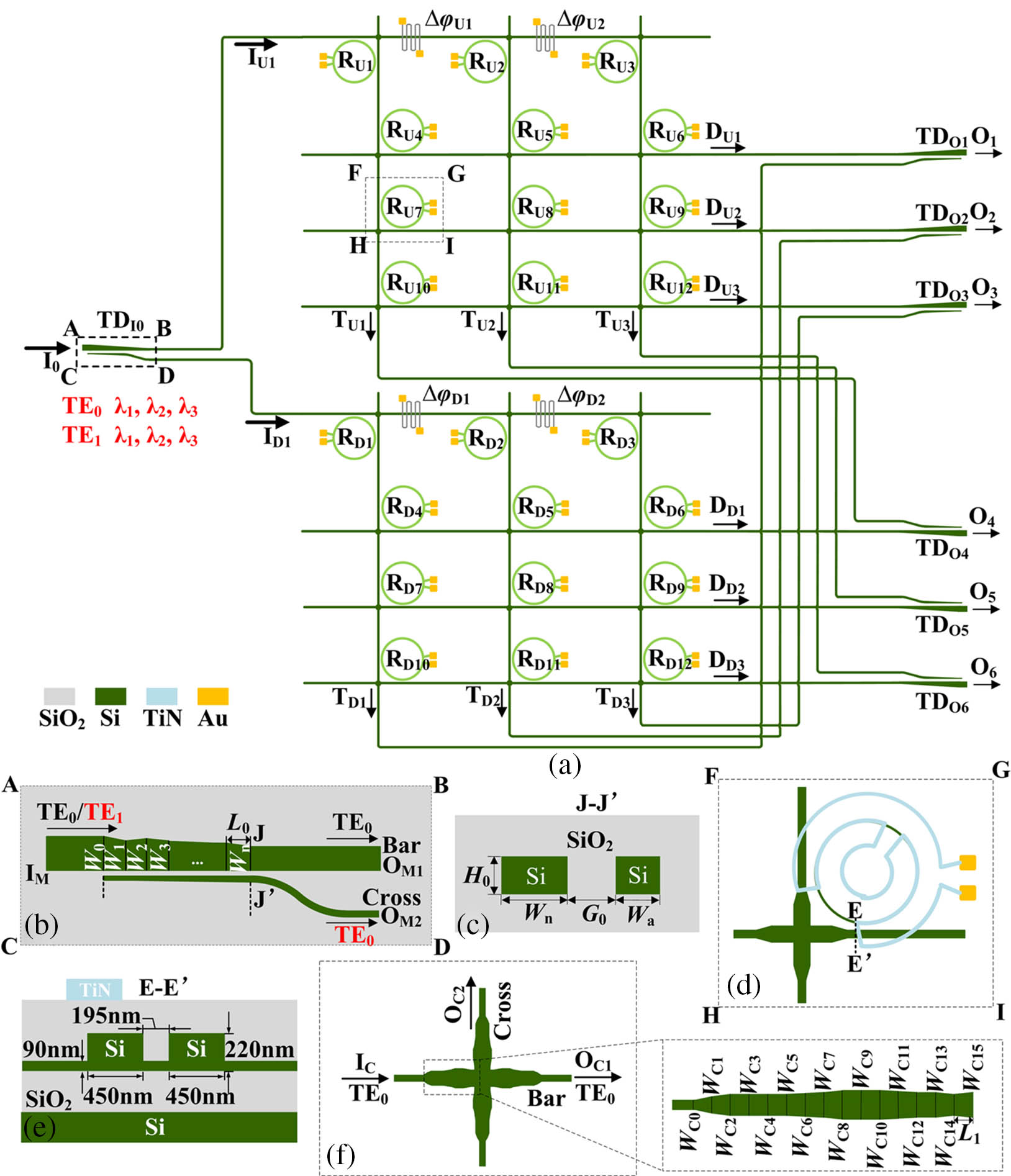
    Fig. 1. (a) Schematic diagram of the flexible-grid 1 × (2 × 3) MWSS; (b) detailed drawing and (c) cross-sectional view of the proposed two-mode (de)multiplexer; (d) schematic diagram and (e) cross-sectional view of the mentioned silicon MRR; (f) structure of the proposed crossing waveguide.
    Working principle of forming the tunable BW.
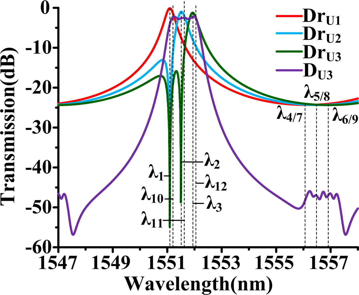
    Fig. 2. Working principle of forming the tunable BW.
    Simulated transmission spectra of the designed silicon-based flexible-grid 1 × (2 × 3) MWSS in the typical states.
    Fig. 3. Simulated transmission spectra of the designed silicon-based flexible-grid 1 × (2 × 3) MWSS in the typical states.
    Simulated maximum IL, worst CT, and minimum ER of (a) the designed flexible-grid 1 × (2 × 3) MWSS or (b) the designed flexible-grid 1 × (2 × 3) MWSS cascaded with a mode multiplexer and six mode demultiplexers changing with ΔW.
    Fig. 4. Simulated maximum IL, worst CT, and minimum ER of (a) the designed flexible-grid 1 × (2 × 3) MWSS or (b) the designed flexible-grid 1 × (2 × 3) MWSS cascaded with a mode multiplexer and six mode demultiplexers changing with ΔW.
    Microscope image of the fabricated module.
    Fig. 5. Microscope image of the fabricated module.
    Measured transmission spectra of the fabricated module.
    Fig. 6. Measured transmission spectra of the fabricated module.
    Measured dynamic response of the fabricated device.
    Fig. 7. Measured dynamic response of the fabricated device.
    StatesOutput Ports
    O1O2O3O4O5O6
    1TE0-λ2TE0-λ3TE0-λ1TE1-λ2TE1-λ3TE1-λ1
    2TE0-λ3TE0-λ2TE0-λ1TE1-λ3TE1-λ2TE1-λ1
    3TE1-λ3TE0-λ2TE0-λ1TE0-λ3TE1-λ2TE1-λ1
    4TE0-λ2TE1-λ3TE1-λ1TE1-λ2TE0-λ3TE0-λ1
    5TE1-λ3TE0-λ2TE1-λ1TE1-λ2TE0-λ3TE0-λ1
    6TE1-λ2TE0-λ3TE1-λ1TE1-λ3TE0-λ2TE0-λ1
    7TE0-λ1TE1-λ2TE1-λ3TE1-λ1TE0-λ2TE0-λ3
    8TE1-λ1TE1-λ2TE1-λ3TE0-λ1TE0-λ2TE0-λ3
    9TE0-λ1λ3TE1-λ1λ3
    10TE0-λ2, λ3TE0-λ1TE1-λ2, λ3TE1-λ1
    11TE0-λ1, λ3TE0-λ2TE1-λ1, λ3TE1-λ2
    12TE0-λ1, λ2TE0-λ3TE1-λ1, λ2TE1-λ3
    13TE0-λ3TE0-λ1, λ2TE1-λ3TE1-λ1, λ2
    14TE0-λ2TE0-λ1, λ3TE1-λ2TE1-λ1, λ3
    15TE0-λ1TE0-λ2, λ3TE1-λ1TE1-λ2, λ3
    16TE0-λ1λ3TE1-λ1λ3
    Table 1. Typical States of the Presented Flexible-grid 1 × (2 × 3) MWSS in the Worst Situation
    SymbolValue/µmSymbolValue/µmSymbolValue/µm
    W00.85W10.85W20.74
    W30.75W40.78W50.71
    W60.62W70.62W80.58
    W90.59W100.45
    Table 2. Optimized Segments’ Widths for the Bus Waveguide in the Coupling Region
    SymbolValue/µmSymbolValue/µmSymbolValue/µm
    WC00.45WC10.70WC20.86
    WC30.88WC40.90WC50.90
    WC60.96WC71.04WC81.16
    WC91.16WC101.16WC111.10
    WC121.06WC131.06WC140.90
    WC151.00
    Table 3. Optimized Segments’ Widths for the Taper in the Crossing Waveguide
    Dejun Kong, Hao Lu, Pengjun Wang, Qiang Fu, Shixun Dai, Weiwei Chen, Yuefeng Wang, Bohao Zhang, Lingxiao Ma, Jun Li, Tingge Dai, Jianyi Yang. Experimental demonstration of a flexible-grid 1 × (2 × 3) mode- and wavelength-selective switch using silicon microring resonators and counter-tapered couplers[J]. Chinese Optics Letters, 2024, 22(1): 011301
    Download Citation