• Chinese Optics Letters
  • Vol. 15, Issue 10, 101203 (2017)
Meng Zheng, Ke Liu, Lihui Liu, and Yanqiu Li*
Author Affiliations
  • Key Laboratory of Photoelectronic Imaging Technology and Systems, Ministry of Education of China, School of Optoelectronics, Beijing Institute of Technology, Beijing 100081, China
  • show less
    DOI: 10.3788/COL201715.101203 Cite this Article Set citation alerts
    Meng Zheng, Ke Liu, Lihui Liu, Yanqiu Li. Design of a grating by a joint optimization method for a phase-shifting point diffraction interferometer[J]. Chinese Optics Letters, 2017, 15(10): 101203 Copy Citation Text show less

    Abstract

    A grating is an important element of a phase-shifting point diffraction interferometer, and the grating constant and duty cycle have a great impact on the interferometer, so the design of a grating becomes significant. In order to measure the projection objective with a numerical aperture of 0.2, we present a joint optimization method of a pinhole and grating based on scalar diffraction and the finite difference time domain method. The grating constant and the film thickness are selected, and the duty cycle of the grating is optimized. The results show that in the grating processing the material chromium is adopted, the thickness is 200 nm, and the grating constant is 15 μm. When the duty cycle is 55%, the interference fringe contrast is the greatest. The feasibility of the design result is further verified by experiment.

    A phase-shifting point diffraction interferometer (PS/PDI) is a device with the greatest accuracy so far that is applied to the detection of wavefront aberration of the projection objective[13]. Having no need of any reference element, the PS/PDI produces a reference spherical wave with the help of pinhole diffraction, which is why the measuring result is not restricted by the machining precision of a standard lens and the detection accuracy is very high. Many PDI studies, either theoretical or experimental, have been performed recently[411]. A PS on-axis PDI has also been investigated, which has a low requirement on the space-bandwidth of the CCD camera[12]. A transmission grating[1316] is an important element as well, performing the function of beam splitting, and the grating constant and duty cycle usually exert a great impact on the interferometer. A number of researchers abroad to the PS/PDI have invariably indicated that the duty cycle of the grating needs to be decided based on an optimized calculation and the result depends on the projection objective and the pinhole diameter of the diffraction plate of the image space, but the calculation methods were not given[1719].

    Figure 1 shows the schematic of the PS/PDI established by our laboratory[20,21]. As shown in Fig. 1, the object pinhole spatially filters the light from the source into a perfect spherical wave. The binary diffraction grating splits the beam from the object pinhole into multiple diffraction orders that illuminate the test optics. The PS/PDI mask, which is located at the image plane of the optical system under test, is aligned such that the 0th order illuminates the reference pinhole and the +1st order falls on the center of the test window. All the other diffraction orders are blocked by the mask. The 0th-order wave is spatially filtered by the pinhole and generates a spherical reference wave. The +1st order, which passes through the relatively large test window and remains undisturbed, contains the aberration imparted by the test optics. The test and reference beams propagate to the mixing plane, where they generate an interference pattern recorded by CCD. By translating the grating perpendicular to the grating line direction, PS interferometry can be achieved. Here, the role of the transmission grating is to split the beam.

    Schematic view of the PS/PDI.

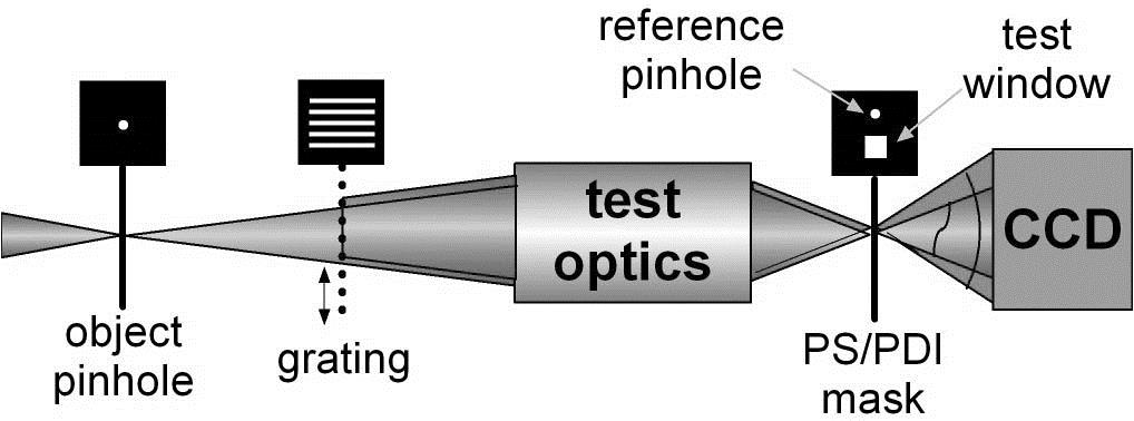
    Figure 1.Schematic view of the PS/PDI.

    In this Letter, the grating is designed in order to measure the projection objective with a numerical aperture (NA)of 0.2. Through joint optimization method (JOM) of a pinhole and grating based on scalar diffraction and the finite difference time domain (FDTD), the grating constant and the film thickness are determined, and the duty cycle is optimized. The optimization method is suitable for measuring projection objectives with an arbitrary NA.

    There are many factors that influence the interference fringe contrast, for example, the NA of the measured projection objective, the grating constant, the grating film coating material, the grating film thickness, the grating duty cycle, and the reference pinhole diameter. In order to measure the projection objective with NA 0.2, the present work is distributed into three main parts: the grating constant, grating film material, and thickness were determined. The theoretical approach and proper equations to retrieve the duty cycle of the grating, in which the grating constant, grating film material and thickness, and reference pinhole diameter are considered. An experimental is carried out and the results show the rationality.

    In the design of a grating for a PS/PDI, the grating constants usually are 20[17], 18[18], or 15 μm[19]. In this Letter, the grating constant is determined to be 15 μm.

    In the visible band (λ=632.8nm), the film coating materials of the grating usually use chromium (Cr) film. The calculated transmittance curve of Cr by FDTD is shown in Fig. 2, in which the vertical axis indicates the normalized optical power. From the transmittance curve, we can see that when the thickness of the Cr film is 200 nm, the transmittance is 2.44×10⁶, so the opaque part of the grating is able to stop light enough. Therefore, the thickness of the grating Cr film is determined to be 200 nm.

    Cr film transmittance versus thickness.

    Figure 2.Cr film transmittance versus thickness.

    The JOM of the duty cycle of the grating is determined as follows. First, the diffraction efficiency of the 0th order and the +1st order of the grating is calculated according to the distant field Fraunhofer approximation in which the grating constant, grating film material, and thickness are considered. Then, the diffraction efficiency after the 0th-order light goes through the reference pinhole will be calculated by means of FDTD. Finally, the fringe contrast and the optimized grating duty cycle are obtained.

    The single-slit diffraction characteristics under spherical wave illumination are studied, and then the analysis is extended to grating diffraction. It is assumed that the point light source is located in the vertical surface of the slit center with a width of 2a, as is shown in Fig. 3.

    Single-slit diffraction.

    Figure 3.Single-slit diffraction.

    According to Rayleigh–Sommerfeld diffraction, the integral formula is U(p)=AjλΣexp[jk(r0+r)]r0rKds.

    In Eq. (1), A refers to a constant, k=2π/λ is the wavenumber, and K is the inclination factor K=cos(n,r).

    According to the Rayleigh–Sommerfeld diffraction formula, the complex amplitude distribution of point p on the image surface can be gotten from the axis point p0, as follows: U(p)=Ajλr0lexp[jk(r0+l)]ΣKexp(jkβ)ds.

    In Eq. (2), l refers to the spacing from the slit to the image surface and exp(ikβ) is the phase difference between point p0 and point p in the image plane. Without regard to sub-wave diffraction, the amplitude when the light emitted from the light source transmits to point p0 is u0=Ar0+lexp[jk(r0+l)].

    Letting 1/f=(1/r0)+(1/l), then f=r0l/(r0+l), then Eq. (3) can be expressed as u0=fAr0lexp[jk(r0+l)].

    Substituting Eq. (4) into Eq. (2), we get U(p)=u0jλfΣKexp(jkβ)ds.

    For p0, K=cos(n,d)=cos0=1, and Eq. (5) can be expressed as U(p)=u0jλfΣexp(jkβ)ds.

    In Eq. (6), β is the optical path difference between p0 and p. Expanding β and ignoring the higher-order items, we get U(p)=u0jλfΣexp{jk2l[(xζ)2+(yη)2]}ds.

    Equation (7) can be organized as U(p)=u0ljf(1λlaaexp[jk2l(xξ)2]dξ)(1λlbbexp[jk2l(yη)2]dη).

    When one side of the matrix aperture b, the matrix aperture becomes a slit. So, Eq. (8) can be expressed as U(p)=u0ljf2λl(1+j)aaexp[jk2l(xζ)2]dζ.

    Making use of the Fraunhofer approximation[22], removing the higher-order integral, letting fl, Eq. (9) is described by U(p)=u0j2λl(1+j)exp(jkx22l)aaexp(jkxζl)dζ.

    Equation (10) is the single-slit diffraction formula under point light source illumination.

    The Fraunhofer approximation of multiple-slit diffraction is U(p)=Asin(Nδ/2)sin(δ/2)exp[j(N1)δ2].

    In Eq. (11), A refers to the amplitude of incident light, δ=(2π/λ)dsinθ is the optical path difference, N is the number of slits, d is the grating constant, and θ is the diffraction angle. From Eqs. (10) and (11), we get the multiple-slit diffraction formula U(p)=u0j2λl(1+j)exp(jkx22l)aaexp(jkxζl)dζ×sin(Nδ/2)sin(δ/2)exp[j(N1)δ2].

    Therefore, the intensity distribution of the grating diffraction is I(p)=|U(p)|2=u02λl(sin(Nδ/2)sin(δ/2))2|aaexp(jkxζl)dζ|2.

    When δ=2πdsinθ/λ=2mπ, the interference factor has a maximum value; in other words, I(p) has a maximum value so that the diffraction order is realized. The expression of the maximum value is Im=I01d2(sinNmπNsinmπ)2|aaexp(jkxζl)dζ|2.

    Considering the transmittance of the grating line, if expressed in the pupil function F(ζ)[23], and when the intensity has a maximum value we get Im=I01d2|aaF(ζ)exp(j2mπζd)dζ|2.

    In PS/PDI, a rectangular linear grating is used whose structure is shown in Fig. 4, and the pupil function of a linear grating is F(ζ)={1ζ[a,a]exp[jkz(δ+jβ)]ζ(a,da].

    Structure of the rectangular linear grating.

    Figure 4.Structure of the rectangular linear grating.

    In Eq. (16), 1δ and β refers to the real and imaginary parts of the reflecting index of the metal material used for the grating line and z refers to the thickness of the material. When Eq. (16) is substituted into Eq. (15), it is expressed as Im=I01d2|aaexp(j2mπζd)dζ+adaexp[jkz(δ+jβ)]exp(j2mπζd)dζ|2.

    From Eq. (17), we can get the grating diffraction intensity of different orders.

    The grating parameter of the PS/PDI is d=15μm, the material of the grating ruling is Cr. According to processing conditions, the thickness of the grating film is 200 nm and the refraction index of Cr is 2.65+3i. Under the condition of a different duty cycle, the diffraction efficiency of the 0th order and +1st order is shown Fig. 5.

    (Color online) Curve of the grating diffraction efficiency.

    Figure 5.(Color online) Curve of the grating diffraction efficiency.

    We can see that with the increase of duty cycle (in this paper, the duty cycle of the grating refers to the ratio of the transparent part and the grating constant), the diffraction efficiency of the 0th order increases and that of +1st order first increases and then decreases.

    The 0th-order light of the grating diffraction needs to go through the reference pinhole in the PS/PDI mask, so the transmittance of the different diameter reference pinhole in the PS/PDI mask is calculated with the method of FDTD, which is shown in Fig. 6. The light transmittance increases with the increase of the diameter of the pinhole. For the projection objective with an NA of 0.2, the pinhole diameter of PS/PDI mask is determined to be 1.5 μm[24] and therefore the intensity transmittance is 0.3566.

    Curve of the pinhole transmittance.

    Figure 6.Curve of the pinhole transmittance.

    When 0th-order light interferes with +1st-order light, the interference fringe contrast is K=2I0I1I0+I1.

    The curve of the interference fringe contrast is shown in Fig. 7.

    Curve of the interference fringe contrast.

    Figure 7.Curve of the interference fringe contrast.

    From Fig. 7, we can see that when the duty cycle of the grating is 0.55, the curve has a peak; that is, the contrast of interference fringe is the biggest.The interference fringe contrast decreases rapidly with the increase in duty cycle.

    The experiment is carried out and the apparatus is shown is Fig. 8. The projection objective is a 20X-demagnification Schwarzschild objective whose NA is 0.2, and the reference pinhole diameter is 1.5 μm, wherein the grating structure adopts the above design method. Table 1 is the grating structure parameters.

    Grating Constant (μm)Duty CycleFilm Thickness (nm)Film Coating Materials
    1555%200Cr

    Table 1. Grating Design Parameters for PS/PDI

    PS/PDI structure of the homemade grating and interferograms. (a) A grabbed interferogram, (b) an interferogram of the removed background, (c) the homemade grating adopts the design method in this Letter, (d) an enlarged view of (b), and (e) a Zernike coefficient diagram of the measurement results.

    Figure 8.PS/PDI structure of the homemade grating and interferograms. (a) A grabbed interferogram, (b) an interferogram of the removed background, (c) the homemade grating adopts the design method in this Letter, (d) an enlarged view of (b), and (e) a Zernike coefficient diagram of the measurement results.

    The PS/PDI structure of the homemade grating and interferograms are shown in Fig. 8.The interferogram has a good intensity contrast and clear fringe. From the interferogram of the removed background [Fig. 8(b)], we can calculate that the interference fringe contrast is 90%.

    The homemade grating adopts the design method in this Letter is shown in the Fig. 8(c). We then use PS/PDI to measure the projection objective of NA 0.2. Using the phase-shift method and acquiring five interferograms of the removed background, the projection objective wavefront aberration can be measured. Figure 8(e) is the Zernike coefficient diagram of the measurement results. According to the final calculation, the peak to valley (PV) value of the measured projection objective is 0.6140λ and the root-mean-square (RMS) value is 0.07109λ. Such a result is consistent with the measurement results of commercial equipment Zygo (PV=0.6096λ, RMS=0.07206λ).

    A diffraction grating is an important element of a PS/PDI that performs important functions. We clarify the method of designing the grating for a PS/PDI, determine the grating constant, and present the principles for the selection of the film thickness. We also optimize and calculate the duty cycle of the grating by JOM of the pinhole and grating based on scalar diffraction and FDTD so that the interference fringe with the greatest intensity contrast is obtained. This Letter guides the processing of the grating with design result, and the experiment shows that interference fringes with excellent contrast can be obtained and the measuring result is true. The design method in this Letter is suitable for projection objective measurements with arbitrary NA.

    References

    [1] H. Medecki. Phase-shifting point diffraction interferometer(1998).

    [2] H. Medecki, E. Tejnil, K. A. Goldberg. Opt. Lett., 21, 1526(1996).

    [3] Y. Zhu, K. Sugisaki, M. Okada. Proc. SPIE, 5752, 1192(2005).

    [4] V. Akondi, A. R. Jewel, B. Vohnsen. Opt. Lett., 39, 1641(2014).

    [5] Y. Du, G. Feng, H. Li. Opt. Lett., 37, 19(2012).

    [6] W. Zhu, L. Chen, C. Gu. Appl. Opt., 54, 20(2015).

    [7] K. Yamamoto, T. Matsuo. Appl. Opt., 54, 7895(2015).

    [8] J. C. Aguilar, L. R. Berriel-Valdos, J. F. Aguilar. Opt. Eng., 52, 104103(2013).

    [9] T. Matsuura, K. Udaka. Nucl. Instrum. Methods Phys. Res. A, 616(2010).

    [10] G. Liu, B. Lu, H. Sun, B. Liu, F. Chen, Z. Zhuang. Chin. Opt. Lett., 14, 071202(2016).

    [11] Y. Xu, Y. Wang, Y. Ji. Chin. Opt. Lett., 13, S21001(2015).

    [12] P. Gao, I. Harder, V. Nercissian. Opt. Lett., 35, 5(2010).

    [13] W. Shang, T. Zhu, G. Xiong. Acta Phys. Sin., 60, 034216(2011).

    [14] J. Ma, C. Xie, T. Ye. Acta Phys. Sin., 59, 2564(2010).

    [15] W. Zhu, Y. Wu, M. Chen, N. Wang, R. Tai, H. Xu. Acta Opt. Sin., 28, 1225(2008).

    [16] S. Yang, B. Chen, B. Lin. Chin. Opt. Lett., 13, 120501(2015).

    [17] P. Naulleau, K. A. Goldberg, E. Tejnil. Phase-shifting point diffraction interferometer grating designs(2001).

    [18] K. A. Goldberg. Phase-shifting point diffraction interferometer mask designs(2001).

    [19] K. Sugisaki, Y. Zhu, Y. Gomei. Proc. SPIE, 4146, 47(2000).

    [20] K. Liu, Y. Li, H. Wang. Rev. Sci. Instrum., 82, 033105(2011).

    [21] K. Liu, Y. Li. Acta Opt. Sin., 30, 2923(2010).

    [22] T. Liang. Physical Optics(2011).

    [23] W. Shuang, J. Yang, Y. Zhao. Acta Phys. Sin., 60, 1358(2011).

    [24] M. Zheng, Y. Li, K. Li. Laser Optoelectron. Prog., 50, 031201(2012).

    Meng Zheng, Ke Liu, Lihui Liu, Yanqiu Li. Design of a grating by a joint optimization method for a phase-shifting point diffraction interferometer[J]. Chinese Optics Letters, 2017, 15(10): 101203
    Download Citation