• Chinese Optics Letters
  • Vol. 21, Issue 1, 011403 (2023)
Zhenxing Sun1, Yaguang Wang1, Rulei Xiao1、*, Leilei Wang1, Yangyang Gong1, Yi-Jen Chiu2, and Xiangfei Chen1、**
Author Affiliations
  • 1Key Laboratory of Intelligent Optical Sensing and Manipulation of the Ministry of Education & Nanjing University-Tongding Joint Lab for Large-scale Photonic Integrated Circuits & National Laboratory of Solid-State Microstructures & College of Engineering and Applied Science & Institute of Optical Communication Engineering, Nanjing University, Nanjing 210093, China
  • 2Department of Photonics and Institute of Electro-Optical Engineering, Taiwan Sun Yat-sen University, Kaohsiung 80424, China
  • show less
    DOI: 10.3788/COL202321.011403 Cite this Article Set citation alerts
    Zhenxing Sun, Yaguang Wang, Rulei Xiao, Leilei Wang, Yangyang Gong, Yi-Jen Chiu, Xiangfei Chen. Directly modulated 25 Gbaud/s tunable in-series DFB laser array for WDM systems[J]. Chinese Optics Letters, 2023, 21(1): 011403 Copy Citation Text show less
    (a) Schematic of the proposed structure of one laser unit and (b) calculated normalized optical intensity of the lasing mode along the cavity of one laser unit. (SS, side section; GS, gain section; SCH-MQW, separate confinement hetero-structure-multi-quantum well; BG, Bragg grating; BCB, benzocyclobutene; WG, waveguide).
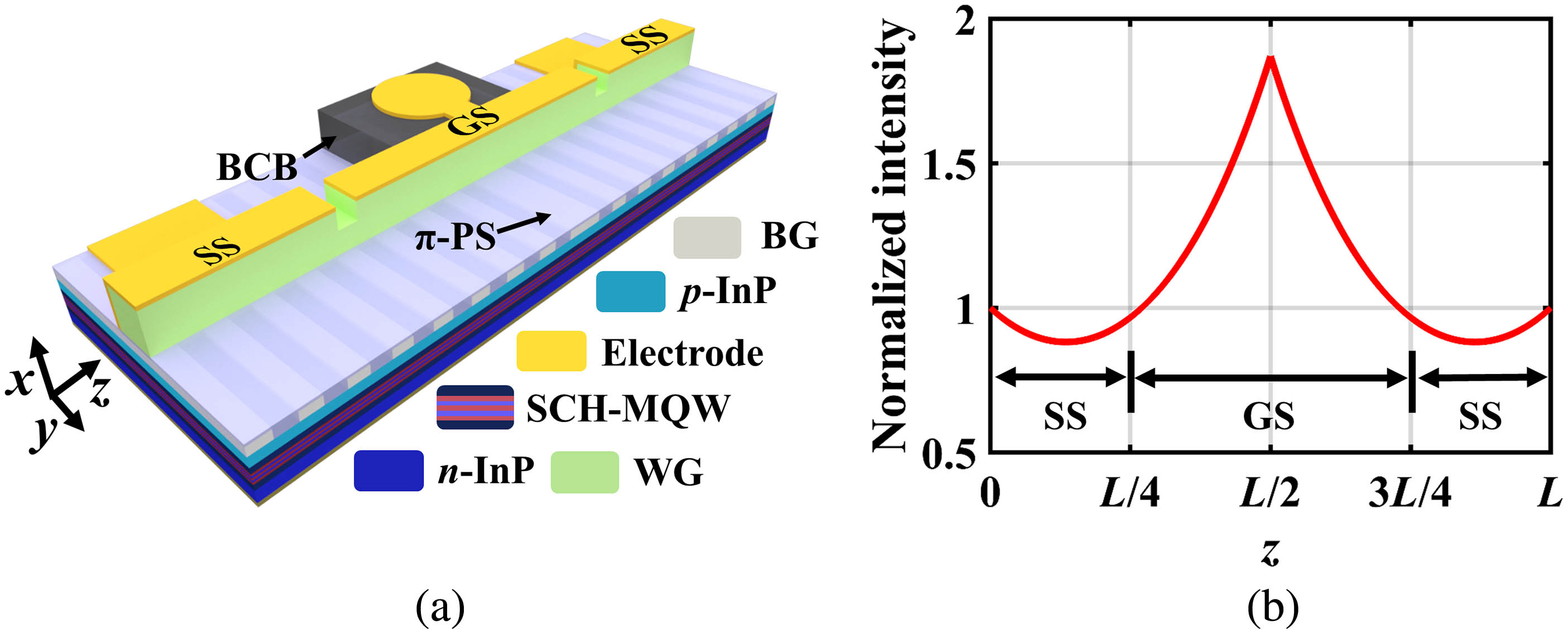
    Fig. 1. (a) Schematic of the proposed structure of one laser unit and (b) calculated normalized optical intensity of the lasing mode along the cavity of one laser unit. (SS, side section; GS, gain section; SCH-MQW, separate confinement hetero-structure-multi-quantum well; BG, Bragg grating; BCB, benzocyclobutene; WG, waveguide).
    (a) Schematic of the grating designed by the REC technique and (b) sampling periods of the four in-series lasers (π-EPS: equivalent π phase shift).
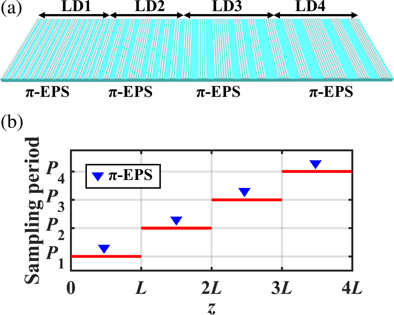
    Fig. 2. (a) Schematic of the grating designed by the REC technique and (b) sampling periods of the four in-series lasers (π-EPS: equivalent π phase shift).
    Picture of the DMTL chip under the microscope (SOA, semiconductor optical amplifier; LD, laser diode).
    Fig. 3. Picture of the DMTL chip under the microscope (SOA, semiconductor optical amplifier; LD, laser diode).
    (a) Microscopic top view of the DMTL COS and (b) superimposed optical spectra of all four lasers (DMTL, directly-modulated tunable in-series laser array; GCPW, ground coplanar waveguide; COS, chip on submount).
    Fig. 4. (a) Microscopic top view of the DMTL COS and (b) superimposed optical spectra of all four lasers (DMTL, directly-modulated tunable in-series laser array; GCPW, ground coplanar waveguide; COS, chip on submount).
    (a) Optical spectra of LD1 as a function of IGS when ISOA and ISS are both fixed at 30 mA and (b) optical spectra of LD1 as a function of ISS when ISOA and IGS are fixed at 30 and 70 mA, respectively (ISOA, current injected into the semiconductor optical amplifier; IGS, current injected into the gain section; ISS, current injected into the side section).
    Fig. 5. (a) Optical spectra of LD1 as a function of IGS when ISOA and ISS are both fixed at 30 mA and (b) optical spectra of LD1 as a function of ISS when ISOA and IGS are fixed at 30 and 70 mA, respectively (ISOA, current injected into the semiconductor optical amplifier; IGS, current injected into the gain section; ISS, current injected into the side section).
    (a) Power-current-voltage curve of LD1 with ISOA of 10 mA and (b) laser output power as a function of the ISOA for the four lasers with the IGS and ISS set at 80 and 30 mA (ISOA, current injected into the semiconductor optical amplifier; IGS, current injected into the gain section; ISS, current injected into the side section).
    Fig. 6. (a) Power-current-voltage curve of LD1 with ISOA of 10 mA and (b) laser output power as a function of the ISOA for the four lasers with the IGS and ISS set at 80 and 30 mA (ISOA, current injected into the semiconductor optical amplifier; IGS, current injected into the gain section; ISS, current injected into the side section).
    (a) Lasing spectra of the tuned 12 channels and (b) tuned temperature of the TEC (left) and SMSRs of all the 12 channels (right) (SMSR, side mode suppression ratio).
    Fig. 7. (a) Lasing spectra of the tuned 12 channels and (b) tuned temperature of the TEC (left) and SMSRs of all the 12 channels (right) (SMSR, side mode suppression ratio).
    (a) EO response of LD1 when IGS is varied from 40 to 100 mA and (b) EO response of all the four lasers when IGS is 100 mA (GS, gain section; IGS, current injected into the GS).
    Fig. 8. (a) EO response of LD1 when IGS is varied from 40 to 100 mA and (b) EO response of all the four lasers when IGS is 100 mA (GS, gain section; IGS, current injected into the GS).
    Measured back-to-back 25 Gb/s NRZ optical eye diagrams and 25 Gb/s NRZ eye diagrams after 10 km transmission for all 12 channels (Ch., channel; BtB, back-to-back).
    Fig. 9. Measured back-to-back 25 Gb/s NRZ optical eye diagrams and 25 Gb/s NRZ eye diagrams after 10 km transmission for all 12 channels (Ch., channel; BtB, back-to-back).
    (a) Electrical eye diagram of the 50 Gb/s PAM4 signal after the electrical amplifier and (b) measured 50 Gb/s PAM4 optical eye diagram for channel 10.
    Fig. 10. (a) Electrical eye diagram of the 50 Gb/s PAM4 signal after the electrical amplifier and (b) measured 50 Gb/s PAM4 optical eye diagram for channel 10.
    Zhenxing Sun, Yaguang Wang, Rulei Xiao, Leilei Wang, Yangyang Gong, Yi-Jen Chiu, Xiangfei Chen. Directly modulated 25 Gbaud/s tunable in-series DFB laser array for WDM systems[J]. Chinese Optics Letters, 2023, 21(1): 011403
    Download Citation