• Laser & Optoelectronics Progress
  • Vol. 56, Issue 7, 070501 (2019)
Wei Wang*, Jianguang Wu, Xutao Mo, and Xianshan Huang
Author Affiliations
  • School of Mathematics and Physics, Anhui University of Technology, Maanshan, Anhui 243032, China
  • show less
    DOI: 10.3788/LOP56.070501 Cite this Article Set citation alerts
    Wei Wang, Jianguang Wu, Xutao Mo, Xianshan Huang. Binary Annular Phase Plate Used to Generate Hollow Focal Field[J]. Laser & Optoelectronics Progress, 2019, 56(7): 070501 Copy Citation Text show less
    Schematic for calculation of focal field
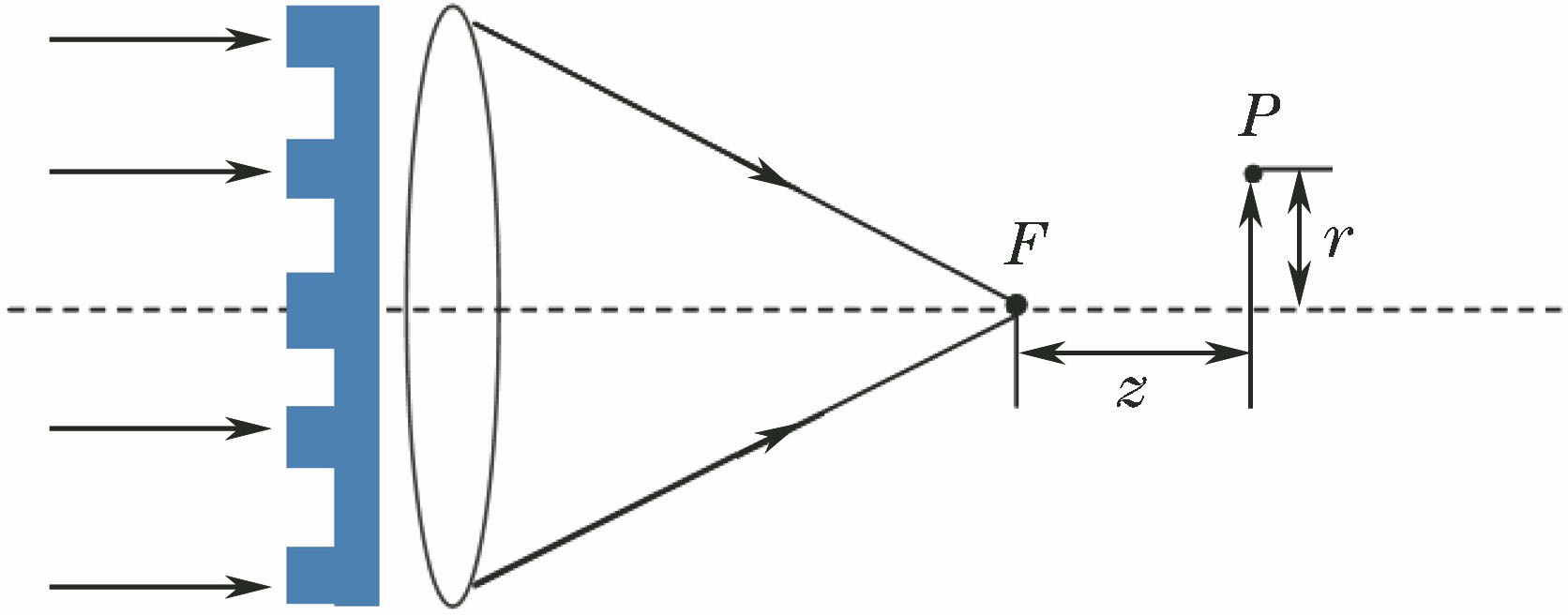
    Fig. 1. Schematic for calculation of focal field
    Light intensity distribution in focal plane for two-ring structure
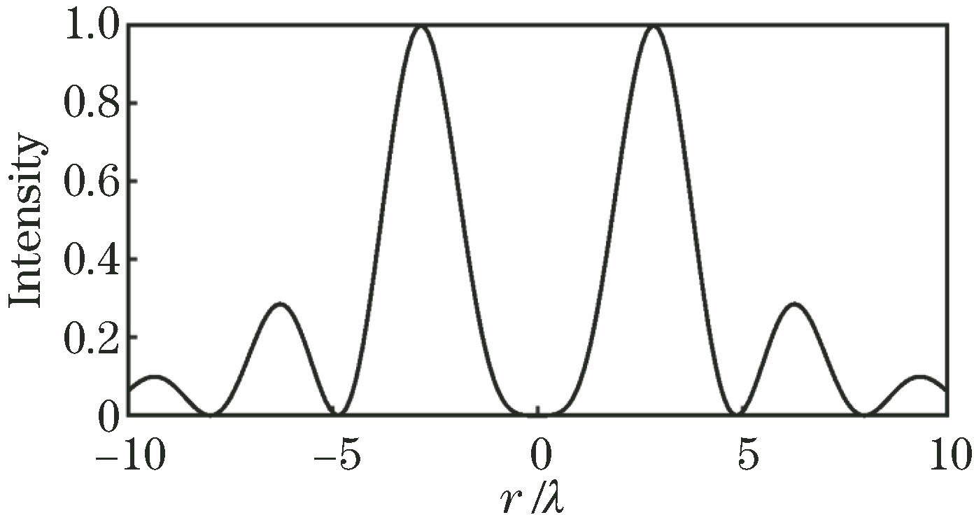
    Fig. 2. Light intensity distribution in focal plane for two-ring structure
    Light intensity distributions in focal plane for three-ring structure. (a) R=5.65λ; (b) R=2.85λ
    Fig. 3. Light intensity distributions in focal plane for three-ring structure. (a) R=5.65λ; (b) R=2.85λ
    Light intensity distributions in focal plane for different ring structures. (a) 2-ring; (b) 3-ring; (c) 4-ring; (d) 5-ring; (e) 6-ring
    Fig. 4. Light intensity distributions in focal plane for different ring structures. (a) 2-ring; (b) 3-ring; (c) 4-ring; (d) 5-ring; (e) 6-ring
    R, M, S in focal plane versus NA. (a) R value for 4-ring; (b) R value for 5-ring; (c) S and M values for 4-ring; (d) S and M values for 5-ring
    Fig. 5. R, M, S in focal plane versus NA. (a) R value for 4-ring; (b) R value for 5-ring; (c) S and M values for 4-ring; (d) S and M values for 5-ring
    Light intensity distributions in axial direction for different ring structures. (a) 2-ring; (b) 3-ring; (c) 4-ring; (d) 5-ring; (e) 6-ring
    Fig. 6. Light intensity distributions in axial direction for different ring structures. (a) 2-ring; (b) 3-ring; (c) 4-ring; (d) 5-ring; (e) 6-ring
    R, M, S in axial direction versus NA. (a) R value for 4-ring; (b) R value for 5-ring; (c) S and M values for 4-ring; (d) S and M values for 5-ring
    Fig. 7. R, M, S in axial direction versus NA. (a) R value for 4-ring; (b) R value for 5-ring; (c) S and M values for 4-ring; (d) S and M values for 5-ring
    Number of ringsRelation among normalized ring radii
    22ρ12-1=0
    32(ρ12-ρ22)+1=0
    42(ρ12-ρ22+ρ32)-1=0
    52(ρ12-ρ22+ρ32-ρ42)+1=0
    62(ρ12-ρ22+ρ32-ρ42+ρ52)-1=0
    Table 1. Radius of each ring when generating hollow focal field
    ρ1ρ2R /λSM
    0.350.7895.6490.0650.208
    0.690.9882.920.0980.288
    0.010.7072.8450.1080.287
    Table 2. Optimized three-ring structure
    ρ1ρ2ρ3R /λSM
    0.60.730.822.880.070.12
    0.580.690.802.840.070.12
    0.570.700.8162.880.0650.12
    0.550.650.7872.840.070.11
    Table 3. Optimized four-ring structure
    ρ1ρ2ρ3ρ4R /λSM
    0.360.680.720.8285.520.050.15
    0.540.640.760.983.010.0600.11
    0.550.660.770.983.010.0590.10
    0.560.670.780.982.910.0640.11
    Table 4. Optimized five-ring structure
    ρ1ρ2ρ3ρ4ρ5R /λSM
    0.400.410.600.730.832.910.0660.10
    0.390.400.580.690.802.810.0660.10
    0.490.500.600.710.812.910.0710.11
    0.500.510.610.730.822.910.0710.11
    Table 5. Optimized six-ring structure
    Number of ringsρ1ρ2ρ3ρ4ρ5R /λSM
    20.70737.0460.5250.088
    30.010.70737.0360.5250.088
    40.590.650.75835.0340.3920.153
    50.560.620.730.98138.0370.3320.174
    60.50.540.690.730.77435.2840.3760.079
    Table 6. Ring radii and R, S, M values corresponding to Fig. 6
    Wei Wang, Jianguang Wu, Xutao Mo, Xianshan Huang. Binary Annular Phase Plate Used to Generate Hollow Focal Field[J]. Laser & Optoelectronics Progress, 2019, 56(7): 070501
    Download Citation