
Min JIN, Xudong BAI, Su ZHAO, Rulin ZHANG, Yuqi CHEN, Lina ZHOU. Mechanical Property of SnSe Single Crystal Prepared via Vertical Bridgman Method [J]. Journal of Inorganic Materials, 2021, 36(3): 313
- Journal of Inorganic Materials
- Vol. 36, Issue 3, 313 (2021)
Abstract
During the past decades, thermoelectric (TE) material has attracted much attention as it can transfer heat directly into electricity and vice versa[
However, it should be pointed out that most of the present researches about SnSe single crystals are focused on its TE properties, other equally important information such as the mechanical performances are serious in shortage. It is imaginable that if SnSe single crystal is processed for TE module fabrication and then put into service, the material will inevitably experience complicated shocks and stress. Under this condition, the mechanical properties of SnSe single crystal would be essential to estimate whether it is proper for commercial application or not. According to publications, most of the work related to mechanical properties rely on SnSe polycrystalline, which usually prepared through hot pressing (HP) or spark plasma sintering (SPS) techniques[
1 Experimental
1.1 SnSe crystal growth
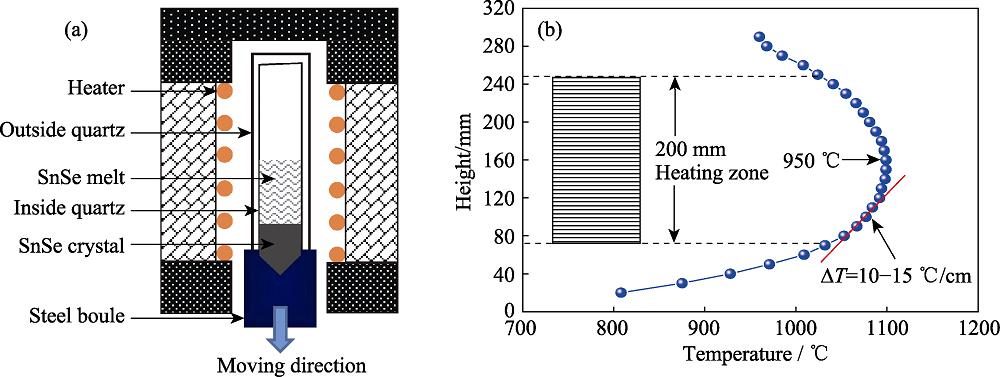
99.999% purity Sn and Se elements were used as raw materials for polycrystalline synthesis. They were weighted according to the standard stoichiometric ratio and the total weight was 98.6 g. In order to prevent SnSe from oxidation once the utilized quartz ampoule was crack, an outside ampoule was simultaneously employed and they were all sealed with ~10-2 Pa vacuum. Sn and Se reacted in a 900 ℃ rocking furnace which worked at a 20-25 r/min speed to enhance SnSe synthesis homogeneously. After that, SnSe single crystal growth was carried out in a homemade vertical Bridgman furnace. Fig. 1(a) shows the schematic diagram of the furnace, and the sealed quartz ampoule with SnSe polycrystalline was placed into the chamber and supported by a steel pillar. Fig. 1(b) exhibits the temperature profile of the furnace along vertical direction. The heating zone was about 200 mm in height, and the highest temperature was designed about 950 ℃. After SnSe polycrystalline was totally melted, SnSe crystal growth was executed through the lowing system at a 1.0 mm/h rate, and the temperature gradient for crystallization was 10-15 ℃/cm. After all solution was exhausted, the furnace was cooled to room temperature naturally.
![]()
Figure 1.Schematic diagram of vertical Bridgman furnace (a) and temperature profile along vertical direction (b)
1.2 Characterization
The phase structure and crystal direction of SnSe crystal was analyzed by X-ray diffraction (Bruker D8, Germany) using Cu Kα radiation (λ=0.15406 nm) at room temperature. The X-ray rocking curve of SnSe crystal was detected by D8 Discover (Bruker AXS, Germany). The configuration of crystal surface was examined by Energy Dispersive Spectrometer (Oxford Instruments, Britain), and the composition was tested by an EDAX system (Gemsis Software V 4.61). Vickers’ microhardness equipment (Wilson-Wlpert Tukon 2100B) with a diamond square pyramid indentor was employed to induce indentations by keeping the indentor to the crystal surface for 10 s in all cases. The distance of indentations were enough far from each other so that the surface effects could be avoided. As for friction property evaluation, the nanoscratch tests were carried out via a Hysitron Triboindenter (MTS Systems Co., Oak Ridge, USA). A 90º cono-spherical diamond tip was used for scratching, and the scratch speed was set as 0.5 µm/s.
2 Results and discussion
Fig. 2(a) shows the as-grown SnSe crystal that is broken into parts by hand. It is noticed that the fracture surface display bright mirror gloss which is much similar to those of other SnSe single crystals prepared by vertical gradient frozen (VGF) and horizontal Bridgman (HB) methods[
In Fig. 3(a), a 5 mm× 10 mm SnSe wafer along bc plane peels off from the crystal. XRD measurement indicates that the cleavage facet is precisely (100) as only (400) peak is detected in the range of 20°-50° diffraction angle. For comparison, the X-ray powder diffraction pattern of SnSe is also demonstrated. Obviously, all diffraction peaks are found matched well with the standard PDF#48-1224 card, which means that the present SnSe single crystal has an expected orthorhombic Pnma space group at room temperature. However, it should be noted that the strongest peak in the XRD pattern is (400)but not (111), which is inconsistent with the standard map. This result can be explained as SnSe powder is apt to possess (400) orientation when the crystal is ground due to its great cleavage inertia. Based on the XRD data, the crystal lattice parameters a, b and c are calculated to be 1.1493, 0.4156 and 0.4441 nm, respectively, by a general structure analysis system, which match well with the previous result[
![]()
Figure 2.As-grown SnSe crystal (a) and SEM morphology of the cleavage plane (b)
![]()
Figure 3.XRD of (100) SnSe single crystal and powder (a) and X-ray rocking curve of (100) single crystal surface (b)
Fig. 5(a) shows the schematic diagram of micro- indentation for mechanical properties evaluation, where d1(d2) and 2c1(2c2) represent the length of indentation diagonals and cracks, respectively. Vickers micro- hardness HV is an important parameter, describing the ability of blocking hard objects. it is usually calculated according to the following formula[
Where P is the applied load in kilogram, d is the average indentation diagonal length in micrometers measured
![]()
Figure 4.Composition analysis on (100) plane of SnSe single crystal (a) and linear EDS map of Sn/Se elements (b)
through a filar micrometer eyepiece. In the experiment, three loads (P=0.01, 0.025 and 0.05 kg) are adopted for testing. The relationship of d and HV with P display in Fig. 5(b). It is found that d linearly increases from 19.07 to 41.24 µm as P is added. However, the corresponding HV varies slightly with the average value of about 53 MPa. This HV is on the same level compared to that of Sn0.985Na0.015Se polycrystalline (69.6 MPa) fabricated by SPS, but is much lower than those of Bi2Te3-based, PbTe-based and half-Heusler alloys[
Fracture toughness Kc is another significant parameter to estimate the resistance to cracking. The calculation of Kc depends on the ratio of c/a[
Where a is half of diagonal length, l= c-a is the mean crack length, the constant k is 1/7 for Vickers indenter. The insert picture in Fig. 5(b) illustrates an indentation pressed by 0.05 kg load. It is noticed that little or no cracks are taken place from the diagonal points, such phenomenon means that the crack length l is nearly zero and Kc is infinity. Besides, it should be paid attention that the crystal surface around indention is sunken or arched up, which is seldom observed in other brittle materials[
Fig. 6(a) displays the relationship of friction coefficient COF with scratch time by 5 mN scratch load. It is observed that COF is frequently waved around an average value ~0.09. Fig. 6(b) is the dependence of horizontal force Fz on scratch time. Fz demonstrates regular change and the periodic time is about 0.67 s. As the applied load is added to 100 mN, COF varies intensely along with scratch time in Fig. 6(c). This phenomenon is mainly attributed to the deeper pressing depth of nanoindenter on crystal surface after the load is increased. As nanoindenter keeps moving forward, multi-layer SnSe sheets are lifted up due to the weak van der Waals force between SnSe layers, as a result, the oscillation of friction coefficient is happened. The average COF value under 100 mN load is ~0.35, which is almost four times as high as that under 5 mN load. Fig. 6(d) is the corresponding relationship of Fz with scratch time. It shows that Fz randomly fluctuats in the course of nanoindenter moving, verifying the irregular variation of COF under 100 mN load.
Furthermore, as the applied load is increased to 300 mN, the change of COF with scratch time becomes much regular in Fig. 6(e). COF value changes from peak (trough) to trough (peak) in every 2.5 s, and the average COF is near 0.8 (the highest and lowest COF is 1.2 and 0.4, respectively). Fig. 6(f) shows the dependence of Fz on scratch time, it is found that Fz would reach a lowest value during a period time which matches well with the change of COF. This phenomenon is mainly due to the special adhesion-slip motion of nanoindenter on (100) SnSe surface. At the beginning, nanoindenter is pressed into the crystal. Then, as nanoindenter is scratched, the movement of nanoindenter would be opposed remarkably by the plastic deformation of SnSe and protruding portions of the material in front of nanoindenter. As a result, the Fz value increases gradually. When Fz is accumulated to a certain extent, crystal slip will induce COF to decrease sharply. After that, the above process will circularly happens with the COF/Fz curves periodic ally changed.
In order to better understand the friction performance of (100) SnSe crystal, a ramping load mode is also introduced. Fig. 7 shows the data that measured under 0-300 mN load within 30 s. It is noticed that as the load is evenly increased, the indentation depth is linearly added, and the final depth reaches 0.18 mm. As for COF, three stages could be divided from the shape of diagram. Firstly, COF is kept on a low level in early 7.5 s which means that the crystal surface is much smooth under small load. This phenomena is in consistent with the result as Fig. 6(a) illustrates. Secondly, in range of 7.5-13.5 s time, the applied load is increased from 75 mN to 135 mN. During this stage, the COF variation follows the trend as Fig. 6(c) described. Finally, as the applied load is further raised, COF starts to change periodically. These COF variation rules repeatedly declare the different friction mechanisms as exhibited above. As for Fz, the value is almost linearly increased, however, several tortuous points might attribute to the slight press fluctuation of nanoindentation on (100) SnSe single crystal surface.
![]()
Figure 5.Schematic diagram of microindentation (a), dependence of average indentation diagonal length
![]()
Figure 6.Relationship of friction coefficient COF and horizontal force
![]()
Figure 7.Relationship of nano-indentation depth, friction coefficient COF and horizontal force
3 Conclusions
SnSe single crystal is an attractive thermoelectric material. The as-grown SnSe crystal has standard orthorhombic Pnma space group at room temperature by vertical Bridgman method. The average Vickers microhardness Hv is measured to be only 53 MPa under 0.01-0.05 kg load, which implies SnSe single crystal is a very soft material. Nevertheless, it exhibits excellent fracture toughness as none crack is propagated from the indentation diagonal points. The friction coefficient COF on (100) is measured as 0.09, 0.35 and 0.8 under 5, 100 and 300 mN scratch loads, respectively.
References
[2] J DISALVO F. Thermoelectric cooling and power generation. Science, 285, 703-706(1999).
[3] J SNYDER G, S TOBERER E. Complex thermoelectric materials. Nature Materials, 7, 105-114(2008).
[7] L PENG K, S HUI, Y ZHOU X et al. Broad temperature plateau for high
[11] J FU, X SU, H XIE et al. Understanding the combustion process for the synthesis of mechanically robust SnSe thermoelectrics. Nano Energy, 44, 53-62(2018).
[12] G CHEN Z, L SHI X, D ZHAO L et al. High-performance SnSe thermoelectric materials: progress and future challenge. Progress in Materials Science, 97, 283-346(2018).
[13] D WU, J WU L, D ZHAO L et al. Direct observation of vast off-stoichiometric defects in single crystalline SnSe. Nano Energy, 35, 321-330(2017).
[16] J XU Z, P HU L, J YING P et al. Enhanced thermoelectric and mechanical properties of zone melted p-type (Bi, Sb)2Te3 thermoelectric materials by hot deformation. Acta Materialia, 84, 385-392(2015).
[17] F REN, D HALL B, E NI J et al. Mechanical Characterization of PbTe-based Thermoelectric Materials. Materials Research Society Symposium Proceedings, 1044, 121(2008).
[21] V GUPTA, K BAMZAI K, N KOTRU P et al. Mechanical characteristics of flux-grown calcium titanate and nickel titanate crystals. Materials Chemistry & Physics, 89, 64-71(2005).


Set citation alerts for the article
Please enter your email address

© Copyright 2018-2021 | Chinese Laser Press. All Rights Reserved 沪ICP备15018463号-20