
Wenhua Cao. Intrachannel Four-Wave Mixing Compensation in Dispersion-Managed Transmission Links with Mid-Span Optical Phase Conjugation[J]. Acta Optica Sinica, 2023, 43(5): 0506005
- Acta Optica Sinica
- Vol. 43, Issue 5, 0506005 (2023)
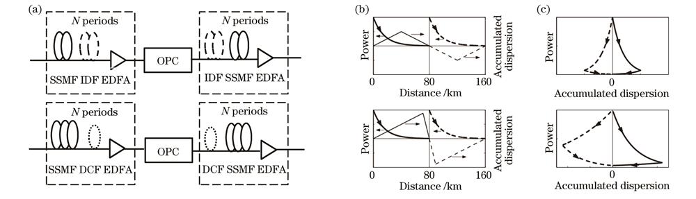
Fig. 1. Transmission schemes and OPC propagation symmetry analysis. (a) Schematic of the IDF-managed (top) and DCF-managed (bottom) links; (b) corresponding power varying with transmission distance in case of two-span transmission (N=1); (c) PADD
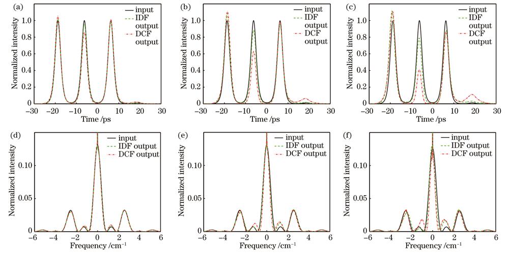
Fig. 2. Comparison of compensation performance of two transmission schemes for different transmission distance. Output pulse shapes of (a) two-span transmission, (b) six-span transmission, and (c) ten-span transmission; corresponding output spectra of (d) two-span transmission, (e) six-span transmission, and (f) ten-span transmission
Fig. 3. Comparison of compensation performance of two compensation schemes. Variation of ΔPaver with input energy for (a) two-span transmission, (b) six-span transmission, and (c) ten-span transmission; variation of relative peak intensity of ghost pulse with input energy for (d) two-span transmission, (e) six-span transmission, and (f) ten-span transmission
Fig. 4. Scheme for asymmetric power (energy) transmission [scheme is identical to DCF-managed link shown in Fig. 1(a) added with VGA and VOA]
Fig. 5. Relationship between compensation effect and E1/E2 for DCF scheme under six-span transmission. (a) Variation of ΔPaver with E1/E2; (b) variation of relative peak intensity of ghost pulse with E1/E2
Fig. 6. Comparison of output results of asymmetric energy transfer and symmetric energy transfer for DCF scheme. (a) Waveform comparison; (b) spectrum comparison
|
Table 1. Fiber parameters set for simulations

Set citation alerts for the article
Please enter your email address
© Copyright 2018-2021 | Chinese Laser Press. All Rights Reserved 沪ICP备15018463号-20