• Acta Optica Sinica
  • Vol. 41, Issue 14, 1415001 (2021)
Peigen Ye, Ze Yang, Yanbiao Sun*, and Jigui Zhu
Author Affiliations
  • State Key Laboratory of Precision Measuring Technology and Instruments, Tianjin University, Tianjin 300072, China
  • show less
    DOI: 10.3788/AOS202141.1415001 Cite this Article Set citation alerts
    Peigen Ye, Ze Yang, Yanbiao Sun, Jigui Zhu. Oblique Image Orientation Method Based on Local-to-Global Optimization Strategy[J]. Acta Optica Sinica, 2021, 41(14): 1415001 Copy Citation Text show less
    Working principle of five camera oblique photography device. (a) Five images captured in 3D object space; (b) plane-directional distribution of five images captured on an exposure station
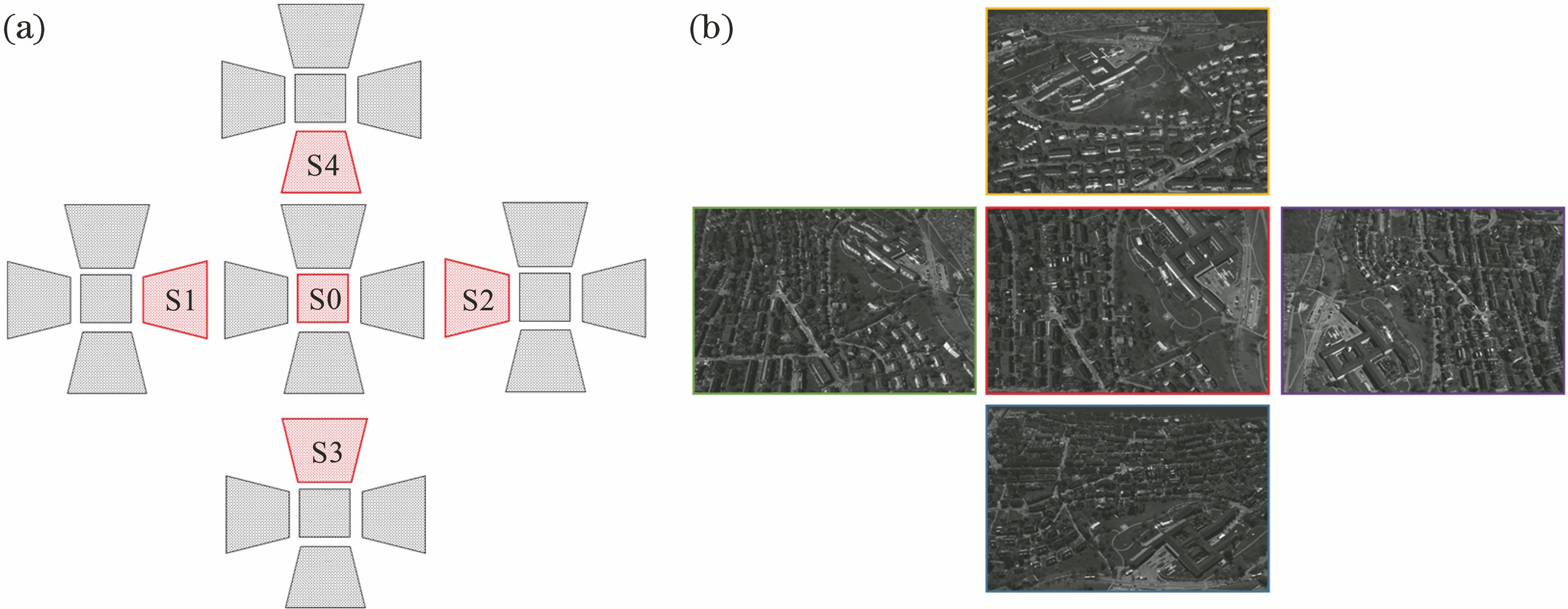
    Fig. 1. Working principle of five camera oblique photography device. (a) Five images captured in 3D object space; (b) plane-directional distribution of five images captured on an exposure station
    There is a large overlap between the images on five different exposure stations. (a) Plane-directional distribution of the five exposure stations; (b) an example of local map from ISRPS EuroSDR dataset
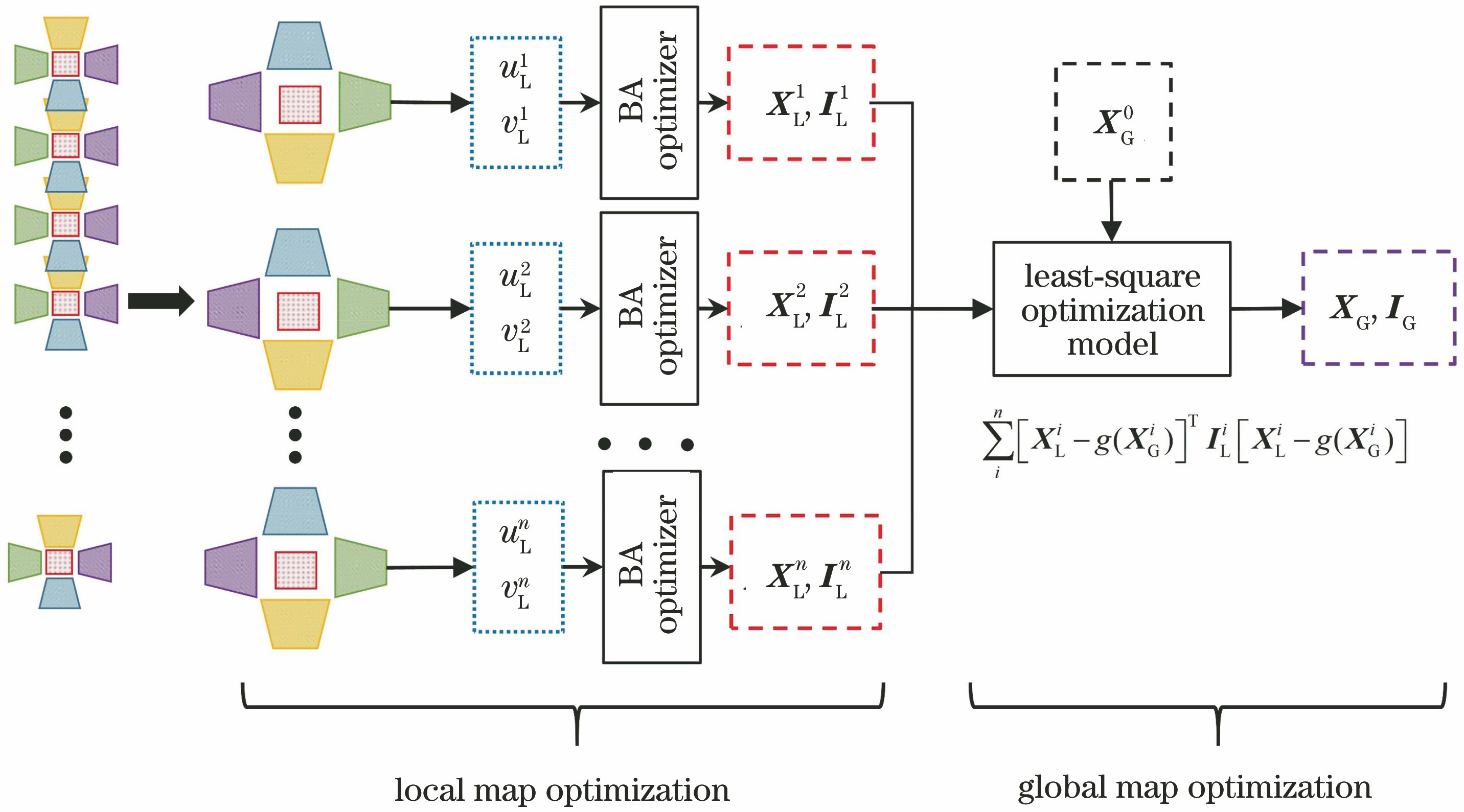
    Fig. 2. There is a large overlap between the images on five different exposure stations. (a) Plane-directional distribution of the five exposure stations; (b) an example of local map from ISRPS EuroSDR dataset
    Principle structure of the LGO method
    Fig. 3. Principle structure of the LGO method
    Combining all local maps into a global map by a least-square optimization
    Fig. 4. Combining all local maps into a global map by a least-square optimization
    Spatial distribution of the exposure stations over the observed terrain
    Fig. 5. Spatial distribution of the exposure stations over the observed terrain
    Trajectories of the nadir cameras of the exposure stations
    Fig. 6. Trajectories of the nadir cameras of the exposure stations
    Change of MSE with the number of iterations. (a) MSE of the BA method; (b) MSE of the LGO method
    Fig. 7. Change of MSE with the number of iterations. (a) MSE of the BA method; (b) MSE of the LGO method
    Residual of all estimated camera positions
    Fig. 8. Residual of all estimated camera positions
    Distribution of the 135 Zurich images and the construction of local maps
    Fig. 9. Distribution of the 135 Zurich images and the construction of local maps
    Trajectories for the Zurich data. (a) Trajectory of only nadir images; (b) Trajectory of both nadir and side images
    Fig. 10. Trajectories for the Zurich data. (a) Trajectory of only nadir images; (b) Trajectory of both nadir and side images
    Change of MSE with the number of iterations on the Zurich dataset. (a) BA method; (b) LGO method
    Fig. 11. Change of MSE with the number of iterations on the Zurich dataset. (a) BA method; (b) LGO method
    Residual of 135 Zurich images estimated by the BA and LGO methods. (a) X direction; (b) Y direction; (c) Z direction; (d) 3D
    Fig. 12. Residual of 135 Zurich images estimated by the BA and LGO methods. (a) X direction; (b) Y direction; (c) Z direction; (d) 3D
    ParameterValue
    Area/(km×km)60×7
    Number of track points10
    Number of images5000
    Number of local maps1000
    Number of 3D points54337
    Number of projection points490086
    Table 1. Parameters of the large scale simulated dataset
    ParameterBALGO
    X9.65639.6516
    Y5.06195.0623
    Z0.83620.8568
    3D6.31316.3117
    Table 2. RMSE of camera positions estimated by the BA and the LGO methodsunit: m
    ConditionBA methodLGO method
    Initial MSEFinal MSENumber ofiterationsInitial MSEFinal MSENumber ofiterations
    XYZ+5 m1.922×1030.01242.352×1030.0043
    XYZ+50 m1.998×1050.01252.425×1050.0045
    XYZ+100 m7.930×1050.01261.288×1060.0046
    XYZ+200 m3.594×106Singular5.828×1060.0049
    XYZ+300 m2.375×1013Singular3.188×1013Singular
    Ang+0.1 rad8.903×105Singular9.805×1050.0045
    Ang+0.2 rad3.823×106Singular4.013×1068.34322
    Ang+0.25 rad1.019×107Singular6.496×106Singular
    Ang+0.3 rad2.022×107Singular9.538×106Singular
    Ang+0.4 rad1.803×1012Singular1.677×107Singular
    Table 3. Results of BA and LGO methods on the large scale simulated dataset with initialization noise
    ParameterContent
    Camera typeLeica RCD30 Oblique Penta
    Image size /(pixel×pixel)9000×6732
    Focal length /mm53
    Pixel size /mm0.006
    Platform height /m1000
    Title angles /(°)35
    Along-track overlap /%70
    Across-track overlap /%50
    Ground sample distance(GSD) /cm6--12
    Number of images135
    Number of 3D points51672
    Number of projection points225952
    Table 4. Overall parameters of the used Zurich dataset
    IndicatorBALGO
    Initial MSE2.416×1061.838×108
    Final MSE0.9890.282
    Number of iterations84
    RMSE along X-axis /m0.18960.1817
    RMSE along Y-axis /m0.17040.1752
    RMSE along Z-axis /m0.15270.1535
    RMSE in 3D space /m0.17150.1705
    Table 5. Parameters of the BA method and the proposed method for Zurich data
    ConditionBA methodLGO method
    Initial MSEFinal MSENumber ofiterationsInitial MSEFinal MSENumber ofiterations
    XYZ+5 m4.337×1030.98954.383×1030.3803
    XYZ+50 m4.879×1050.98964.818×1050.3803
    XYZ+100 m1.352×1060.98981.288×1060.3803
    XYZ+200 m6.971×106Singular5.498×1060.3803
    XYZ+300 m3.687×1012Singular1.677×1070.3803
    Ang+0.1 rad4.119×1050.98964.003×1050.3805
    Ang+0.2 rad1.897×1060.98971.675×1060.3806
    Ang+0.25 rad3.260×1060.98972.593×1060.3807
    Ang+0.3 rad4.419×1060.98983.349×1060.3807
    Ang+0.4 rad8.364 ×108Singular6.680×1060.3808
    Table 6. Results of BA and LGO methods on the Zurich dataset with initialization noise
    Peigen Ye, Ze Yang, Yanbiao Sun, Jigui Zhu. Oblique Image Orientation Method Based on Local-to-Global Optimization Strategy[J]. Acta Optica Sinica, 2021, 41(14): 1415001
    Download Citation