
Qiongxin Liang, Jinlong Huang, Nian Pan, Kewei Chen. Alignment Method of a Large Aperture Telescope Based on the Eigen Coefficient[J]. Laser & Optoelectronics Progress, 2021, 58(12): 1211001
- Laser & Optoelectronics Progress
- Vol. 58, Issue 12, 1211001 (2021)
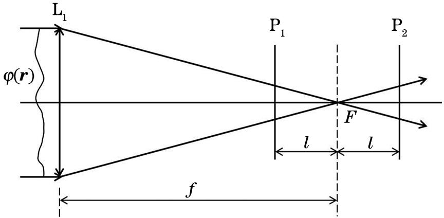
Fig. 1. Optical principle of wavefront curvature sensor
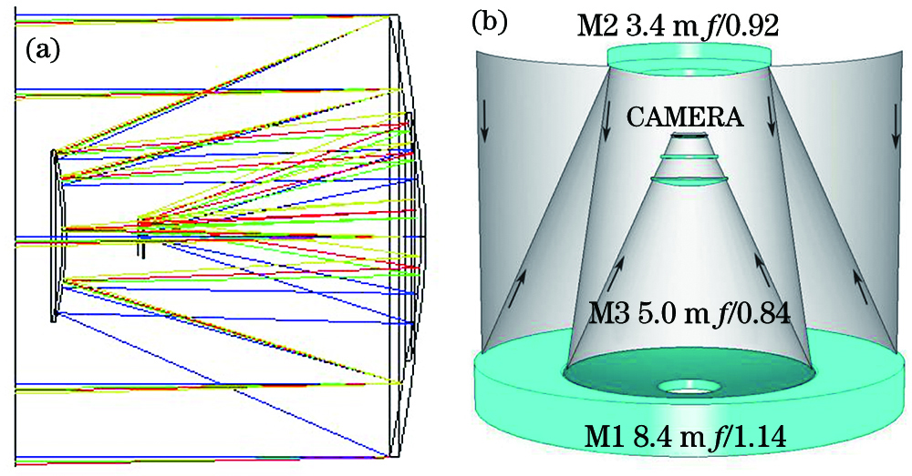
Fig. 2. optical system structures. (a) 1 m on-axis three-mirror optical system structure; (b) 8.4 m LSST optical system structure
Fig. 3. Relationship between eigenmode coefficient on the annular pupil and the degrees of freedom. (a) Dx; (b) Dy; (c) Tx; (d) Ty; (e) Dz
Fig. 4. Axial decentered spot pattern of secondary mirror. (a) Front defocusing plane; (b) focal plane; (c) back defocusing plane
Fig. 5. Horizontal decentered spot pattern of wavefront curvature sensor. (a) Front defocusing plane; (b) focal plane; (c) back defocusing plane
Fig. 6. Tilted spot pattern of wavefront curvature sensor. (a) Front defocusing plane; (b) focal plane; (c) back defocusing plane
Fig. 7. Defocus spot pattern of wavefront curvature sensor. (a) Front defocusing plane; (b) focal plane; (c) back defocusing plane
Fig. 8. Horizontal decentered or tilted spot pattern of secondary mirror. (a) Front defocusing plane; (b) focal plane; (c) back defocusing plane
|
Table 1. Eigenmode coefficient on the annular pupil
|
Table 2. Eigenmode coefficient sensitivity matrix of design state
|
Table 3. Misalignment introduced by the secondary mirror
| |||||||||||||||||||||||||||||||||||||||||||||||||||||||||||||||||||||||||||||||||||||||||||||||||||||||||||||||||||||||||||||||||||||||||||||||
Table 4. Misalignment before and after A1 alignment
| |||||||||||||||||||||||||||||||||||||||||||||||||||||||||||||||||||||||||||||||||||||||||||||||||||||||
Table 5. Misalignment before and after A2 alignment

Set citation alerts for the article
Please enter your email address
© Copyright 2018-2021 | Chinese Laser Press. All Rights Reserved 沪ICP备15018463号-20