
Akira Kon, Mamiko Nishiuchi, Yuji Fukuda, Kotaro Kondo, Koichi Ogura, Akito Sagisaka, Yasuhiro Miyasaka, Nicholas P. Dover, Masaki Kando, Alexander S. Pirozhkov, Izuru Daito, Liu Chang, Il Woo Choi, Chang Hee Nam, Tim Ziegler, Hans-Peter Schlenvoigt, Karl Zeil, Ulrich Schramm, Hiromitsu Kiriyama, "Characterization of the plasma mirror system at the J-KAREN-P facility," High Power Laser Sci. Eng. 10, 04000e25 (2022)
- High Power Laser Science and Engineering
- Vol. 10, Issue 4, 04000e25 (2022)
Abstract
1 Introduction
With the chirped pulse amplification (CPA) technology invented in 1985[1], research using high-intensity lasers has evolved for various applications[2,3]. Recently, the development of ultrahigh-power lasers and spatio-temporal control techniques, such as deformable mirrors and an optical parametric chirped pulse amplifier (OPCPA), has enabled the focused intensity to reach 1022–1023 W/cm2[4–8]. In laser-plasma experiments, pre-plasma formation on the target owing to the poor temporal contrast has become a significant problem preventing the interaction with an ultraintense laser pulse, as the focused intensity increases[9,10]. The sources of such pre-pulse and/or pedestal in the poor contrast include amplified spontaneous emission[11], higher-order dispersion[12], clipping of the spectrum or scattering from the diffraction gratings[13] and non-linear optical effects[14]. These are so intricately intertwined that it is difficult to eliminate them. To solve these problems, various methods have been developed to improve temporal contrast actively, including Pockels cells, cross-polarized waves[15], saturable absorbers[16], second harmonic conversion[17] and plasma lens filters[18]. Plasma mirrors (PMs)[19–21] have been adopted in many experimental facilities to improve temporal contrast at full power with TW to PW lasers after pulse compression, just before the target. This means that PMs can reduce all pre-pulses and pedestals inherent to the laser system. PMs enhance the temporal contrast by preferentially reflecting the highest intensity part of the pulse while minimizing the reflection of the preceding light. An anti-reflective (AR) coating is applied to a substrate, which, when irradiated at an appropriate fluence, is ionized at the leading edge of the main pulse. The main pulse is strongly reflected by the self-generated plasma on the mirror. On the other hand, the pre-pulse and pedestal do not reach a sufficient fluence to ionize the PM and are therefore attenuated in reflection by the AR coating. As the reflectivity of the ionized PM at optimum fluence exceeds the AR coating reflectivity by more than an order of magnitude, the PM can dramatically reduce pre-pulses and pedestals and thus improve temporal contrast. For more than a decade, high-contrast pulses with PMs have been a major contribution to the studies of high-order harmonic generation[22–26] and ion acceleration[27–31]. PMs have the disadvantage that the PM substrate must be exchanged after irradiation, but various methods have been developed in recent years, such as using a flowing liquid[32] or moving a large PM at high speed[33]. In addition, various applications have been developed, such as PMs with focusing ability[34], high reflectivity[35], frequency-resolved optical gating[36], multi-stage laser wakefield acceleration[37] and electron–photon interaction[38]. Therefore, PMs have been developed and improved by many high-power laser facilities worldwide.
There are two main ways of implementing PMs to improve the temporal contrast. One is to install the PM as the final optic just before the target irradiation. The other is to use two optics focusing laser pulse onto the PM, and then recollimating and guiding the contrast-enhanced pulse to the irradiation chamber. The former has the advantage of easy installation, but the number of shots is limited due to close positioning around the target, the reflectivity of the PM being low due to the polarization of the laser and the low F-number of the off-axis parabolic (OAP) making it difficult to install a double PM. On the other hand, the latter method enables a relatively large number of laser shots and can obtain high reflectivity by optimizing the fluence and other factors. The disadvantage of the latter method is that, due to the large beam diameter of petawatt-class laser systems (typically >200 mm), the construction cost is high and securing a suitable installation site is a significant problem. Table 1 summarizes the PM performance of various laser facilities equipped with a PM system[39–58]. There are differences in the design of the system and the performance of the laser, but they are routinely used to improve temporal contrast by a factor of 100 or more. On the other hand, to use PMs, it is essential to measure the reflectivity and spatial and temporal distribution[20,21]. Optimal conditions for the use of PMs differ slightly from one facility to another. This is because the performance of the PM system depends on several factors, including the parameters of the laser and the setup. Recently, PMs have been planned for use not only in relatively large laser systems of several hundred terawatts, but also in laser facilities of 10 PW or more[59,60]. The maximum beam diameter in the final compressor of J-KAREN-P is approximately 280 mm, and the system consists of optical components capable of multi-PW class output. An interaction experiment using the laser has been conducted at a power output of approximately 200 TW, and these performances and configurations, shown in Table 1, will provide useful guidelines for designing PM systems with output of several hundred terawatts.
| Maximum | Temporal | ||||
|---|---|---|---|---|---|
| Laser power | reflectivity of | contrast | |||
| Laser name or laser facility | (TW) | PM system design | PM system (%) | enhancement | References |
| Hercules | 300 | Double | 50 | 105 | [ |
| BELLA Petawatt Laser | 1000 | Single (VHS tape) | 80 | [ | |
| Scarlet | 400 | Single (liquid crystal) | 75 | 350 | [ |
| Advanced Laser Light Source | 200 | Double | 55 | 104 | [ |
| Astra-Gemini | 500 | Double | 65 | 104 | [ |
| Salle Jaune | 100 | Double | 50 | 104 | [ |
| UHI100 | 100 | Double | 50 | 104 | [ |
| JETI | 10 | Single | 80 | 103 | [ |
| ATLAS | 300 | Double | 40 | 103–104 | [ |
| Max-Born-Institute | 35 | Double | 60 | 104 | [ |
| DRACO | 150 (1000) | Single | 90 (85) | 102–103 | [ |
| ARCTURUS | 100 | Single | 80 | 102 | [ |
| POLARIS | 170 | Single | 600 | [ | |
| Lund Laser Center | 10 | Double | 40 | 102 | [ |
| Laboratory for Laser Plasmas | 200 | Single | 70 | 102 | [ |
| CoReLS 4-PW laser | 4000 | Double | 70 | 7×10⁶ | [ |
| T6-laser | 10 | Single | 70 | 104 | [ |
| J-KAREN-P | 200 | Single | 85 | 102 | This work |
Table 1. Performance and design of PM systems in laser facilities around the world.
In this paper, we report in detail the performance of a single PM system installed in the J-KAREN-P facility. Firstly, the components of the PM system are described in detail. Next, we describe the measured reflectivity, temporal contrast and pulse width of the PM system. In addition, changes in spatial distribution, energy and pointing stability are reported.
Sign up for High Power Laser Science and Engineering TOC. Get the latest issue of High Power Laser Science and Engineering delivered right to you!Sign up now
2 Plasma mirror system on the J-KAREN-P laser facility
The J-KAREN-P laser is a double-CPA Ti:sapphire laser system with OPCPA stages[61,62]. After the final stage compressor, a 200 TW (10 J, 50 fs) laser beam with a diameter of 250 mm was delivered to the experimental area. Owing to the nonuniformity of the intensity distribution of the near-field (NF) pattern, the laser power was limited in this experiment. As shown in Figure 1(a), the PM system was installed after the final compressor and before the target chamber. The size of the vacuum chamber of the PM system (TOYAMA Co., Ltd) was 2.1 m × 2.7 m × 2.3 m (Figure 1(b)). The minimal achievable pressure of the chamber was approximately 10–5 Pa. The PM system consisted of two periscope pairs, two OAP mirrors and a PM substrate (Figures 1(c)–1(e)). As the laser polarization was in the horizontal plane after the compressor, we used the periscopes to facilitate irradiation of the PM with s-polarized light. Note that the periscopes were adopted to obtain high reflectivity by using the p-polarized light on the future double PM[57]. The mirror holders of the periscopes were the ANTARES series made by LIOP-TEC GmbH, which were adjusted using piezo actuators (Physik Instrumente (PI) GmbH & Co. KG). The flat mirror was a dielectric multilayer mirror made by Korea Electro-Optics Co., Ltd (KEOC), which had a dichroic coating reflecting not only at the 770–830 nm wavelength of the high-power laser but also at the 630 nm wavelength of a co-propagating red alignment laser. The OAPs (TYDEX. LLC) had a focal length of 2 m (F/8) and a wavefront accuracy of λ/10 (peak-to-valley) at 633 nm. The OAPs were installed on a five-axis (XY, θxθyθz) automated stage (Kohzu Precision Co., Ltd). The setup was a ‘single’ PM, as shown in Figure 1(e). The size of the PM substrate was 400 mm × 70 mm × 30 mm, and the laser was incident on the mirror with s-polarization at an incidence angle of 16 degrees. The reflectance of the AR coating on both sides, calculated by KEOC, was less than 1% at 770–830 nm wavelengths with a 16-degree incidence angle. The total reflectance of the AR coating, taking into account the spectrum of the laser, is 0.8% ± 0.1%. This assumes that the wavelengths of the pre-pulse and pedestal are the same as the main pulse. Note that the AR-coated mirror used in this experiment does not have an optimal angle of incidence, as the mirror is designed to have the lowest reflectivity at a 37-degree incidence angle, which will be employed for our future double PM setup. There were silver-coated areas on the top, bottom and centre for the alignment of the PM substrate. The PM was placed on an automated stage (Kohzu Precision Co., Ltd) for XYZ and θx. The mirror could be moved between shots over a total range of ±250 mm in the vertical direction and ±35 mm in the horizontal direction. Assuming each irradiation makes a damage spot of a few millimetres on the substrate surface, each mirror can withstand about 1000 shots without replacement.
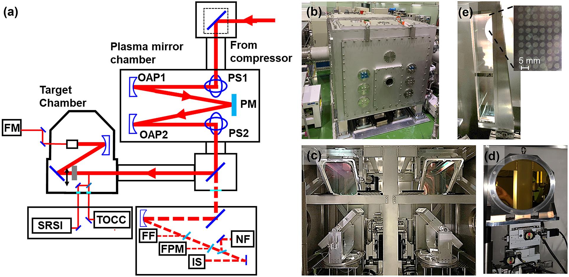
Figure 1.Layout and picture of the plasma mirror system at J-KAREN-P. (a) Layout of the PM setup. OAP, off-axis parabolic mirrors; PS, periscope; NF, near-field image camera; FF, far-field image camera; FPM, focus monitor on the PM; IS, integrating sphere and spectrometer; TOCC, third-order cross-correlator; SRSI, self-referenced spectral interferometry; FM, focus monitor. (b) PM chamber. (c) Periscope pair. (d) OAP and stage. (e) Substrate of single PM and damage pattern.
3 Measurement setup and characterization of the plasma mirror system
3.1 The reflectivity of the plasma mirror system
The measurement setup for the characterization of the PM system is shown in Figure 1(a). The temporal distribution was measured using the laser pulse picked off from the full beam with a diameter of 1 inch (1 inch = 2.54 cm). The energy and spatial distributions, on the other hand, were measured by down-collimating the full beam transmitted through a dielectric mirror after the PM chamber. The reflectivity of the PM system was calculated using an energy-calibrated charge-coupled device (CCD) camera after the final stage amplification, an absolutely calibrated integrating sphere and spectrometer installed after the PM for each shot. The measurement results included not just the reflectivity of the PM but also the reflectivity of the OAPs and flat mirrors in the PM system. Note that the throughput efficiency of the beamline optics (gratings, mirrors, windows, etc.) is 60% without the PM system. In the experiment, the overall reflectivities were obtained when the laser fluence on the PM was varied by changing the distance of the OAP to the PM and the laser energy. The fluence was calculated from the image on the PM measured with a lens and CCD after the PM system (FPM in Figure 1(a)). The error bars in the energy indicate the measurement error of the energy meter.
Figure 2 shows the overall reflectivity of the PM system. The reflectivity increased as the fluence increased, reaching 85% at a fluence of roughly 500 kJ/cm2. Such a high reflectivity has been measured in this fluence region (intensity ~1 × 10¹⁹ W/cm2) in previous studies[63]. The reflectivity of PMs varies significantly with the spatio-temporal profile of PM generation. The actual spatial and temporal distribution of the laser pulse on the PM is not an ideal flat-top or Gaussian profile. Thus, for example, if the spatial distribution of the laser is nonuniform, that is, there are many parts of the laser that do not ionize and are not reflected, the reflectivity will decrease. In the temporal distribution, if the light is not ideally compressed, the timing of ionization is delayed, more light is not reflected and the reflectivity is decreased. The improvements of spatial and temporal distribution have recently resulted in relatively high reflectivity[40]. The shot-to-shot variation of the laser energy with and without the PM is shown in Figure 3. Over 40 shots, the energy without the PM is (9.0 ± 0.31 J) and with the PM is (5.9 ± 0.26 J). The relative standard deviation of energy per shot was 3.4% without the PM and 4.4% with the PM. The difference with and without the PM (~1%) is due to the variation in the energy of the original incident laser. This means that the PM did not impede the energy stability significantly. In addition, energy fluctuations of 10 shots in each fluence (0.1, 0.5, 2.5, 7.5 and 50 kJ/cm2) are shown in Figure 3(b). The shot-to-shot trends after and before the PM of energy do not vary significantly with each fluence. Moreover, the relative standard deviation at each fluence was 2%–4%, and 3% without the PM. The energy fluctuations are largely independent of the fluence.
![]()
Figure 2.Reflectivity of the plasma mirror system. The vertical axis shows the reflectivity estimated from the energy acquired before and after the PM system. The horizontal axis shows the fluence and the intensity of the PM, whose value was estimated by measuring the spot size on the PM. The inset image shows spots on the PM (500 J/cm2) obtained with the focus monitor on the PM (FPM; Figure 1(a)).
![]()
Figure 3.(a) Shot-to-shot energy variation during 40 shots without (9.0 ± 0.31 J) and with (5.9 ± 0.26 J) the PM. (b) Shot-to-shot energy variation during 10 shots at each fluence (0.1, 0.5, 2.5, 7.5 and 50 kJ/cm2), without the PM and before the PM for the same shots. The circles and triangles represent energy after the PM. Energy before the PM is shown with diamonds.
3.2 Pulse duration and temporal contrast
Pulse duration and temporal contrast were measured using a self-referencing spectral interferometer (WIZZLER, Fastlite)[64] and a third-order cross-correlator (SEQUOIA, Amplitude Technologies). The pulse duration was optimized using J-KAREN-P’s power-amp mode (1 J, 10 Hz) by a feedback loop control using an acousto-optic device (DAZZLER, Fastlite)[65] before the measurement with the PM. For this dataset, the fluence on the PM was chosen to be 500 J/cm2, because the PM operation with high fluence and high reflectivity would increase the chance of optical damage due to the change of the NF profile or improper management (e.g., repeated shots without moving the PM substrate). Experiments could be conducted safely with a large number of shots at 500 J/cm2 (~65%). Comparisons were made with and without the PM system; the laser amplification conditions for the two sets of data were the same. The temporal contrast with and without the PM system is shown in Figure 4. From –10 ps to several hundred fs before the arrival of the main pulse, the contrast was improved by about a factor of 100. The trigger time for the PM was expected to be from –0.9 to –0.3 ps from two data points with and without the PM in the inset of Figure 4. The dotted line in Figure 4 shows the predicted contrast with a PM, considering the reflectivities of the PM (65%) and the AR coating (0.8%). This estimate assumes a constant reflectivity (65%) after the PM is activated and does not account for the temporal evolutions of the reflectivity[66]. However, the results of this estimation and the measurements are in good agreement before –0.3 ps.
![]()
Figure 4.Temporal contrast with (red line) and without (blue line) the PM. The dotted line is the temporal contrast estimated using the reflectance of the PM (65%) and AR coating (0.8%). The inset figure is an enlarged plot showing detail around the peak of the pulse. From the data points with and without the PM, the trigger time range for the PM is from –0.9 to –0.3 ps.
Figure 5(a) shows the measured pulse duration with an average of 100 shots. The full width at half maximum (FWHM) pulse duration with and without the PM are 47 ± 1.4 fs and 45 ± 1.0 fs, respectively. However, a 2% pre-pulse at approximately 140 fs was generated when the PM was used as depicted by the arrow in Figure 5(b).
![]()
Figure 5.One hundred shots average of pulse duration measurement from the self-referenced spectral interferometer: (a) linear scale; (b) log scale. The error bars correspond to statistical variations. The arrow in (b) shows the pre-pulse generated when using the PM.
The pulse width variation for each shot is also shown in Figure 6. The shot-to-shot stability did not change significantly when the PM was used. The spectrum was measured using an integrating sphere by focusing the full laser beam transmitted through a dielectric mirror onto the aperture of the integrating sphere. The spectra shown in Figure 7 have FWHMs of 26 ± 2 nm and 28 ± 2 nm with and without the PM, respectively, and no significant changes were measured.
![]()
Figure 6.Shot-to-shot fluctuation of pulse duration (FWHM): without the PM, 47 ± 1.4 fs; with the PM irradiated with a fluence of 500 J/cm2, 45 ± 1.0 fs.
![]()
Figure 7.The spectrum of 10 shots average with and without the PM. The fluence of PM irradiation is 500 J/cm2. The error bars correspond to standard deviations of statistical variations.
3.3 Spatial distribution (far-field image and near-field image)
To measure the spatial distribution of the laser, far-field (FF) and NF images were measured. The full beam, transmitted through a dielectric mirror, was focused using an OAP with an F-number of 8, and the magnified FF image was acquired using an objective lens and CCD camera. The NF was measured by imaging the beam profile 3 m after the PM. The results of the NF image measurements are shown in Figure 8(a), and it is clear from the XY line profiles that the intensity distribution changed significantly at fluences higher than 500 kJ/cm2 (~1 × 10¹⁹ W/cm2). The reason for the change in the NF is that the fluence of some parts of the spatial distribution is higher and thus ionizes the substrate earlier than regions of lower fluence[50,67]. The results of the FF when the fluence is varied by changing the distance of the OAP to the PM are shown in Figure 8(b). No significant change could be seen at 100 kJ/cm2. Note that due to the limitation of the travel range of the OAP drive stage, FF images with fluence higher than 100 kJ/cm2 have not been measured.
![]()
Figure 8.Spatial profiles: (a) NF image; (b) FF image. The laser fluence on the PM is written above.
3.4 Spot size measurement and pointing stability after focusing by OAP (F/1.3)
Figure 9 shows the focal spot distribution using the OAP (F/1.3) installed in the target irradiation chamber. This measurement was taken using a strongly attenuated Ti:sapphire laser for focusing adjustment. Therefore, these measurements only measure the impact of the PM substrate and additional beamline optics on the focal spot quality, and do not include any influence of ionizing the substrate when triggering the PM. The PM substrate was positioned such that the Ag coating reflected the alignment beam, and no plasma was ignited. The laser fluence was too low to activate the PM. The spot size FWHM was found to be X: 1.57 μm, Y: 1.65 μm when bypassing the PM system, and X: 1.66 μm, Y: 1.59 μm with the PM. In addition, the peak intensity average of 100 shots was (1.98 ± 0.28) × 1021 W/cm2 without the PM and (1.72 ± 0.24) × 1021 W/cm2 with the PM. This value was calculated using the integrated signal value as 100 TW[6], and the error is the standard deviation. Note that it is assumed that the focused intensity measured by the alignment laser remains the same in the case of PM triggering. From the results of this estimate, the peak intensity did not decrease even when the PM system was used. This indicates that the addition of the extra periscopes and OAPs of the PM system into the laser beamline did not severely affect the wavefront.
![]()
Figure 9.Focus spot images from the alignment laser (<μJ) after focusing by the OAP (
The stability of the pointing of the beam at the focal point (100 shots) was measured (Figure 10). This measurement was again made without activating the PM. The stability was found to be X: 1.11 μrad, Y: 1.22 μrad without the PM, and X: 1.99 μrad, Y: 2.07 μrad with the PM. This difference may be due to the vibration of the optical components (OAP and periscope) of the PM system and the vacuum chamber.
![]()
Figure 10.Pointing stability of the alignment laser (<μJ) with the OAP (
4 Discussion and outlook
The main performance of the PM system installed in J-KAREN-P is shown in Table 2. The results with the PM system (0.5 and 100 kJ/cm2) are summarized and compared to the beam parameters bypassing the PM; with the PM, the focused intensity at the target decreases, which is primarily due to absorption at the PM. The shot-to-shot variation of energy and pulse width does not change significantly with the use of the PM. This indicates that the stability is equivalent to that without the PM. Note that, for the last measurement, the focal spot in the target chamber was measured using a laser that was attenuated for alignment. Therefore, the PM is not activated at the time of this measurement. However, the NF and FF images (Figures 8(a) and (b)), of the on-shot diagnostic when the PM is activated showed no significant change in the focusing spot size even when the fluence is changed in the range of 0.1–100 kJ/cm2 (1015–1018 W/cm2). These results indicate that the degradation of the spatial distribution is likely to be small when the PM is used in normal operation. However, it would be ideal to directly measure the focal spot in the target chamber when using an activated PM. There have been various techniques introduced to measure the at-target focal spot for full power shots, including attenuation[68], backscatter focus[69] and measurement of high-order harmonics[70].
| Energy on | Temporal contrast | Pulse duration | Spot size | Pointing | Peak intensity | |
|---|---|---|---|---|---|---|
| target (J) | at –10 ps | FWHM (fs) | FWHM (μm) | (μrad, RMS) | (W/cm2) | |
| Without PM | 9.0 ± 0.31 | 10–7 | 47 ± 1.4 | X: 1.57 | X: 1.11 | (3.8 ± 0.6) × 1021 |
| Y: 1.65 | Y: 1.22 | |||||
| PM | 5.9 ± 0.26 | 10–9 | 45 ± 1.0 | X: 1.66 | X: 1.99 | (2.3 ± 0.3) × 1021 |
| (0.5 kJ/cm2) | (RPM ≃ 65%) | Y: 1.59 | Y: 2.07 | |||
| PM | 7.0 ± 0.34 | X: 1.66 | X: 1.99 | (2.9 ± 0.4) × 1021 | ||
| (100 kJ/cm2) | (RPM ≃ 83%) | Y: 1.59 | Y: 2.07 |
Table 2. Summary of the characteristics of the PM system in J-KAREN-P. Note that the focus spot size and pointing stability are measured with alignment mode laser (<μJ). Note that the PM dataset is from a highly reflective coated part of the PM substrate, rather than an activated PM. The peak intensities are calculated from the on-target energy, pulse duration and focused intensity, respectively.
The temporal contrast is in good agreement with the results obtained by considering the reflectivity of the AR coating and the reflectivity of the PM. The temporal contrast could still be improved further by one to two orders of magnitude by optimizing the AR coating[46,58]. In addition, we are also planning to introduce a second PM to achieve even higher contrast. On the other hand, in the case of the PM, a new pre-pulse is measured at approximately –140 fs (Figure 6(b)). This may be because of the PM, but the cause is still under investigation. This is a major problem in experiments where minimizing the laser energy in the rising edge of the pulse is important[51,71], although it can be suppressed by feedback control using acousto-optic elements.
In addition, the temporal contrast was measured several times over 300 shots on the same PM substrate, and no degradation of temporal contrast or reflectivity due to debris accumulation on the PM substrate was observed. This implies that lateral debris spread from plasma ablation with a single PM is not significant. On the other hand, debris shielding is likely to be essential if two mirror substrates are in proximity, as in the case of a double PM.
In the future, we plan to conduct experiments using a contrast-enhanced laser pulse (e.g., ion acceleration[27–31]). Following this, we will upgrade to a double PM and introduce a deformable mirror after the compressor to further improve the laser quality.
5 Conclusion
In this paper, we have reported on the configuration and performance of a single PM system installed in the J-KAREN-P laser system. The maximum reflectivity of the PM system exceeded 80%. The temporal contrast was improved by nearly two orders of magnitude at times earlier than 1 ps before the main pulse. The wavelength spectrum and pulse width did not change significantly when the PM was used. It was found that the laser NF degraded significantly when the fluence was larger than 500 kJ/cm2 (~1 × 10¹⁹ W/cm2). The FF image did not change significantly in the fluence range of 0.1–100 kJ/cm2 (1015–1018 W/cm2). The shot-to-shot stability of the laser energy, pulse duration and pointing were not changed significantly when the PM system was used. In the future, we plan to carry out target irradiation experiments using a PM and upgrade our system to accommodate double PMs.
References
[1] D. Strickland, G. Mourou. Opt. Commun., 56, 219(1985).
[2] D. Umstadter. Phys. Plasmas, 8, 1774(2001).
[3] G. A. Mourou, T. Tajima, S. V. Bulanov. Rev. Mod. Phys., 78, 309(2006).
[4] S.-W. Bahk, P. Rousseau, T. A. Planchon, V. Chvykov, G. Kalintchenko, A. Maksimchuk, G. A. Mourou, V. Yanovsky. Opt. Lett., 29, 2837(2004).
[5] G. Tiwari, E. Gaul, M. Martinez, G. Dyer, J. Gordon, M. Spinks, T. Toncian, B. Bowers, X. Jiao, R. Kupfer, L. Lisi, E. McCary, R. Roycroft, A. Yandow, G. D. Glenn, M. Donovan, T. Ditmire, B. M. Hegelich. Opt. Lett., 44, 2764(2019).
[6] A. S. Pirozhkov, Y. Fukuda, M. Nishiuchi, H. Kiriyama, A. Sagisaka, K. Ogura, M. Mori, M. Kishimoto, H. Sakaki, N. P. Dover, K. Kondo, N. Nakanii, K. Huang, M. Kanasaki, K. Kondo, M. Kando. Opt. Express, 25, 20486(2017).
[7] Z. Guo, L. Yu, J. Wang, C. Wang, Y. Liu, Z. Gan, W. Li, Y. Leng, X. Liang, R. Li. Opt. Express, 26, 26776(2018).
[8] J. W. Yoon, Y. G. Kim, I. W. Choi, J. H. Sung, H. W. Lee, S. K. Lee, C. H. Nam. Optica, 8, 630(2021).
[9] M. Kaluza, J. Schreiber, M. I. K. Santala, G. D. Tsakiris, K. Eidmann, J. Meyer-ter-Vehn, K. J. Witte. Phys. Rev. Lett., 93, 045003(2004).
[10] S. P. D. Mangles, A. G. R. Thomas, M. C. Kaluza, O. Lundh, F. Lindau, A. Persson, Z. Najmudin, C.-G. Wahlström, C. D. Murphy, C. Kamperidis, K. L. Lancaster, E. Divall, K. Krushelnick. Plasma Phys. Control. Fusion, 48(2006).
[11] V. V. Ivanov, A. Maksimchuk, G. Mourou. Appl. Opt., 42, 7231(2003).
[12] S. Kane, J. Squier. J. Opt. Soc. Am. B, 14, 1237(1997).
[13] C. Hooker, Y. Tang, O. Chekhlov, J. Collier, E. Divall, K. Ertel, S. Hawkes, B. Parry, P. P. Rajeev. Opt. Express, 19, 2193(2011).
[14] N. V. Didenko, A. V. Konyashchenko, A. P. Lutsenko, S. Y. Tenyakov. Opt. Express, 16, 3178(2008).
[15] A. Jullien, O. Albert, F. Burgy, G. Hamoniaux, J.-P. Rousseau, J.-P. Chambaret, F. Augé-Rochereau, G. Chériaux, J. Etchepare, N. Minkovski, S. M. Saltiel. Opt. Lett., 30, 920(2005).
[16] J. Itatani, J. Faure, M. Nantel, G. Mourou, S. Watanabe. Opt. Commun., 148, 70(1998).
[17] J. Queneuille, F. Druon, A. Maksimchuk, G. Chériaux, G. Mourou, K. Nemoto. Opt. Lett., 25, 508(2000).
[18] P. Zhu, A. Zigler, X. Xie, D. Zhang, Q. Yang, M. Sun, J. Papeer, J. Kang, Q. Gao, X. Liang, H. Zhu, A. Guo, Y. Liang, S. Ji, L. Ren, H. Liu, N. Kang, Y. Zhao, J. Zhu. Opt. Lett., 45, 2279(2020).
[19] H. C. Kapteyn, A. Szoke, R. W. Falcone, M. M. Murnane. Opt. Lett., 16, 490(1991).
[20] G. Doumy, F. Quéré, O. Gobert, M. Perdrix, P. Martin, P. Audebert, J. C. Gauthier, J.-P. Geindre, T. Wittmann. Phys. Rev. E, 69, 026402(2004).
[21] B. Dromey, S. Kar, M. Zepf, P. Foster. Rev. Sci. Instrum., 75, 645(2004).
[22] I. Watts, M. Zepf, E. L. Clark, M. Tatarakis, K. Krushelnick, A. E. Dangor, R. Allott, R. J. Clarke, D. Neely, P. A. Norreys. Phys. Rev. E, 66, 036409(2002).
[23] B. Dromey, M. Zepf, A. Gopal, K. Lancaster, M. S. Wei, K. Krushelnick, M. Tatarakis, N. Vakakis, S. Moustaizis, R. Kodama, M. Tampo, C. Stoeckl, R. Clarke, H. Habara, D. Neely, S. Karsch, P. Norreys. Nat. Phys., 2, 456(2006).
[24] I. J. Kim, K. H. Pae, C. M. Kim, H. T. Kim, H. Yun, S. J. Yun, J. H. Sung, S. K. Lee, J. W. Yoon, T. J. Yu, T. M. Jeong, C. H. Nam, J. Lee. Nat. Commun., 3, 1231(2012).
[25] H. Vincenti, S. Monchocé, S. Kahaly, G. Bonnaud, P. Martin, F. Quéré. Nat. Commun., 5, 3403(2014).
[26] L. Chopineau, A. Denoeud, A. Leblanc, E. Porat, P. Martin, H. Vincenti, F. Quéré. Nat. Phys., 17, 968(2021).
[27] D. Neely, P. Foster, A. Robinson, F. Lindau, O. Lundh, A. Persson, C.-G. Wahlström, P. McKenna. Appl. Phys. Lett., 89, 021502(2006).
[28] A. Henig, S. Steinke, M. Schnürer, T. Sokollik, R. Hörlein, D. Kiefer, D. Jung, J. Schreiber, B. M. Hegelich, X. Q. Yan, J. Meyer-ter-Vehn, T. Tajima, P. V. Nickles, W. Sandner, D. Habs. Phys. Rev. Lett., 103, 245003(2009).
[29] S. Kar, K. F. Kakolee, B. Qiao, A. Macchi, M. Cerchez, D. Doria, M. Geissler, P. McKenna, D. Neely, J. Osterholz, R. Prasad, K. Quinn, B. Ramakrishna, G. Sarri, O. Willi, X. Y. Yuan, M. Zepf, M. Borghesi. Phys. Rev. Lett., 109, 185006(2012).
[30] I. J. Kim, K. H. Pae, I. W. Choi, C.-L. Lee, H. T. Kim, H. Singhal, J. H. Sung, S. K. Lee, H. W. Lee, P. V. Nickles, T. M. Jeong, C. M. Kim, C. H. Nam. Phys. Plasmas, 23, 070701(2016).
[31] A. McIlvenny, D. Doria, L. Romagnani, H. Ahmed, N. Booth, E. J. Ditter, O. C. Ettlinger, G. S. Hicks, P. Martin, G. G. Scott, S. D. R. Williamson, A. Macchi, P. McKenna, Z. Najmudin, D. Neely, S. Kar, M. Borghesi. Phys. Rev. Lett., 127, 194801(2021).
[32] P. L. Poole, A. Krygier, G. E. Cochran, P. S. Foster, G. G. Scott, L. A. Wilson, J. Bailey, N. Bourgeois, C. Hernandez-Gomez, D. Neely, P. P. Rajeev, R. R. Freeman, D. W. Schumacher. Sci. Rep., 6, 32041(2016).
[33] A. Borot, D. Douillet, G. Iaquaniello, T. Lefrou, P. Audebert, J.-P. Geindre, R. Lopez-Martens. Rev. Sci. Instrum., 85, 013104(2014).
[34] M. Nakatsutsumi, A. Kon, S. Buffechoux, P. Audebert, J. Fuchs, R. Kodama. Opt. Lett., 35, 2314(2010).
[35] G. G. Scott, V. Bagnoud, C. Brabetz, R. J. Clarke, J. S. Green, R. I. Heathcote, H. W. Powell, B. Zielbauer, T. D. Arber, P. McKenna, D. Neely. New J. Phys., 17, 033027(2015).
[36] R. Itakura, T. Kumada, M. Nakano, H. Akagi. Opt. Express, 23, 10914(2015).
[37] S. Steinke, J. van Tilborg, C. Benedetti, C. G. R. Geddes, C. B. Schroeder, J. Daniels, K. K. Swanson, A. J. Gonsalves, K. Nakamura, N. H. Matlis, B. H. Shaw, E. Esarey, W. P. Leemans. Nature, 530, 190(2016).
[38] K. T. Phuoc, S. Corde, C. Thaury, V. Malka, A. Tafzi, J. P. Goddet, R. C. Shah, S. Sebban, A. Rousse. Nat. Photon., 6, 308(2012).
[39] F. Dollar, C. Zulick, T. Matsuoka, C. McGuffey, S. S. Bulanov, V. Chvykov, J. Davis, G. Kalinchenko, G. M. Petrov, L. Willingale, V. Yanovsky, A. Maksimchuk, A. G. R. Thomas, K. Krushelnick. Phys. Plasmas, 20, 056703(2013).
[40] B. H. Shaw, S. Steinke, J. van Tilborg, W. P. Leemans. Phys. Plasmas, 23, 063118(2016).
[41] L. Lecherbourg, S. Fourmaux, C. Anca-Popovici, G. Lebrun, J. C. Kieffer, T. Ozaki, R. Marjoribanks. , , , , , , and , “Developing online plasma mirror for ALLS high contrast ALLS”, Annual Report (2009), p. ., 20.
[42] M. J. V Streeter, P. S. Foster, F. H. Cameron, R. Bickerton, S. Blake, P. Brummit, B. Costello, E. Divall, C. Hooker, P. Holligan, D. R. Neville, P. P. Rajeev, D. Rose, J. Suarez-Merchen, D. Neely, D. C. Carroll, L. Romagnani, M. Borghesi. , , , , , , , , , , , , , , , , , and , “Astra Gemini compact plasma mirror system,” CLF Annual Report (), p. ., 229(2009).
[43] N. Booth, S. Astbury, E. Bryce, R. J. Clarke, C. D. Gregory, J. S. Green, D. Haddock, R. I. Heathcote, C. Spindloe. Proc. SPIE, 10763, 107630S(2018).
[44] T. Wittmann, J. P. Geindre, P. Audebert, R. S. Marjoribanks, J. P. Rousseau, F. Burgy, D. Douillet, T. Lefrou, K. T. Phuoc, J. P. Chambaret. Rev. Sci. Instrum., 77, 083109(2006).
[45] A. Lévy, T. Ceccotti, P. D’Oliveira, F. Réau, M. Perdrix, F. Quéré, P. Monot, M. Bougeard, H. Lagadec, P. Martin, J.-P. Geindre, P. Audebert. Opt. Lett., 32, 310(2007).
[46] C. Rödel, M. Heyer, M. Behmke, M. Kübel, O. Jäckel, W. Ziegler, D. Ehrt, M. C. Kaluza, G. G. Paulus. Appl. Phys. B, 103, 295(2011).
[47] D. Kiefer. Relativistic Electron Mirrors(2015).
[48] A. A. Andreev, S. Steinke, T. Sokollik, M. Schnürer, S. T. Avetsiyan, K. Y. Platonov, P. V. Nickles. Phys. Plasmas, 16, 013103(2009).
[49] S. Steinke, P. Hilz, M. Schnürer, G. Priebe, J. Bränzel, F. Abicht, D. Kiefer, C. Kreuzer, T. Ostermayr, J. Schreiber, A. A. Andreev, T. P. Yu, A. Pukhov, W. Sandner. Phys. Rev. ST Accel. Beams, 16, 011303(2013).
[50] L. Obst, J. Metzkes-Ng, S. Bock, G. E. Cochran, T. E. Cowan, T. Oksenhendler, P. L. Poole, I. Prencipe, M. Rehwald, C. Rödel, H.-P. Schlenvoigt, U. Schramm, D. W. Schumacher, T. Ziegler, K. Zeil. Plasma Phys. Control. Fusion, 60, 054007(2018).
[51] T. Ziegler, D. Albach, C. Bernert, S. Bock, F.-E. Brack, T. E. Cowan, N. P. Dover, M. Garten, L. Gaus, R. Gebhardt, I. Goethel, U. Helbig, A. Irman, H. Kiriyama, T. Kluge, A. Kon, S. Kraft, F. Kroll, M. Loeser, J. Metzkes-Ng, M. Nishiuchi, L. Obst-Huebl, T. Püschel, M. Rehwald, H.-P. Schlenvoigt, U. Schramm, K. Zeil. Sci. Rep., 11, 7338(2021).
[52] M. Cerchez, R. Prasad, B. Aurand, A. L. Giesecke, S. Spickermann, S. Brauckmann, E. Aktan, M. Swantusch, M. Toncian, T. Toncian, O. Willi. High Power Laser Sci. Eng., 7(2019).
[53] S. Keppler, N. Elkina, G. A. Becker, J. Hein, M. Hornung, M. Mäusezahl, C. Rödel, I. Tamer, M. Zepf, M. C. Kaluza. Phys. Rev. Res., 4, 013065(2022).
[54] S. Vallières, M. Salvadori, A. Permogorov, G. Cantono, K. Svendsen, Z. Chen, S. Sun, F. Consoli, E. d’Humières, C.-G. Wahlström, P. Antici. Sci. Rep., 11, 2226(2021).
[55] A. Permogorov. Target, and laser pulse optimization for laser-driven ion acceleration(2021).
[56] Y. Fang, X. Ge, S. Yang, W. Wei, T. Yu, F. Liu, M. Chen, J. Liu, X. Yuan, Z. Sheng, J. Zhang. Plasma Phys. Control. Fusion, 58, 075010(2016).
[57] I. W. Choi, C. Jeon, S. G. Lee, S. Y. Kim, T. Y. Kim, I. J. Kim, H. W. Lee, J. W. Yoon, J. H. Sung, S. K. Lee, C. H. Nam. Opt. Lett., 45, 6342(2020).
[58] S. Inoue, K. Maeda, S. Tokita, K. Mori, K. Teramoto, M. Hashida, S. Sakabe. Appl. Opt., 55, 5647(2016).
[59] D. Margarone, G. Cirrone, G. Cuttone, A. Amico, L. Andò, M. Borghesi, S. Bulanov, S. Bulanov, D. Chatain, A. Fajstavr, L. Giuffrida, F. Grepl, S. Kar, J. Krasa, D. Kramer, G. Larosa, R. Leanza, T. Levato, M. Maggiore, L. Manti, G. Milluzzo, B. Odlozilik, V. Olsovcova, J.-P. Perin, J. Pipek, J. Psikal, G. Petringa, J. Ridky, F. Romano, B. Rus, A. Russo, F. Schillaci, V. Scuderi, A. Velyhan, R. Versaci, T. Wiste, M. Zakova, G. Korn. Quantum Beam Sci., 2(2018).
[60] J. Bromage, S.-W. Bahk, I. A. Begishev, C. Dorrer, M. J. Guardalben, B. N. Hoffman, J. B. Oliver, R. G. Roides, E. M. Schiesser, M. J. Shoup, M. Spilatro, B. Webb, D. Weiner, J. D. Zuegel. High Power Laser Sci. Eng., 7(2019).
[61] H. Kiriyama, A. S. Pirozhkov, M. Nishiuchi, Y. Fukuda, K. Ogura, A. Sagisaka, Y. Miyasaka, M. Mori, H. Sakaki, N. P. Dover, K. Kondo, J. K. Koga, T. Z. Esirkepov, M. Kando, K. Kondo. Opt. Lett., 43, 2595(2018).
[62] H. Kiriyama, A. S. Pirozhkov, M. Nishiuchi, Y. Fukuda, K. Ogura, A. Sagisaka, Y. Miyasaka, H. Sakaki, N. P. Dover, K. Kondo, H. F. Lowe, A. Kon, J. K. Koga, T. Z. Esirkepov, N. Nakanii, K. Huang, M. Kando, K. Kondo. High Energy Density Phys., 36, 100771(2020).
[63] A. S. Pirozhkov, I. W. Choi, J. H. Sung, S. K. Lee, T. J. Yu, T. M. Jeong, I. J. Kim, N. Hafz, C. M. Kim, K. H. Pae, Y.-C. Noh, D.-K. Ko, J. Lee, A. P. L. Robinson, P. Foster, S. Hawkes, M. Streeter, C. Spindloe, P. McKenna, D. C. Carroll, C.-G. Wahlström, M. Zepf, D. Adams, B. Dromey, K. Markey, S. Kar, Y. T. Li, M. H. Xu, H. Nagatomo, M. Mori, A. Yogo, H. Kiriyama, K. Ogura, A. Sagisaka, S. Orimo, M. Nishiuchi, H. Sugiyama, T. Z. Esirkepov, H. Okada, S. Kondo, S. Kanazawa, Y. Nakai, A. Akutsu, T. Motomura, M. Tanoue, T. Shimomura, M. Ikegami, I. Daito, M. Kando, T. Kameshima, P. Bolton, S. V. Bulanov, H. Daido, D. Neely. Appl. Phys. Lett., 94, 241102(2009).
[64] A. Moulet, S. Grabielle, C. Cornaggia, N. Forget, T. Oksenhendler. Opt. Lett., 35, 3856(2010).
[65] F. Verluise, V. Laude, Z. Cheng, C. Spielmann, P. Tournois. Opt. Lett., 25, 575(2000).
[66] Y. Cai, W. Wang, C. Xia, J. Liu, L. Liu, C. Wang, Y. Xu, Y. Leng, R. Li, Z. Xu. Phys. Plasmas, 16, 103104(2009).
[67] S. Kristoffer. Applications of laser-plasma acceleration(2022).
[68] M. Geissel, M. S. Schollmeier, M. W. Kimmel, P. K. Rambo, J. Schwarz, B. W. Atherton, E. Brambrink. Rev. Sci. Instrum., 82, 053101(2011).
[69] D. C. Gautier, K. A. Flippo, S. A. Letzring, J. W. T. Shimada, R. P. Johnson, T. R. Hurry, S. A. Gaillard, B. M. Hegelich. Rev. Sci. Instrum., 79, 10F547(2008).
[70] B. Dromey, C. Bellei, D. C. Carroll, R. J. Clarke, J. S. Green, S. Kar, S. Kneip, K. Markey, S. R. Nagel, L. Willingale, P. McKenna, D. Neely, Z. Najmudin, K. Krushelnick, P. A. Norreys, M. Zepf. Laser Part. Beams, 27, 243(2009).
[71] M. Nishiuchi, N. P. Dover, M. Hata, H. Sakaki, K. Kondo, H. F. Lowe, T. Miyahara, H. Kiriyama, J. K. Koga, N. Iwata, M. A. Alkhimova, A. S. Pirozhkov, A. Y. Faenov, T. A. Pikuz, A. Sagisaka, Y. Watanabe, M. Kando, K. Kondo, E. J. Ditter, O. C. Ettlinger, G. S. Hicks, Z. Najmudin, T. Ziegler, K. Zeil, U. Schramm, Y. Sentoku. Phys. Rev. Res., 2, 033081(2020).


Set citation alerts for the article
Please enter your email address

© Copyright 2018-2021 | Chinese Laser Press. All Rights Reserved 沪ICP备15018463号-20