
[in Chinese], [in Chinese], [in Chinese], [in Chinese], [in Chinese], [in Chinese], [in Chinese], [in Chinese], [in Chinese]. [J]. Infrared and Laser Engineering, 2022, 51(5): 20220276
- Infrared and Laser Engineering
- Vol. 51, Issue 5, 20220276 (2022)
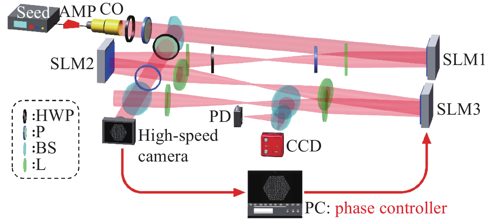
Fig. 1. Experimental schematic
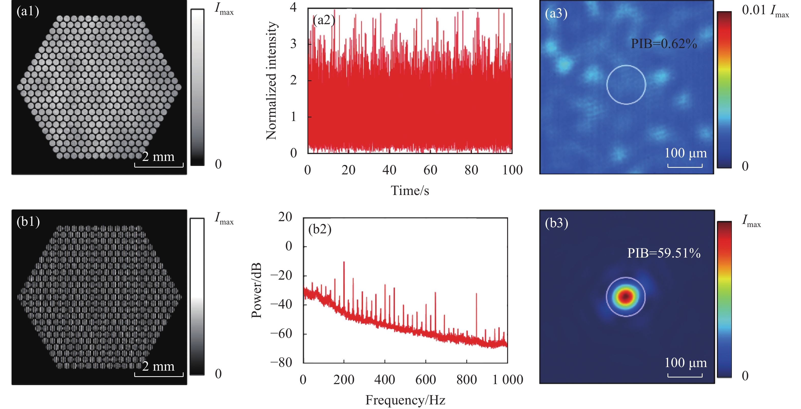
Fig. 2. Experimental results. (a1) The intensity profile of the laser array; (a2) The time-domain distribution of the light intensity inside the pin-hole in the open-loop state; (a3) The zoomed long exposure image in the open-loop state; (b1) The intensity profile of interference fringes; (b2) The spectrogram of light intensity inside the pin-hole in the open-loop state; (b3) The zoomed long exposure image in the close-loop state


Set citation alerts for the article
Please enter your email address

© Copyright 2018-2021 | Chinese Laser Press. All Rights Reserved 沪ICP备15018463号-20