
Xuanke Zeng, Shuiqin Zheng, Yi Cai, Hongyu Wang, Xiaowei Lu, Honggeng Wang, Jingzhen Li, Weixin Xie, Shixiang Xu. Generation and imaging of a tunable ultrafast intensity-rotating optical field with a cycle down to femtosecond region[J]. High Power Laser Science and Engineering, 2020, 8(1): 010000e3
- High Power Laser Science and Engineering
- Vol. 8, Issue 1, 010000e3 (2020)
![The simulation for the evolution of the interference intensity distribution of a tunable UIROF with (a) $l=\pm 1$ and $\unicode[STIX]{x1D6FA}=7.5~\text{Trad}/\text{s}$; (b) $l_{1}=1$, $l_{2}=-3$ and $\unicode[STIX]{x1D6FA}=3.75~\text{Trad}/\text{s}$; (c) $l=\pm 3$ and $\unicode[STIX]{x1D6FA}=7.5~\text{Trad}/\text{s}$.](/richHtml/hpl/2020/8/1/010000e3/img_1.png)
Fig. 1. The simulation for the evolution of the interference intensity distribution of a tunable UIROF with (a) $l=\pm 1$ and $\unicode[STIX]{x1D6FA}=7.5~\text{Trad}/\text{s}$ ; (b) $l_{1}=1$ , $l_{2}=-3$ and $\unicode[STIX]{x1D6FA}=3.75~\text{Trad}/\text{s}$ ; (c) $l=\pm 3$ and $\unicode[STIX]{x1D6FA}=7.5~\text{Trad}/\text{s}$ .
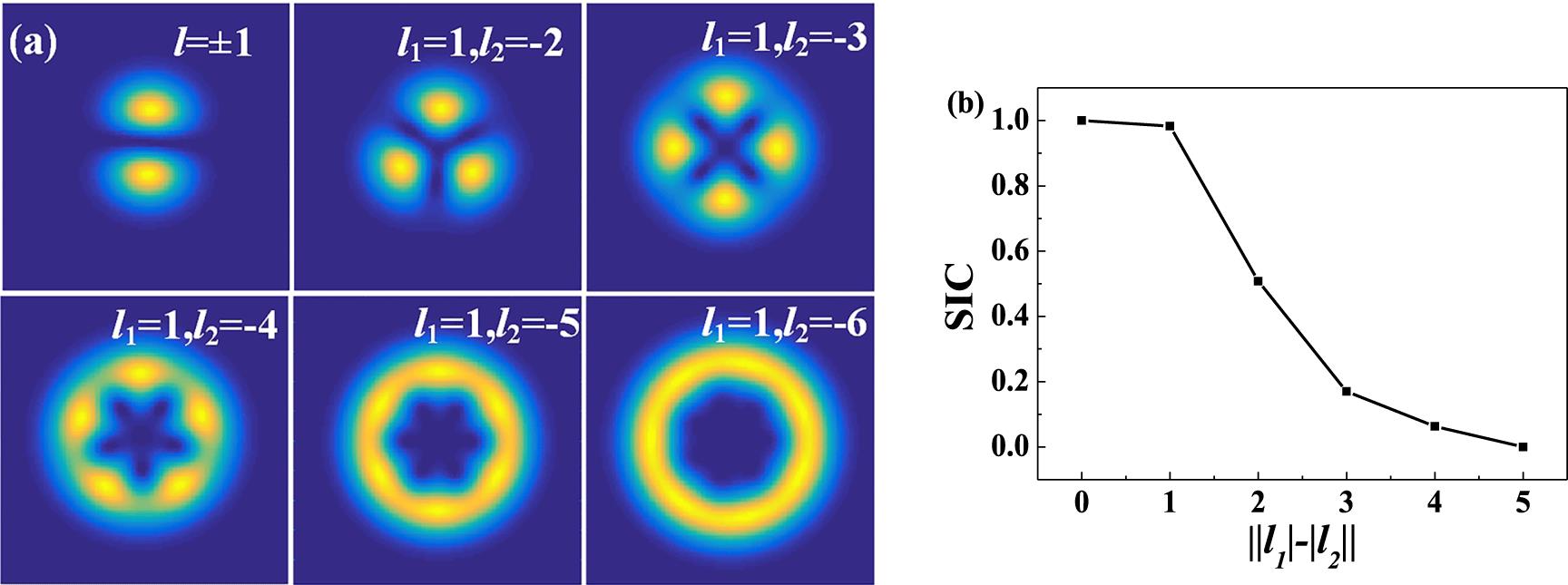
Fig. 2. (a) The pattern of the tunable UIROF with different $\Vert l_{1}|-|l_{2}\Vert$ ; (b) the SIC versus $\Vert l_{1}|-|l_{2}\Vert$ .
Fig. 3. Setup of the tunable UIROF. BS1 and BS2, beam splitters; L, optical lens; M1–M4, mirrors; MI, asymmetrical Michelson interferometer; P, polarizer; PS, pulse stretcher; QWP, quarter-wave plate; SPG, spiral phase generator; TA, target; TDL, time delay line; VHWP, space-variant half-wave plate.
Fig. 4. The rotating angular velocity versus time shift and pulse width when $l=\pm 1$ .
Fig. 5. Setup of single-shot ultrafast imaging for the tunable UIROF by NCOPAs. BS-1–BS-3, beam splitters; CCD-1–CCD-4, charge-coupled devices; COS-1–COS-4, confocal optical systems; M, mirror; NCOPA-1–NCOPA-4, noncollinear optical-parametric amplifiers; OAS, optical attenuation slice; SHG, second-harmonic generator; TDL-1–TDL-4, time delay lines; WS, wavelength separator.
Fig. 6. The instantaneous idler images of the rotating ring lattice by the ultrafast real-time frame NCOPA imaging. (a) $\unicode[STIX]{x1D6FA}=3.95~\text{Trad}/\text{s}$ with the imaging rate of 1.9 Tfps; (b) $\unicode[STIX]{x1D6FA}=11.9~\text{Trad}/\text{s}$ with the imaging rate of 7.5 Tfps; (c) $\unicode[STIX]{x1D6FA}=11.9~\text{Trad}/\text{s}$ with the imaging rate of 15 Tfps.

Set citation alerts for the article
Please enter your email address
© Copyright 2018-2021 | Chinese Laser Press. All Rights Reserved 沪ICP备15018463号-20