• High Power Laser Science and Engineering
  • Vol. 8, Issue 1, 010000e3 (2020)
Xuanke Zeng1、2, Shuiqin Zheng1, Yi Cai1, Hongyu Wang1, Xiaowei Lu1, Honggeng Wang1, Jingzhen Li1, Weixin Xie2, and Shixiang Xu1
Author Affiliations
  • 1Shenzhen Key Laboratory of Micro-Nano Photonic Information Technology, College of Physics and Optoelectronics Engineering, Shenzhen University, Shenzhen518060, China
  • 2College of Electronic and Information Engineering, Shenzhen University, Shenzhen518060, China
  • show less
    DOI: 10.1017/hpl.2020.1 Cite this Article Set citation alerts
    Xuanke Zeng, Shuiqin Zheng, Yi Cai, Hongyu Wang, Xiaowei Lu, Honggeng Wang, Jingzhen Li, Weixin Xie, Shixiang Xu. Generation and imaging of a tunable ultrafast intensity-rotating optical field with a cycle down to femtosecond region[J]. High Power Laser Science and Engineering, 2020, 8(1): 010000e3 Copy Citation Text show less

    Abstract

    A tunable ultrafast intensity-rotating optical field is generated by overlapping a pair of 20 Hz, 800 nm chirped pulses with a Michelson interferometer (MI). Its rotating rate can be up to 10 trillion radians per second ($\text{Trad}/\text{s}$), which can be flexibly tuned with a mirror in the MI. Besides, its fold rotational symmetry structure is also changeable by controlling the difference from the topological charges of the pulse pair. Experimentally, we have successfully developed a two-petal lattice with a tunable rotating speed from $3.9~\text{Trad}/\text{s}$ up to $11.9~\text{Trad}/\text{s}$, which is confirmed by our single-shot ultrafast frame imager based on noncollinear optical-parametric amplification with its highest frame rate of 15 trillion frames per second (Tfps). This work is carried out at a low repetition rate. Therefore, it can be applied at relativistic, even ultrarelativistic, intensities, which usually operate in low repetition rate ultrashort and ultraintense laser systems. We believe that it may have application in laser-plasma-based accelerators, strong terahertz radiations and celestial phenomena.

    1 Introduction

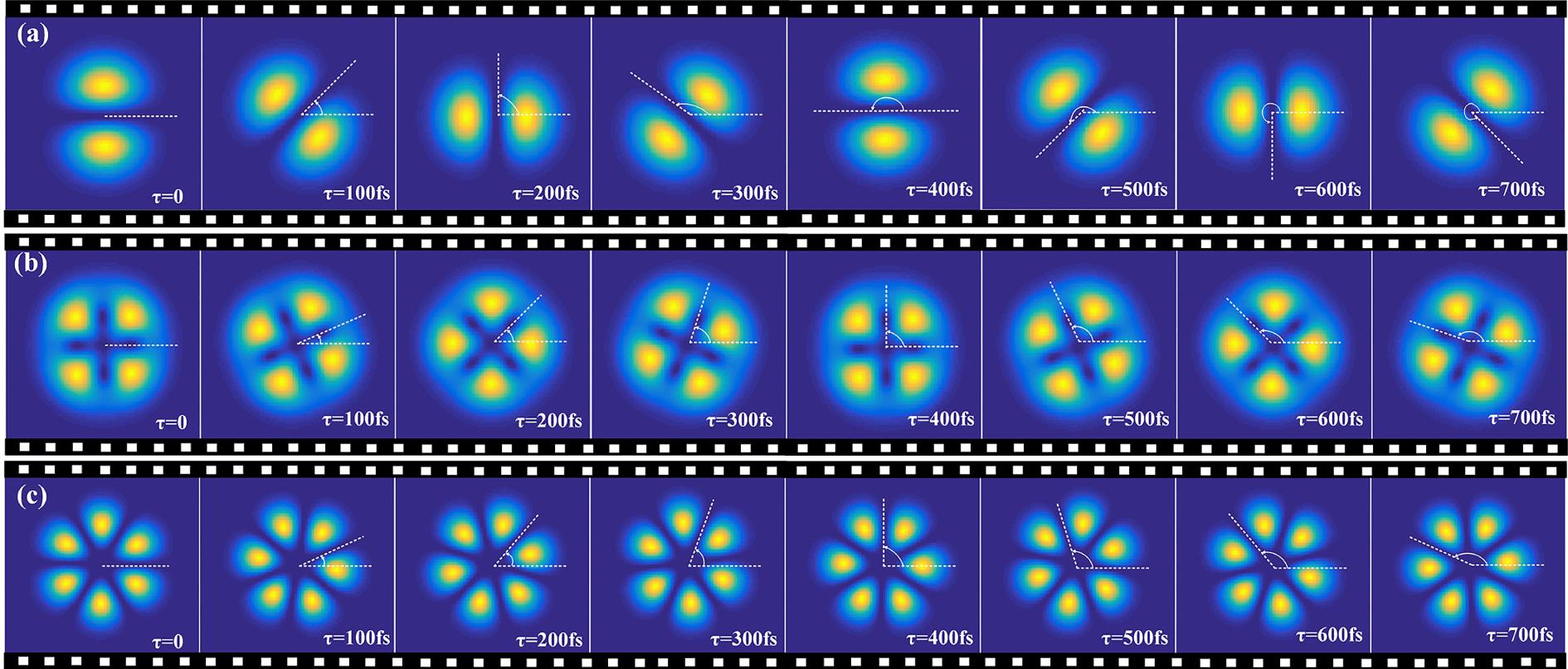
    The ultrafast intensity-rotating optical field (UIROF) has several interesting features. Its spatial structure rotates temporally and depends on the orbital angular momentum (OAM)[13]. Its angular velocity can be regulated by controlling the relative phase difference between two vortex beams. Optical fields have mainly been used in optical manipulations for ultracold atoms and micro-particles[46]. Its application can be expanded to many other areas, especially in intense light–matter interaction[79], if the rotating speed and the intensity of the lattice are boosted into the ultrafast and ultraintense regime. If the optical field can rotate in the terahertz (THz) frequency region at ultraintensity (relativistic intensity, even higher), it may be applied to plasma-based accelerators[1012], intense THz radiations[13, 14], and the evolution process of celestial phenomena in the laboratory[15, 16].

    Several methods have been developed to generate optical fields with their rotating intensities. The fields rotating at the frequency from tens of hertz to hundreds of megahertz have been achieved by using spatial light modulators (SLMs), which can introduce a frequency difference between two vortex beams[46]. The technique of using an electro-optic (EO) modulator together with axially symmetric polarization elements (ASPEs)[17] can increase the rotating speed of an optical field much faster than that with SLMs, but it is still limited to the order of gigahertz due to the restriction from the bandwidth of the EO modulator.

    Here, we present a design to generate a tunable UIROF with tunable ultrafast rotating speed, which results from overlapping two 20 Hz chirped vortex pulses with different topological charges (TCs), $l_{1}$ and $l_{2}$, from a Michelson interferometer (MI). The rotating speed of the UIROF has a higher maximum [11.9 trillion radians per second ($\text{Trad}/\text{s}$)] as well as a larger variable range. By using our single-shot imaging device based on noncollinear optical-parametric amplifications with the highest imaging rate of 15 trillion frames per second (Tfps), we have successfully observed the UIROF. This work is carried out at a low repetition rate, which means that it can be utilized in an ultrashort and ultraintense laser system; so it is applicable in intense laser–material interactions[10].

    2 Principle and numerical simulation of our tunable UIROF

    Our tunable UIROF can be constituted by overlapping two vortex pulses, $E_{1}(r,\unicode[STIX]{x1D703},\unicode[STIX]{x1D714})$ and $E_{2}(r,\unicode[STIX]{x1D703},\unicode[STIX]{x1D714})$, which have different central frequencies ($\unicode[STIX]{x1D714}_{1}$ and $\unicode[STIX]{x1D714}_{2}$) and TCs ($l_{1}$ and $l_{2}$), respectively. Accordingly, our tunable UIROF can be expressed as[12]$$\begin{eqnarray}\displaystyle E(r,\unicode[STIX]{x1D703},\unicode[STIX]{x1D714}) & = & \displaystyle E_{1}(r,\unicode[STIX]{x1D703},\unicode[STIX]{x1D714})+E_{2}(r,\unicode[STIX]{x1D703},\unicode[STIX]{x1D714})\nonumber\\ \displaystyle & = & \displaystyle E_{1}(r,\unicode[STIX]{x1D703})\exp (il_{1}\unicode[STIX]{x1D703})\cdot E_{1}(\unicode[STIX]{x1D714}-\unicode[STIX]{x1D714}_{1})\nonumber\\ \displaystyle & & \displaystyle +\,E_{2}(r,\unicode[STIX]{x1D703})\exp (il_{2}\unicode[STIX]{x1D703})\cdot E_{2}(\unicode[STIX]{x1D714}-\unicode[STIX]{x1D714}_{2}).\end{eqnarray}$$ Here, $E_{1}(r,\unicode[STIX]{x1D703})$ and $E_{2}(r,\unicode[STIX]{x1D703})$ are the space-dependent complex amplitudes, while $E_{1}(\unicode[STIX]{x1D714}-\unicode[STIX]{x1D714}_{1})$ and $E_{2}(\unicode[STIX]{x1D714}-\unicode[STIX]{x1D714}_{2})$ are spectra of the two pulses ($\unicode[STIX]{x1D714}_{2}\geqslant \unicode[STIX]{x1D714}_{1}$). In time domain, the UIROF shall be $$\begin{eqnarray}\displaystyle E(r,\unicode[STIX]{x1D703},t) & = & \displaystyle E_{1}(r,\unicode[STIX]{x1D703})E_{1}(t)\exp (il_{1}\unicode[STIX]{x1D703})\cdot \exp (i\unicode[STIX]{x1D714}_{1}t)\nonumber\\ \displaystyle & & \displaystyle +\,E_{2}(r,\unicode[STIX]{x1D703})E_{2}(t)\exp (il_{2}\unicode[STIX]{x1D703})\cdot \exp (i\unicode[STIX]{x1D714}_{2}t),\end{eqnarray}$$ where $E_{1}(t)$ and $E_{2}(t)$ are the Fourier transforms of $E_{1}(\unicode[STIX]{x1D714})$ and $E_{2}(\unicode[STIX]{x1D714})$, respectively. For singly ringed Laguerre–Gaussian (LG) beams with a TC value of $l$, at $z=0$, $E(r,\unicode[STIX]{x1D703})$ can be expressed as$$\begin{eqnarray}\displaystyle E(r,\unicode[STIX]{x1D703})\,=\,E_{0}^{l}(r,\unicode[STIX]{x1D703})\,=\,\left(\frac{2}{\unicode[STIX]{x1D70B}|l|!}\right)^{\frac{1}{2}}\cdot \frac{1}{w}\left(\frac{r\sqrt{2}}{w}\right)^{|l|}\exp \!\left(\frac{-r^{2}}{w^{2}}\right)\!, & & \displaystyle \nonumber\\ \displaystyle & & \displaystyle\end{eqnarray}$$ where $w$ denotes the beam radius. If $\unicode[STIX]{x1D714}_{0}=(\unicode[STIX]{x1D714}_{1}+\unicode[STIX]{x1D714}_{2})/2$, $\unicode[STIX]{x1D6FF}\unicode[STIX]{x1D714}/2=(\unicode[STIX]{x1D714}_{2}-\unicode[STIX]{x1D714}_{1})/2$ and $E_{1}(r,\unicode[STIX]{x1D703})E_{1}(t)=E_{0}^{l_{1}}(r,\unicode[STIX]{x1D703})E_{1}(t)=E_{l1}$, $E_{2}(r,\unicode[STIX]{x1D703})E_{2}(t)=E_{0}^{l_{2}}(r,\unicode[STIX]{x1D703})E_{2}(t)=E_{l2}$, Equation (2) becomes $$\begin{eqnarray}\displaystyle E(r,\unicode[STIX]{x1D703},t) & = & \displaystyle \left[E_{l_{1}}\exp \left(il_{1}\unicode[STIX]{x1D703}-i\frac{\unicode[STIX]{x1D6FF}\unicode[STIX]{x1D714}}{2}t\right)\right.\nonumber\\ \displaystyle & & \displaystyle +\left.E_{l_{2}}\exp \left(il_{2}\unicode[STIX]{x1D703}+i\frac{\unicode[STIX]{x1D6FF}\unicode[STIX]{x1D714}}{2}t\right)\right]\exp (i\unicode[STIX]{x1D714}_{0}t).\end{eqnarray}$$

    Equation (4) implies that the UIROF is an intensity-rotating field with a velocity $\unicode[STIX]{x1D6FA}=\text{d}\unicode[STIX]{x1D703}/\text{d}t=\unicode[STIX]{x1D6FF}\unicode[STIX]{x1D714}/|l_{1}-l_{2}|$.

    Figure 1 shows our simulations for the evolution of the interference intensity distribution of the UIROF with different TC combinations and $\unicode[STIX]{x1D6FF}\unicode[STIX]{x1D714}$ from $E_{1}(r,\unicode[STIX]{x1D703},\unicode[STIX]{x1D714})$ and $E_{2}(r,\unicode[STIX]{x1D703},\unicode[STIX]{x1D714})$ but $E_{1}(t)=E_{2}(t)$. We get a UIROF with a tunable period from 0.8 ps to 1.6 ps by controlling the parameters $\unicode[STIX]{x1D6FF}\unicode[STIX]{x1D714}$ and $|l_{1}-l_{2}|$. At the beat frequency $\unicode[STIX]{x1D6FF}\unicode[STIX]{x1D714}=15~\text{Trad}/\text{s}$ when $l_{1}=1$ and $l_{2}=-1$ (thus $|l_{1}-l_{2}|=2$), Figure 1(a) shows that the field has a two-petal spatial intensity. Meanwhile, it rotates counterclockwise around its optical axis with a rotation period of about 800 fs or an angular velocity $\unicode[STIX]{x1D6FA}$ of $7.5~\text{Trad}/\text{s}$. $\unicode[STIX]{x1D6FA}$ can be varied by using different TC and $\unicode[STIX]{x1D6FF}\unicode[STIX]{x1D714}$ values for the two vortex beams. Figure 1(b) exhibits a four-petal optical field, where $l_{1}=1$ and $l_{2}=-3$; hence $|l_{1}-l_{2}|=4$. We can see that the field rotates counterclockwise with an angular velocity $\unicode[STIX]{x1D6FA}$ of $3.75~\text{Trad}/\text{s}$, half of that in Figure 1(a), when $\unicode[STIX]{x1D6FF}\unicode[STIX]{x1D714}=15~\text{Trad}/\text{s}$. In Figure 1(c), the field has a six-petal profile when $l_{1}=3$ and $l_{2}=-3$. Correspondingly, $\unicode[STIX]{x1D6FA}$ is equal to that of Figure 1(b) if $\unicode[STIX]{x1D6FF}\unicode[STIX]{x1D714}$ goes up to $22.5~\text{Trad}/\text{s}$. Our calculations reveal that the petal numbers of the spatial profile are equal to $|l_{1}-l_{2}|$, which means that the optical fields with the same $|l_{1}-l_{2}|$ but different values of $l_{1}$ and $l_{2}$ have equal petal numbers. However, the optical field has a higher tangential spatial intensity contrast (SIC) with conjugated TC values than that with $|l_{1}|\neq |l_{2}|$, which is similar to the occurrence of maximal modulation between two identical interfering beams. Here, the tangential SIC is defined as $(I_{\text{max}}-I_{\text{min}})/(I_{\text{max}}+I_{\text{min}})$, where $I_{\text{max}}$ and $I_{\text{min}}$ refer to the maximal and minimal intensities of the UIROF across the petal centers, respectively. Our results also show that $\unicode[STIX]{x1D6FA}$ is proportional to $\unicode[STIX]{x1D6FF}\unicode[STIX]{x1D714}$ but inversely proportional to $|l_{1}-l_{2}|$; $\unicode[STIX]{x1D6FA}|l_{1}-l_{2}|$ is constant for a given $\unicode[STIX]{x1D6FF}\unicode[STIX]{x1D714}$. The patterns of the UIROF with different $\Vert l_{1}|-|l_{2}\Vert$ are shown in Figure 2(a); we can see the clearest separation between the two petals when $l_{1}=1$ and $l_{2}=-1$. If $l_{1}$ is kept constant, the separations among the petals blur gradually when $l_{2}$ changes from $-1$ to $-6$. Figure 2(b) presents our calculated result, where SIC decreases monotonously with $\Vert l_{1}|-|l_{2}\Vert$. This can be explained by spatial intensity matching. When $|l_{1}|=|l_{2}|$, the two beams have perfect spatial intensity matching, which will diminish with an increase in $\Vert l_{1}|-|l_{2}\Vert$. This means that the UIROF has the same rotating angular velocity but different SIC for the same $|l_{1}-l_{2}|$ and different $\Vert l_{1}|-|l_{2}\Vert$.

    3 Experimental arrangement and results

    We realize experimentally our tunable UIROF as shown in Figure 3. A linearly polarized femtosecond pulse is seeded into a pulse stretcher (PS); thus it becomes a chirped pulse. A spiral phase generator (SPG) is used to modulate and convert the chirped pulse into a vortex pulse, which includes two quarter-wave plates and a vortex half-wave retarder ($q$-plate, VHWR). A polarizer (P) is placed after the SPG to keep the vortex pulse linearly polarized. In order to generate a pair of vortex pulses, the pulse then passes through an MI, where there are three mirrors (M1–M3) in one arm and two mirrors [working as the time delay line (TDL)] in the other one. This asymmetrical design allows the two output pulses from the MI to have conjugated TC values of $\pm l$ but with the same spatial amplitude profile. Different values of $l$ can be realized by using VHWRs of different orders.

    In our design, the beat frequency shall be $$\begin{eqnarray}\unicode[STIX]{x1D6FF}\unicode[STIX]{x1D714}=\unicode[STIX]{x1D714}(t)-\unicode[STIX]{x1D714}(t-\unicode[STIX]{x1D6FF}t)=C\unicode[STIX]{x1D6FF}t,\end{eqnarray}$$ where $\unicode[STIX]{x1D6FF}t$ is the time delay between the two chirped vortex pulses and $C$ is the chirp coefficient, which can be estimated as $$\begin{eqnarray}C\approx 2a\sqrt{\frac{\unicode[STIX]{x1D70F}^{2}}{\unicode[STIX]{x1D70F}_{0}^{2}}-1}.\end{eqnarray}$$ Here, $a=2\ln (2)/\unicode[STIX]{x1D70F}^{2}$, depending on the chirped pulse duration $\unicode[STIX]{x1D70F}$, which stretches from a transform-limited pulse with a duration of $\unicode[STIX]{x1D70F}_{0}$. Accordingly, the rotating period of the tunable UIROF is given by $$\begin{eqnarray}T=\frac{2\unicode[STIX]{x1D70B}|l_{1}-l_{2}|}{\unicode[STIX]{x1D6FF}\unicode[STIX]{x1D714}}=\frac{2\unicode[STIX]{x1D70B}|l_{1}-l_{2}|}{C\unicode[STIX]{x1D6FF}t},\end{eqnarray}$$ and $\unicode[STIX]{x1D6FA}$ can be rewritten as $$\begin{eqnarray}\unicode[STIX]{x1D6FA}=\frac{C\unicode[STIX]{x1D6FF}t}{|l_{1}-l_{2}|}.\end{eqnarray}$$

    We can see that the rotating period $T$ or angular velocity $\unicode[STIX]{x1D6FA}$ depends on three parameters: $\unicode[STIX]{x1D70F}$, $\unicode[STIX]{x1D6FF}t$ and $|l_{1}-l_{2}|$. $\unicode[STIX]{x1D6FA}$ is proportional to $\unicode[STIX]{x1D6FF}t$ but inversely proportional to $\unicode[STIX]{x1D70F}$ and $|l_{1}-l_{2}|$. Therefore, we can tune $\unicode[STIX]{x1D6FA}$ by adjusting $\unicode[STIX]{x1D70F}$ and $\unicode[STIX]{x1D6FF}t$ through controlling optical dispersion and relative time delay between the two pulses. As shown in Figure 4, the blue curve shows the rotating angular velocity versus time shift $\unicode[STIX]{x1D6FF}t$ with a chirped pulse duration $\unicode[STIX]{x1D70F}$ of 3 ps, whereas the red curve shows the angular velocity versus $\unicode[STIX]{x1D70F}$ with $\unicode[STIX]{x1D6FF}t=0.6~\text{ps}$ when $l_{1}=+1$ and $l_{2}=-1$. One can see that the rotating angular velocity increases linearly with $\unicode[STIX]{x1D6FF}t$ and decreases parabolically with $\unicode[STIX]{x1D70F}$. The angular velocity increases from $1.32~\text{Trad}/\text{s}$ to $19.8~\text{Trad}/\text{s}$ with $\unicode[STIX]{x1D6FF}t$ from 0.1 ps to 1.5 ps when $\unicode[STIX]{x1D70F}$ is 3 ps, and it changes from $23.75~\text{Trad}/\text{s}$ to $3.96~\text{Trad}/\text{s}$ from 1 ps to 6 ps for $\unicode[STIX]{x1D6FF}t=0.6~\text{ps}$. This means that our device can easily attain a tunable angular velocity up to several $\text{Trad}/\text{s}$ even up to $10~\text{Trad}/\text{s}$. Besides, the angular velocity is inversely proportional to $|l_{1}-l_{2}|$ or decreases with the number of petals in UIROF.

    In our experiment, a commercial 20 Hz, 35 fs, 800 nm Ti:S laser system with a pulse energy of 3.5 mJ is used to generate tunable UIROF at a low repetition rate and strong intensity. One can note that because we can accurately control the chirped pulse width $\unicode[STIX]{x1D70F}$ and the time shift $\unicode[STIX]{x1D6FF}t$ with a precision of the order of femtosecond in the setup, the angular frequency difference $\unicode[STIX]{x1D6FF}\unicode[STIX]{x1D714}$ introduced by the UIROF can reach the order of tens of THz or even higher easily according to Equations (5)–(8). Therefore, it allows us to obtain an intensity-rotating optical field with a tunable rotating frequency of tens of THz, which is much faster than previous methods such as SLMs[5] and ASPEs[17]. As the optical field rotates with such a high angular velocity at a low repetition rate, a single-shot ultrafast real-time frame imaging device instead of femtosecond pump–probe techniques[18] is required for accurate observation. However, it is difficult for existing single-shot imaging technologies[1924] to achieve high spatial and temporal resolution simultaneously at such a high imaging rate. Besides, about 70% pulse energy (${\sim}2.4~\text{mJ}$) is used to generate the UIROF with a tunable rotating intensity after an optical attenuation slice (OAS). The maximum peak intensity can be up to $2\times 10^{9}~\text{W}/\text{cm}^{2}$ at a beam diameter of 10 mm. If focused to a beam diameter of $100~\unicode[STIX]{x03BC}\text{m}$, it can be raised to $2\times 10^{13}~\text{W}/\text{cm}^{2}$. If focused further, a higher intensity is available.

    Under these circumstances, an ultrafast single-shot imaging device with an imaging rate beyond 10 Tfps is designed by noncollinear optical-parametric amplifiers (NCOPAs) to obtain the rotating characteristic of the tunable UIROF. As is known, an optical-parametric amplifier (OPA) can map the signal information into an idler beam with high spatial resolution[25, 26]. Meanwhile, using ultrashort pulses as the pump beam for the OPA makes the idler beam an ultrafast optical shutter. Therefore, our NCOPAs form a single-shot imaging device with both high spatial and temporal resolution. The device diagram is shown in Figure 5. The output of the femtosecond laser first passes through a second-harmonic generator, a 0.2-mm and $29.2^{\circ }$-cut $\unicode[STIX]{x03B2}$-BBO crystal. About 30% of the laser pulse is converted into its second harmonic (400 nm pulse). The unconverted 800 nm fundamental pulse is reflected and incident on the setup (see Figure 1) to generate the tunable UIROF after an OAS. The optical field emerging from the setup then works as the signal. The 400 nm femtosecond pulse is split into four sub-pulses by three 50:50 beam splitters (BS1–BS3) as the pump beams for the four NCOPAs (1–4) with different time delays (TDL-1–TDL-4). Four pieces of 0.5-mm-thick $29.2^{\circ }$-cut $\unicode[STIX]{x03B2}$-BBO crystals operate in OPAs under type-I phase matching. In every amplifier, the pump and the signal are arranged at a small intersection angle (${\sim}2^{\circ }$) inside the $\unicode[STIX]{x03B2}$-BBO crystals for the generated idler to deviate spatially from both of them. In each amplifier, the delay time between the pump and the signal can be adjusted independently with TDL-1–TDL-4. Hence the idler beams are spatially separated from the signal and pump beams due to momentum conversion and can be recorded by different charge-coupled device (CCD) cameras (CCD-1–CCD-4). After a 0-moment synchronous calibration, information at four different times of the rotating ring-shaped beam can be recorded from the four idler beams just by adjusting TDL-1–TDL-4 of the NCOPAs.

    Here, we get experimentally a UIROF with an angular velocity of $10~\text{Trad}/\text{s}$. The pulse duration $\unicode[STIX]{x1D70F}$ is broadened from 35 fs to 3 ps by a PS, which consists of a pair of prisms. The central angular frequency of the chirped pulse is $2.36\times 10^{15}~\text{rad}/\text{s}$, and the time shift $\unicode[STIX]{x1D6FF}t$ of the two interfering vortex beams with $l_{1}=1$ and $l_{2}=-1$ can be controlled and adjusted by the TDL in Figure 3. After tuning the time synchronization between the signal (the UIROF) and the four pump beams, respectively, by TDL-1–TDL-4 successively in Figure 5, four idler images, which can describe the evolution of the UIROF with time, are shown in Figure 6(a) by our setup for single-shot ultrafast imaging. First, we set $\unicode[STIX]{x1D6FF}t=0.3~\text{ps}$; so the angular frequency difference $\unicode[STIX]{x1D6FF}\unicode[STIX]{x1D714}$ of the two vortex pulses is ${\sim}7.9~\text{Trad}/\text{s}$, and the imaging frame time intervals $\unicode[STIX]{x0394}t=533~\text{fs}$ after a 0-moment calibration of the four idler images. Therefore, four instantaneous idler images of the tunable UIROF at the frame rate of 1.9 Tfps ($t=0$, 533 fs, 1.07 ps and 1.6 ps) were recorded by the four CCD cameras. One can see that the UIROF has two petals because of the two interfering vortex beams with TCs $\pm 1$, separately. As expected, the UIROF continuously rotates counterclockwise for a period of 1 ps, and the angular velocity $\unicode[STIX]{x1D6FA}$ is equal to $2\unicode[STIX]{x1D70B}~\text{rad}/1.6~\text{ps}\approx 3.9~\text{Trad}/\text{s}$, which is close to the theoretical value ($0.5\times 7.9~\text{Trad}/\text{s}=3.95~\text{Trad}/\text{s}$) calculated by Equation (7). By tuning TDL to change the time shift $\unicode[STIX]{x1D6FF}t$ to 0.9 ps, the UIROF has an angular frequency difference $\unicode[STIX]{x1D6FF}\unicode[STIX]{x1D714}$ of ${\sim}23.8~\text{Trad}/\text{s}$. In Figure 6(b), four instantaneous idler images at the frame rate of 7.5 Tfps ($t=0$, 133 fs, 266 fs and 400 fs) are obtained by regulating the relative pump delays $\unicode[STIX]{x0394}t$ of the four NCOPAs to 133 fs in turn. The optical field rotates at an angle of $2\unicode[STIX]{x1D70B}\times 3/4~\text{rad}$ within 400 fs; so the maximum angular velocity $\unicode[STIX]{x1D6FA}$ is $11.8~\text{Trad}/\text{s}$. We tune the frame interval $\unicode[STIX]{x0394}t$ to be shorter so that the frame rate increases to 15 Tfps of the NCOPAs, correspondingly. Four instantaneous idler images with a ${\sim}66.7~\text{fs}$ interval are shown in Figure 6(c). The optical field rotates at an angle of about $0.9\unicode[STIX]{x1D70B}~\text{rad}$ within 200 fs so that the $\unicode[STIX]{x1D6FA}$ value is $11.8~\text{Trad}/\text{s}$, which is close to the theoretical value of $11.9~\text{Trad}/\text{s}$.

    4 Conclusions

    In summary, a tunable UIROF at 20 Hz with a tunable rotating speed beyond $10~\text{Trad}/\text{s}$ is generated by overlapping a pair of chirped vortex pulses with an asymmetrical MI. The frequency difference between the two vortex beams can be tuned accurately by a TDL in an MI with an accuracy of tens of femtoseconds, which allows us to adjust and control precisely the rotation period of the ring-shaped rotating field in the ultrafast regime. We get experimentally a 20-Hz two-petal UIROF, which has a tunable rotating speed from 3.9 to $11.9~\text{Trad}/\text{s}$. By using our single-shot imaging device based on noncollinear optical-parametric amplification with the highest imaging rate of 15 Tfps, we have successfully observed the tunable UIROF. As expected, the instantaneous images of the evolution of the tunable UIROF with time agree with the theoretical calculation. The tunable UIROF has potential applications in some fields, for instance, ultrafast–ultraintense physics, plasma-based accelerators, radiations of strong THz and simulations and experiments for the evolution process of celestial phenomena in the laboratory.

    References

    [1] Q. Xiao, C. Klitis, S. Li, Y. Chen, X. Cai, M. Sorel, S. Yu. Opt. Express, 24, 3168(2016).

    [2] L. Amico, A. Osterloh, F. Cataliotti. Phys. Rev. Lett., 95, 063201(2005).

    [3] C. J. Schmitz, K. Uhrig, J. P. Spatz, J. E. Curtis. Opt. Express, 14, 6604(2006).

    [4] M. P. MacDonald, L. Paterson, K. Volke-Sepulveda, J. Arlt, W. Sibbett, K. Dholakia. Science, 296, 1101(2002).

    [5] S. Franke-Aenold, J. Leach, M. J. Padgett, V. E. Lembessis, D. Ellinas, A. J. Wright, J. M. Girkin, P. Ohberg, A. S. Arnold. Opt. Express, 15, 8619(2007).

    [6] R. Campbell, G. L. Oppo. Phys. Rev. A, 94, 043626(2016).

    [7] R. Geneaux, A. Camper, T. Auguste, O. Gobert, J. Caillat, R. Taieb, T. Ruchon. Nat. Commun., 7, 12583(2016).

    [8] E. Hemsing, M. Dunning, D. Xiang, A. Marinelli, C. Hast. Nat. Phys., 9, 549(2013).

    [9] Y. Shi, B. Shen, L. Zhang, X. Zhang, W. Wang, Z. Xu. Phys. Rev. Lett., 112, 235001(2014).

    [10] J. Vieira, J. T. Mendonca. Phys. Rev. Lett., 112, 215001(2014).

    [11] J. Vieira, R. M. G. M. Trines, E. P. Alves, R. A. Fonseca, J. T. Mendonca, R. Bingham, P. Norreys, L. O. Silva. Nat. Commun., 7, 10371(2016).

    [12] Y. Shi, J. Vieira, R. M. G. M. Trines, R. Bingham, B. F. Shen, R. J. Kingham. Phys. Rev. Lett., 121, 145002(2018).

    [13] E. Nanni, W. Huang, K. Hong, K. Ravi, A. Fallahi, G. Moriena, R. D. Miller, F. Kartner. Nat. Commun., 6, 8486(2015).

    [14] S. Dhillon. J. Phys. D: Appl. Phys., 50, 043001(2017).

    [15] F. Tamburini, B. Thide, G. Molina-Terriza, G. Anzolin. Nat. Phys., 7, 195(2011).

    [16] B. Albertazzi, A. Ciardi, M. Nakatsutsumi, T. Vinci, J. Béard, R. Bonito, J. Billette, M. Borghesi, Z. Burkley, S. N. Chen, T. E. Cowan, T. Herrmannsdörfer, D. P. Higginson, F. Kroll, S. A. Pikuz, K. Naughton, L. Romagnani, C. Riconda, G. Revet, R. Riquier, H.-P. Schlenvoigt, I. Yu. Skobelev, A.Ya. Faenov, A. Soloviev, M. Huarte-Espinosa, A. Frank, O. Portugall, H. Pépin, J. Fuchs. Science, 346, 325(2014).

    [17] M. Sakamoto, K. Oka, R. Morita, N. Murakami. Opt. Lett., 38, 3661(2013).

    [18] M. Domke, S. Rapp, M. Schmidt, H. P. Huber. Opt. Express, 20, 10330(2012).

    [19] K. Goda, K. Tsia, B. Jalali. Nature, 485, 1145(2009).

    [20] L. Gao, J. Liang, C. Li, L. V. Wang. Nature, 516, 74(2014).

    [21] Z. Li, R. Zgadzaj, X. Wang, Y. Chang, M. Downer. Nat. Commun., 5, 3085(2014).

    [22] K. Nakagawa, A. Iwasaki, Y. Oishi, R. Horisaki, A. Tsukamoto, A. Nakamura, K. Hirosawa, H. Liao, T. Ushida, K. Goda, F. Kannari, I. Sakuma. Nat. Photon., 8, 695(2014).

    [23] A. Ehn, J. Bood, Z. Li, E. Berrocal, M. Alden, E. Kristensson. Light Sci. Appl., 6, E17045(2017).

    [24] J. Liang, L. V. Wang. Optica, 5, 1113(2018).

    [25] X. Zeng, Y. Cai, W. Chen, S. Zheng, J. Li, T. Zhu, S. Xu. IEEE Photon. J., 7, 6804107(2015).

    [26] P. M. Vaughan, R. Trebino. Opt. Express, 19, 8920(2011).

    Xuanke Zeng, Shuiqin Zheng, Yi Cai, Hongyu Wang, Xiaowei Lu, Honggeng Wang, Jingzhen Li, Weixin Xie, Shixiang Xu. Generation and imaging of a tunable ultrafast intensity-rotating optical field with a cycle down to femtosecond region[J]. High Power Laser Science and Engineering, 2020, 8(1): 010000e3
    Download Citation