V. D. Zvorykin, I. G. Lebo, A. V. Shutov, N. N. Ustinovskii. Self-focusing of UV radiation in 1 mm scale plasma in a deep ablative crater produced by 100 ns, 1 GW KrF laser pulse in the context of ICF[J]. Matter and Radiation at Extremes, 2020, 5(3): 035401
Copy Citation Text
Experiments at the GARPUN KrF laser facility and 2D simulations using the NUTCY code were performed to study the irradiation of metal and polymethyl methacrylate (PMMA) targets by 100 ns UV pulses at intensities up to 5 × 10¹² W cm-2. In both targets, a deep crater of length 1 mm was produced owing to the 2D geometry of the supersonic propagation of the ablation front in condensed matter that was pushed sideways by a conical shock wave. Small-scale filamentation of the laser beam caused by thermal self-focusing of radiation in the crater-confined plasma was evidenced by the presence of a microcrater relief on the bottom of the main crater. In translucent PMMA, with a penetration depth for UV light of several hundred micrometers, a long narrow channel of length 1 mm and diameter 30 μm was observed emerging from the crater vertex. Similar channels with a length-to-diameter aspect ratio of ~1000 were produced by a repeated-pulse KrF laser in PMMA and fused silica glass at an intensity of ~109 W cm-2. This channel formation is attributed to the effects of radiation self-focusing in the plasma and Kerr self-focusing in a partially transparent target material after shallow-angle reflection by the crater wall. Experimental modeling of the initial stage of inertial confinement fusion-scale direct-drive KrF laser interaction with subcritical coronal plasmas from spherical and cone-type targets using crater-confined plasmas seems to be feasible with increased laser intensity above 1014 W cm-2.
I. INTRODUCTION
Much effort is being expended worldwide on the creation of huge laser installations such as the National Ignition Facility (NIF) in the USA,1 Laser Megajoule (LMJ) in France,2 Shen Guang (SG III and IV)3,4 in China, and UFL-2M in Russia,5 with radiation energies over 2 MJ for implementation of controlled thermonuclear reactions on irradiation of spherical shell microtargets containing D–T fuel. However, laser-driven experiments on ignition of inertial confinement fusion (ICF) performed at the only fully operating NIF facility adopting the indirect-drive scheme with conversion of laser light into x-rays have not yet succeeded in achieving a useful energy gain (the ratio of output thermonuclear energy to laser energy) GT ≥ 1 in a target. Correspondingly, only rather low neutron and alpha particle yields ∼1016 have been obtained,6,7 although there has been some progress in achieving ignition conditions.8 On absorption in the compressed target core, alpha particles with 3.5 MeV energy should sustain fuel burning, whereas 14 MeV neutrons would mostly lead to energy release in the form of a microexplosion. In future ICF power plants, neutrons would have to release their energy in the reactor chamber blanket, thus producing inertial fusion energy (IFE).9 Another concept for generating IFE is the hybrid fusion–fission reactor, in which amplification of ICF explosion energy in a blanket of fissile material10‒13 allows a low target gain. For the direct-drive ICF neutron source in such a hybrid reactor with a bilateral conical target and a neutron yield of 1016–1017, it has been proposed to use a 1 MJ KrF laser driver with long pulses of 100–250 ns14 or a 1 MJ Nd-glass laser (second and third harmonics) with pulses of 10–20 ns.15,16
A drawback of the NIF ignition campaign is that underestimation of hydrodynamic instabilities during target implosion could result in mixing of fuel with shell material before collapse occurs. In addition, conversion of laser radiation into x-rays in a cylindrical hohlraum surrounding a target is excessively lossy.16 An energetically more efficient approach is simultaneous direct-drive target irradiation by hundreds of laser beams (see, e.g., Refs. 16 and 17). However, in that case, the risk of development of instabilities increases because of the poorer uniformity of the light incident on the target. Various beam-smoothing techniques are currently used to reduce the speckling of the coherent light, and laser pulse temporal shaping and appropriate target designs with a low aspect ratio (target radius to shell thickness) decrease the growth rate of instabilities and favor a robust target compression.
However, in a subcritical coronal plasma with electron density ne/ncr < 1, in the vicinity of the critical electron density ncr (cm−3) ≈ 1.115 × 10²¹/λ2, where λ (μm) is the laser wavelength, there are three types of three-wave nonlinear processes that are collectively referred to as laser–plasma parametric instability (LPI).17‒19 Stimulated Brillouin scattering (SBS) and stimulated Raman scattering (SRS) are responsible for backward reflection of incident radiation. SBS also initiates cross-beam energy transfer (CBET) between laser beams, which disrupts implosion symmetry. Fast or suprathermal electrons are generated via two-plasmon decay (TPD) and SRS. Having a kinetic energy significantly higher than the temperature of bulk electrons in the plasma, they penetrate deep into the compressed target core before the collapse and reduce the density that can be achieved. In addition to LPI, self-focusing of a laser beam in a plasma proceeding via ponderomotive or thermal mechanisms could produce light filaments with increased intensity, which would intensify three-wave parametric processes.
The LPI convective gain in an inhomogeneous plasma, is proportional to the laser intensity I, laser wavelength λ, and plasma scale length Ln ≡ ne/|∇ne| and inversely proportional to the electron temperature Te. The instability threshold is then defined as G > 1. Higher LPI thresholds for shorter wavelengths allow higher target irradiation intensities. For a commonly assumed mechanism of inverse bremsstrahlung absorption and short radiation wavelengths, electrons oscillating in the laser field dissipate their energy in collisions more efficiently in a denser plasma. Also, energy transfer by electron conductivity to the ablation front (AF) is more effective, and the ablation pressure is correspondingly higher. These circumstances have pushed the laser wavelength in modern ICF research into the UV spectral range, for example, at the above-mentioned frequency-tripled (3ω) Nd-glass facilities or their competitor, the electron-beam (e-beam)-pumped KrF laser.
The KrF laser fundamentally generates UV light at λ = 0.25 μm and possesses a number of attractive features. A wide bandwidth of ∼3 THz and a short gain recovery time of the gain medium of ∼2 ns allow temporal profiling of laser pulses with a powerful final spike, which is required for the most attractive shock-ignition (SI) ICF approach.20,21 At the 56-beam 3 kJ Nike facility in an induced spatial incoherence (ISI) pulse amplification layout,22,23 the short wavelength and the highest ever uniformity achieved with planar target irradiation ensured mitigation of LPI and robust target compression. CBET can be reduced by optical zooming—a sequential reduction in the size of the irradiation spot on a target, as has already been demonstrated.23,24 A high target gain Gr > 100 at rather low laser energy 500 kJ was simulated for the SI ICF layout.21 A KrF laser amplifier with e-beam pumping could be scaled up to several tens of kilojoules with a wall-plug efficiency of around 7%. As an IFE driver, the laser should operate in 5 Hz repetition-rate mode, which is achievable with working-gas recirculation across the KrF laser chamber.23 The current status of research on both KrF laser physics and laser–target interaction has led to the suggestion of a fusion test facility (FTF) as a viable prototype of an IFE power plant.21,25
The typical plasma length of ∼1 mm that is characteristic of ICF-scale experiments is difficult to reproduce in LPI modeling experiments, since rather high laser energy is needed to irradiate planar targets in a large spot comparable to the plasma length. In early experiments on the 3ω Nd-glass Nova laser with an interaction energy of 1 kJ, exploding thin (∼3 μm) CH film targets were irradiated with 4 ns pulses at an intensity I ∼ 1013 W cm−2 on a 1 mm spot.26 More recently, the 3ω Nd-glass OMEGA EP laser was used at up to 9 kJ in 2.5 ns pulses for irradiation of CH film (30 μm) with I ∼ 1014 W cm−2 on a 1 mm spot.27
In the present paper, we consider the previously poorly studied interaction regime of 100 J, 100 ns KrF laser pulses with planar targets28,29 at intensities up to 5 × 10¹² W cm−2 on a spot of ∼150 μm, when an ablative crater of ∼1 mm depth is formed and confines the lateral expansion of plasma. It is difficult to explore this regime with the commonly used 3ω Nd-glass lasers because of the low conversion efficiency in the tripling crystals for long pulse lengths. The purpose of this research is to study the development of UV radiation self-focusing in extended plasmas, as well as Kerr self-focusing in translucent target materials. We believe that this rather unusual laser ablation regime, besides its relevance to warm dense matter, might be interesting for modeling of the initial stage of a stepwise UV laser pulse interaction with ICF-scale plasmas (known as “foot physics”),21 which occurs at a relatively low intensity of ∼1013 W cm−2. Homogeneity of the plasma corona and uniformity of the ablative pressure directed inward on a spherical shell of D–T fuel play the primary roles in achieving ignition conditions under target collapse. To the best of our knowledge, the effects of Kerr self-focusing of the incident radiation in a plastic ablator or D–T ice have been never previously considered in target implosion experiments and simulations.
II. EXPERIMENTS
A. Operating modes of GARPUN KrF laser
The main module of the large-aperture e-beam-pumped GARPUN KrF laser was constructed in 1991 and produced 100 J, 100 ns pulses in oscillator mode with optimal plane or unstable resonators.30 The installation was later configured into other operating modes:
with injection of narrowband (or a broadband) radiation from a discharge-pumped KrF master oscillator into the unstable resonator of the main large-aperture GARPUN amplifier to control output beam divergence and spectral width, giving 100 J, 100 ns pulses of trapezoidal temporal shape (∼1 GW power);31
a subsequent double-pass amplification of 20 ns pulses of the master oscillator in the e-beam-pumped Berdysh and GARPUN amplifiers, giving 30 J, 20 ns pulses (∼1.5 GW peak power);32
amplification of subpicosecond pulses of a frequency-tripled Ti:sapphire front end in both amplifiers up to 0.6 J and ≤1 ps (∼1 TW);33
amplification of several multiplexed subpicosecond pulses, giving a short-pulse train separated by 3–5 ns time intervals, with output energy up to 2 J;34 and
simultaneous amplification of a subpicosecond pulse train up to 0.2–0.3 TW peak power in each pulse superimposed with a 30 J, 100 ns long pulse.35
A short-pulse version of the installation upgraded in 2007 with a Ti: sapphire front-end was renamed GARPUN-MTW.32
B. GARPUN KrF laser in injection-controlled operation
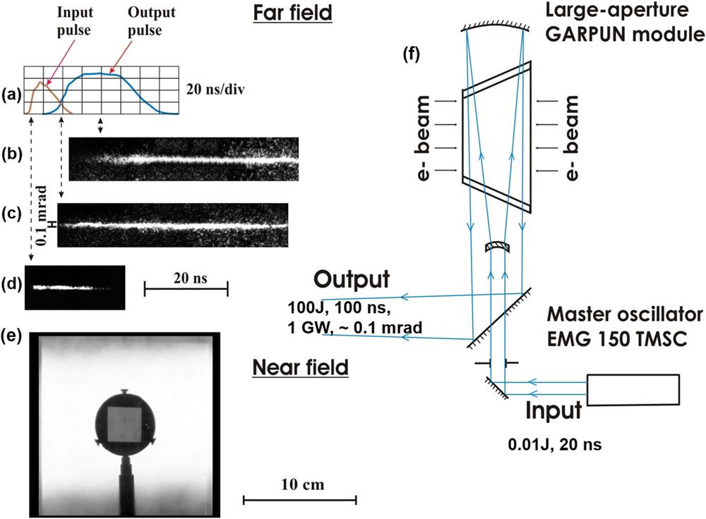
A large-aperture GARPUN amplifier with gain volume of 16 × 18 × 100 cm3 was transversely pumped by two counterpropagating e-beams with electron energy 350 keV, total e-beam current density 50 A cm−2, pulse length ∼100 ns, and specific pumping power Wb = 0.7–0.8 MW cm−3 of the working-gas mixture Ar/Kr/F2 at 1.4 atm pressure (for details, see Refs. 28 and 36). In free-running operation, i.e., without any injection and with an optimally unstable resonator with magnification parameter M = 6, the laser produced 100 ns pulses of energy up to 100 J [Fig. 1(a)] with a rather uniform near-field distribution over ∼250 cm2[Fig. 1(e)]. The spectral width of the output radiation (FWHM) was Δῠ ≈ 40 cm−1 (Δν ≈ 1.3 THz). In the experiments, we measured both time-resolved and time-integrated angular distributions of laser radiation. The time-resolved angular distribution of laser radiation in the far field was obtained by temporally scanning the focal spot with a streak camera [Figs. 1(b)–1(d)]. In these measurements, the output radiation was highly attenuated and focused by an F = 8 m lens. In the free-running mode, the angular distribution narrowed over time, since it evolved from amplified spontaneous emission (ASE). Several round trips through the resonator with 17 ns per trip were required to form a central lobe of the distribution with ∼0.8 × 10⁻⁴ rad at FWHM. This occurred just at the middle of the 100 ns laser pulse [cf. Figs. 1(a) and 1(b)].
Figure 1.Injection-controlled GARPUN operation. (a) Input and output laser pulses (not to scale). (b)–(d) Streak camera images of far-field output radiation: (b) without injection; (c) with injection; (d) of the injected radiation passed through the resonator without amplification. (e) Near-field distribution of input energy. (f) Injection-controlled layout.
In the injection-controlled layout [Fig. 1(f)], narrowband radiation (Δῠ ≈ 0.1 cm−1) from a commercial discharge-pumped laser (Lambda Physik EMG 150 TMSC, 200 mJ and 20 ns) was injected at the beginning of e-beam pumping into the resonator cavity of the GARPUN amplifier through the meniscus [cf. Figs. 1(a) and 1(c)]. As the meniscus focus coincided with the focus of a partially transparent (10%–20%) mirror coated on its convex side, the injected radiation was matched with a diverging wave in the resonator. Thus, the low-energy seed radiation imposed both an angular distribution of output radiation that was steady along the 100 ns pulse [Fig. 1(c)] and a narrow bandwidth Δῠ ≈ 0.1 cm−1. The bandwidth could easily be tuned to a broadband one with Δῠ ≈ 40 cm−1 simply by blocking in the discharge-pumped master oscillator the passage of the injection from the narrowband oscillator to the regenerative amplifier.
To obtain the time-integrated angular distribution over the laser pulse, a K8 glass plate (K8 is an analog of Schott Glass BK7), which absorbed 248 nm radiation, was placed in the focal plane of the F = 2 m lens. Fluorescence of the glass in the blue–green spectral region was imaged by an objective onto a Spiricon SP620U CCD beam profilometer (Ophir Photonics) [Fig. 2(a)]. Compared with direct measurements,37 this technique allows a large dynamic range with no danger of damage to the profilometer. As can be seen, the fluorescence has a rather smooth Gaussian-like distribution with an FWHM of ∼0.8 × 10⁻⁴ rad. Assuming a similar power law for the fluorescence output as a function of laser energy density to that for a picosecond pulse in Ref. 37, namely, f ∝ ε0.4, the laser beam divergence at FWHM was found to be 5 × 10⁻⁵ rad. Note that the slight modulation of the profiles along the x and y axes in Fig. 2(a) is an artifact caused by the finite size of the pixels in the profilometer CCD matrix.
Figure 2.Time-integrated far-field distribution of laser radiation in injection-controlled GARPUN operation: (a) K8 glass fluorescence under irradiation; (b) angular distribution together with energy fraction in a given angle.
To find out how much energy was contained in the central part of the angular distribution, the latter was measured within a dynamic range of ∼104 obtained by attenuating the incident radiation with a set of highly reflective mirrors with a residual transmittance of 1%–2%. A wedge formed by a pair of mirrors with transmittance 50% per round trip was set behind the attenuator and in front of the focusing lens. A sequence of N focal spots was imaged on a photographic film placed in the focal plane of the lens. The densitometric characteristics of the film were determined using a microdensitometer that measured the spot profiles for various exponentially decreasing energies EN = E1 × (0.5)N. The angular distributions in individual spots were then crosslinked to construct the full distribution shown in Fig. 2(b), together with the calculated energy fractions contained in a given angle.
C. Laser–target experiments
1. High-energy target irradiation conditions
The output laser beam was slightly prefocused by shifting the resonator mirrors from their normal positions. This reduced the beam cross-section so that it matched the aperture of the target chamber window and the focusing spherical mirror with F = 400 mm. The distribution of laser energy across the focal spot of the mirror was measured using calibrated photographic film. Since direct measurements were not possible, the laser beam was attenuated by a factor of ∼104 to the appropriate level. We assume that the same distribution was valid also in the case of full laser energy. For a given beam divergence and reduced beam cross section of 10 × 10 cm2, the central lobe of 150 μm diameter (at 0.1 of the maximum) was determined mostly by spherical mirror aberrations. It contained about 75% of the total laser energy, with the rest falling in the low-intensity wings of the angular distribution. For a trapezoidal laser pulse form and a steady angular distribution, the peak intensity in the middle of the spot could be expressed in terms of the laser energy falling on the target as I (W cm−2) = 1.14 × 10¹¹EL (J). For the 50 J energy available on the target in the present experiments, the peak intensity reached I = 5 × 10¹² W cm−2. The mean irradiance across the 150 µm diameter area was 2.3 times less than the peak value. For given focusing conditions, the length of the beam waist, ∼1 mm, was comparable to the ablation front propagation distance in an irradiated target, especially in the case of plastic material. At larger distances from the focus, the energy distribution gradually evolved into a ring-like structure like that of the near-field beam distribution with an unstable resonator. The focus position was optimized in the experiments to obtain the largest crater size, and it corresponded to the focus moving by ∼1 mm inside the target.
In our previous burn-through experiments with thin targets,28,29 it was demonstrated that an ablation front (AF) penetrated aluminum and graphite targets with a very high velocity of up to 8 km/s, a factor of 30 greater than velocities measured elsewhere for nanosecond pulses. This was explained by the 2D hydrodynamics of a self-sustaining complex flow comprising the AF and a cone-shaped shock wave (SW) generated by the supersonic propagation of the AF. The latter was mostly determined by lateral squeezing out of condensed matter by megabar pressures rather than by direct evaporation. A plasma stream with electron temperature Te = 100–135 eV flowed out from a deep crater in various target materials (Al, Ti, C, CF4, etc.) with velocity ∼50 km s−1 and expanded over a few millimeters above the target surface. Spectral lines of multicharged ions Liiii, Cvi, Alv, Fv, and Caix were observed in the plasma emission spectra in the 120–250 Å range.
Below, we analyze the structure of post-irradiated craters in Al and polymethyl methacrylate (PMMA). The former is an opaque material that absorbs incident UV radiation in a thin skin layer of thickness ∼10−2μm. The latter is a translucent material with a penetration depth for KrF laser light ranging from a few to several hundred micrometers,38–42 depending on the sample preparation conditions.
2. High–energy interaction with Al targets
Top views of a crater in an aluminum target are shown in Fig. 3. It has a diameter at the top of ∼1 mm and a depth of ∼0.85 mm. The image plane of the microscope is adjusted to the target surface in Fig. 3(a), two-thirds of the crater depth in Fig. 3(b), and the crater bottom in Fig. 3(c). Although the incident radiation had a smooth Gaussian-like distribution, a rather irregular relief is observed at the crater bottom. Two smaller craters of ∼100 μm diameter can be seen inside the main crater. The appearance of these smaller craters depends on the focus position, and they were probably caused by a ring-like beam profile away from the focus. In addition, multiple microcraters tens of micrometers in diameter can also be seen on the bottom. These were apparently formed as a result of the presence of multiple hot spots with increased intensity in the laser beam. In the case of a fairly uniform intensity distribution in the focal spot [Fig. 2(a)], self-focusing of laser radiation in a prolonged plasma could be provoked by initial surface irregularities comparable in size to the microcraters.
Figure 3.Top views of a crater in an Al target with the image plane of the microscope adjusted to (a) the target surface, (b) two-thirds of the crater depth, and (c) the bottom of the crater.
PMMA was chosen for irradiation since it is a plastic material with a low average atomic number that absorbs UV laser light well while being transparent in the visible spectrum and thus allowing optical diagnostics. The main features of the 2D ablation regime in PMMA are illustrated in Fig. 4, which shows a side view of a post-irradiation crater. The image was obtained in polarized light using a custom-built projection microscope based on a copper-vapor laser. Before irradiation, a PMMA sample a few millimeters thick was covered by Al foil 50 μm thick that was burned through in the center of the irradiated spot but protected the PMMA from the low-intensity wings at the periphery of the spot. This reduced cracking of the PMMA surface.
Figure 4.Side view of a crater produced in PMMA by a single laser pulse with I = 2.3 × 10¹² W cm−2. The image was obtained in polarized light.
A cone-shaped crater of ∼1 mm length can be seen in Fig. 4 as a dark inner cone comparable in depth to those obtained in metals. It has vortex-like features in its opening part due to Kelvin–Helmholtz instabilities caused by a tangential plasma flow related to the melted PMMA walls. The most distinguishing feature of the crater in PMMA is a long narrow channel of length ∼1 mm and diameter ∼30 μm starting from the cone vertex. An AF velocity vAF ≈ 20 km s−1 could be estimated from the total crater depth of ∼2 mm and the laser pulse duration of ∼100 ns. In Fig. 4, a conical SW becomes visible as an outer dark cone under polarized light, since shock loading has changed the optical properties of the PMMA. It has an apex angle α ≈ 70° coinciding with the channel end, and at first glance looks like a Mach cone. However, for the velocity of sound in PMMA,43,44vs = 2.7 km s−1, the full angle of a Mach cone should be ≈ 16°. This means that the observed conical SW was caused not so much by supersonic propagation of the AF as by the absorption of laser radiation by high-pressure plasma in the crater. Radiation self-focusing in a prolonged plasma accompanied by shallow-angle reflection by the crater walls could contribute to subsequent UV light channeling in the PMMA, and, more generally, in the bulk of other translucent materials (see below).
4. High-aspect-ratio channel formation in translucent materials by repeated low-energy UV pulses
To understand the mechanism of long channel creation in the experiments on high-intensity single-shot interaction with PMMA targets described above, we performed modeling experiments with translucent targets irradiated by repeated low-energy UV pulses. In earlier experiments, long narrow channels were drilled in highly transparent fused silica glass by a train of 30 ns UV laser pulses at a pulse repetition rate of 5 Hz.45 The ablation threshold of 20 J cm−2 was apparently determined by two-photon absorption. Ablation of translucent PMMA and similar plastics proceeds via various photochemical mechanisms with low thresholds for UV light. For example, decomposition of PMMA into gaseous fractions starts at 0.7 J cm−2.38 In contrast to opaque materials, partially transparent PMMA absorbs UV radiation volumetrically along a penetration depth of a few hundred micrometers. Channels with an aspect ratio (length to diameter) of a few hundred were drilled in PMMA and some other translucent plastics by a sequence of low-intensity UV pulses in a process that was explained by a model involving diffuse reflection of radiation by the channel wall.46,47
In our study, we compared drilling of PMMA and fused silica glass (K8 glass, which, as already mentioned, is an analog of Schott Glass BK7). The penetration depth of KrF laser light at wavelength 248 nm in this glass was 30 μm, measured at intensities significantly lower than the ablation threshold. Experiments were performed with the discharge-pumped KrF laser described in Sec. II B. The output pulse energy of ∼200 mJ was strongly attenuated by a diffraction attenuator and focused with an F = 0.6 m lens (numerical aperture 1.75 × 10⁻²) onto a sample; this was well above the ablation threshold. The radiation distribution in the focal plane was measured by a profilometer (Fig. 5). The spot of ∼120 μm diameter at one-tenth of the maximum contained about 70% of the total pulse energy. The minimal energy ∼2 mJ and 20 ns pulse length corresponded to an average energy fluence of 15 J cm−2 and an intensity of 8 × 10⁸ W cm−2. The beam focus was chosen to be slightly inward of the target to obtain the highest initial drilling rate. Its position did not change during the prolonged ablation time.
Figure 5.Distribution of a discharge-pumped KrF laser radiation in the focal spot.
A long narrow channel with a cone-shaped entrance crater was formed in the PMMA after irradiation for ∼100 s with a pulse repetition rate of 10 Hz, as shown in Fig. 6(a). For a given irradiation time, the higher the energy fluence, the larger were the channel diameter and length. At a fixed fluence the channel growth rate saturated until reaching a maximum length of ∼3 cm with an average diameter of ∼30 μm, which gives an aspect ratio of ∼1000.
Figure 6.Channels drilled by a train of 2 mJ, 20 ns KrF laser pulses in (a) PMMA at a repetition rate of 10 Hz and (b) K8 glass at 40 Hz, with irradiation times of ∼100 s and ∼300 s, respectively.
The K8 glass behaved similarly [Fig. 6(b)], with the only difference being that its ablation threshold was somewhat higher. This resulted in the following features: (i) for the same pulse energy ∼2 mJ, a higher repetition rate of 40 Hz and longer time of ∼300 s were required to obtain a comparable channel length; (ii) several channels of diameter less than 10 μm arose from the initial crater and competed with each other until there was only one channel left. A tenfold increase in laser pulse energy produced a single wide channel of diameter ∼100 μm, and the end of the channel had the appearance of a bundle of twigs, as in a broom (multiple narrow channels).
III. NUMERICAL SIMULATIONS
A. Problem description
Simulation of laser–target interaction was performed using the 2D Euler code NUTCY in cylindrical coordinates (z, r).48‒50 The set of equations for gas dynamics, nonlinear heat conductivity, and laser–radiation transport were as follows:where ρ, p, e, and ε are the plasma density, the pressure, and the specific energy and internal energy of the plasma, respectively, γ is the adiabatic index, and u and w are the radial and axial components of the plasma velocity. These equations were solved in a single-temperature approximation. Only the electron heat conductivity was taken into consideration: qT = κ∇T, where the coefficient of electron thermal conductivity κ = κ0T2.5 was taken from Refs. 51 and 52. It was assumed that laser radiation propagated strictly along the z direction; that is, refraction and diffraction of the laser beam were not taken into account. The laser energy was absorbed via inverse bremsstrahlung. The equation of state was assumed to be that for an ideal gas. The processes of matter ionization and plasma recombination were neglected.
The calculations were performed in the region 0 < r < R0 and 0 < z < L. The radiation intensity was taken in the form , where the dimensionless trapezoidal temporal pulse form with a full width of 100 ns is shown in Fig. 7(a). Two variants of the dimensionless radial distributions were simulated: (i) in the range 0 < r < R0, R0 = RF (“1D”); (ii) a Gaussian distribution in the range 0 < r < R0, R0 = 100RF, with a focal spot radius RF = 50 μm (“2D”). The dimensional parameter I0(R0) was found from normalization, , where the absorbed laser energy was assumed to be Eabs ≈ EL = 40 J, in accordance with experiments (the target reflection was measured to be negligible).
The target had two layers [Fig. 7(b)]. The first layer was aluminum foil of thickness 100 μm (initial density ρ = 2.7 g cm−3). The second layer was PMMA (initial density ρ = 1.19 g cm−3). The target, with a total (Al and PMMA) thickness of 0.5 cm, was in vacuum with a residual gas density ρ = 10−5 g cm−3. The 1D simulations were carried out using a uniform computational grid of 6 × 1206 cells. For the 2D simulations, a nonuniform grid was used, with equal steps in the range 0 ≤ r ≤ 2RF, after which they increased in a geometric progression. Along the z direction, uniform grid steps amounting to 1206 were used in the computational range 0 ≤ L ≤ 1.5 cm (1 cm of the residual gas and 0.5 cm of the target).
B. Simulation results
Figure 8 shows the positions of the AF and the SW front as functions of time in (a) the 1D and (b) the 2D simulations. In the 1D case, the SW front overtakes the AF by a considerable amount. In the 2D simulation, both the AF and the apex of the conical SW propagate together along the z axis, which is consistent with the experimental observations shown in Fig. 4. In the 2D simulation, by the end of the laser pulse, the depth of the crater, defined as the difference between the AF position and the initial target–vacuum boundary (shown by the dashed line), is ∼2.5 mm, which is about twice that in the 1D case. It is also somewhat larger than in the experiments, because of the limitations of the code, which does not account for matter ionization and the real equation of state.
Figure 8.Axial positions of the SW front (1) and the AF (2) vs time in (a) 1D and (b) 2D simulations. The dashed line indicates the initial position of the vacuum–target boundary.
The distributions of plasma density and temperature along the z axis (r = 0) inside (z > 1 cm) and outside (z < 1 cm) the crater are presented in Fig. 9(a) at time t = 70 ns. The radial distribution of the plasma density at z = 1 cm, i.e., at the target–vacuum interface indicated by the vertical dashed line, at the same time is shown in Fig. 9(b). There is a dense (ρ = 0.1–4 g cm−3) and rather hot (T = 30–50 eV) plasma inside the crater, which has a depth of about 2 mm. When the plasma expands into vacuum, its velocity increases from ∼10 km s−1 to ∼70 km s−1, while its temperature and density fall rapidly.
Figure 9.(a) Simulated axial distributions (r = 0) of plasma temperature and density at t = 70 ns. (b) Simulated radial distribution of plasma density at the target–vacuum interface (z = 1) at t = 70 ns.
The present experiments and 2D simulations confirmed that deep cone-shaped craters are formed by long pulses of UV radiation in both highly absorbing (metallic) and translucent (polymeric) materials owing to squeezing out of condensed matter by a conical SW rather than by the ablation itself. This increases the penetration depth of the radiation by several times and enlarges the plasma to millimeter scale lengths.
Small-scale self-focusing of radiation in such plasmas is evidenced by a microcrater relief on the bottom of the main crater. As the code used in the present simulations did not account for radiation refraction in an inhomogeneous plasma or for reflection by the crater wall, it could not describe radiation self-focusing in the crater. Nevertheless, the simulations did give crater and plasma parameters comparable to the experimental ones. We have used these parameters to estimate the laser threshold intensity required for the onset of beam self-focusing
Self-focusing and filamentation of laser radiation in plasmas have been investigated for many years (see, e.g., the review in Ref. 17 and references therein), and two principal mechanisms are currently considered as being responsible for these phenomena, namely, pondermotive and thermal mechanisms. Pondermotive self-focusing in a homogeneous plasma occurs at laser intensitiesand thermal self-focusing at laser intensitieswhere Z is the plasma ionization (the average charge of the ions), Te is the electron temperature, λ is the laser wavelength, and L is the plasma length. For λ = 0.25 μm, Te = 0.1 keV, nc/ne = 4, Z = 6, and L = 1000 μm, Eq. (2) gives Ip ≥ 3.2 × 10¹² W cm−2, and Eq. (3) gives Ith ≥ 2 × 10¹⁰ W cm−2. Therefore, in our case, thermal self-focusing in the plasma is more important than the pondermotive mechanism, since it occurs at a lower laser intensity.
The laser light channeling observed in the PMMA target during its irradiation by a high-energy 100 ns laser pulse with an intensity of ∼5 × 10¹² W cm−2 has a quite different origin. Based on its similarity to a high-aspect-ratio channel produced by a train of UV pulses with a low intensity of ∼109 W cm−2 in PMMA and to a filamented structure in K8 glass, we conclude that channel formation proceeded in two steps. First, a cone-shaped crater is produced and causes shallow-angle reflection of the incident radiation. Then, prefocused radiation undergoes self-focusing in the translucent target material owing to matter polarization in the laser field. This nonlinear optics effect, commonly known as Kerr self-focusing, occurs when the total power P of the laser pulse exceeds a critical power Pcr = 3.77λ2/8πn0n2, where n0 and n2 are the linear and nonlinear refractive indices (see, e.g., Ref. 53). For fused silica glass at the KrF laser wavelength λ = 0.25 μm, n0 = 1.5 and n2 = (3.4–5.6) × 10−16 cm2 W−1 (see Refs. 54 and 55), and the resulting Pcr = (1.1–1.5) × 105 W is much lower than the value of P ∼ 5 × 10⁸ W in our high-energy single-shot experiments. Moreover, it is comparable to the value of P ∼ 105 W in low-energy repeated-pulse experiments. Therefore, we believe that Kerr self-focusing was responsible for the filament-like long-channel formation in translucent target materials.
Although the laser intensity and plasma temperature in the present work were somewhat lower than in the main ICF driving pulse, we believe that the effects of UV radiation self-focusing and filamentation in a 1-mm-scale plasma confined in a deep crater could be useful for experimental modeling of the initial “foot” stage of KrF laser–plasma interaction in the case of a prolonged direct-drive ICF plasma. A laser beam divergence of ∼5 × 10⁻⁵ rad allows a 50-fold increase in laser intensity to ∼1014 W cm−2 if an aberration-free F = 4 focusing mirror is used. Various types of LPI could then be investigated in a crater-confined plasma. Radiation channeling via Kerr self-focusing in translucent plastic ablators and D–T ice should also be anticipated in direct-drive ICF.
Owing to inhomogeneity of plasma heating, vortex formation in the plasma is possible near critical density. Such vortices would contribute to the emergence of crossed temperature and density gradients, which are responsible for the generation of strong spontaneous magnetic fields of order ∼10 MG (see, e.g., Ref. 56). In turn, this would further increase radiation inhomogeneity and produce suprathermal electrons. It is obvious that all of these effects need to be taken into account in the development of neutron sources for hybrid fusion–fission power plants based on laser interactions with cone-type targets.
One possible extension of this work at the GARPUN-MTW installation could be the interaction of short picosecond pulses with the 1-mm-length plasma produced in the conical crater by a 100 ns laser pulse. Such combined pulses have already been obtained,35 and target irradiation intensities as high as 1016 W cm−2 in picosecond pulses have been achieved.37
V. CONCLUSION
Experiments at the GARPUN KrF laser facility and supporting 2D simulations with the 2D Euler code NUTCY were performed with opaque metal and translucent PMMA targets irradiated by 100 ns UV pulses at moderate intensities up to 5 × 10¹² W cm−2. A deep crater of length 1 mm was produced through an essentially 2D effect of combined supersonic propagation of the ablation front and a conical shock wave. Small-scale filamentation of laser radiation in the crater-confined plasma caused by thermal self-focusing was evidenced by the formation of a microcrater relief. In PMMA, with a penetration depth for UV light of several hundred micrometers, a long narrow channel of length 1 mm and diameter 30 μm emerged from the crater apex. Similar channels with a length-to-diameter aspect ratio as high as 1000 were also produced in translucent PMMA and K8 fused silica glass by a train of UV pulses at a low intensity of ∼109 W cm−2. These channels were apparently formed via Kerr self-focusing and filamentation of the UV radiation in condensed matter, which had been prefocused in the growing crater.
In future experiments with increased intensities above 1014 W cm−2, it might be possible to investigate various types of laser–plasma instabilities in long crater-confined plasmas. Such experiments could serve for experimental modeling of the direct-drive ICF-scale interaction of high-energy KrF laser pulses with subcritical plasmas produced by irradiation of spherical and cone-type targets. Furthermore, the interaction of picosecond pulses with peak intensity above 1016 W cm−2 with the 1-mm-length plasma produced by 100 ns pulses in the conical crater could be investigated at the GARPUN-MTW facility through simultaneous amplification of both short (∼1 ps) and long (∼100 ns) pulses. To simulate thermal self-focusing in the laser plasma, work is underway to create a 2D numerical code for the joint solution of the gas dynamics and electrodynamics equations.50
[42] G. A. Wahab, A. K. Kodeary, H. N. Najeeb, A. A. Balakit. Study of the optical properties of poly (methyl methacrylate) (PMMA) doped with a new diarylethen compaund. Acad. Res. Int., 5, 48(2014).
V. D. Zvorykin, I. G. Lebo, A. V. Shutov, N. N. Ustinovskii. Self-focusing of UV radiation in 1 mm scale plasma in a deep ablative crater produced by 100 ns, 1 GW KrF laser pulse in the context of ICF[J]. Matter and Radiation at Extremes, 2020, 5(3): 035401