
Chenliang Chang, Xian Ding, Di Wang, Zhizhou Ren, Bo Dai, Qi Wang, Songlin Zhuang, Dawei Zhang. Split Lohmann computer holography: fast generation of 3D hologram in single-step diffraction calculation[J]. Advanced Photonics Nexus, 2024, 3(3): 036001
- Advanced Photonics Nexus
- Vol. 3, Issue 3, 036001 (2024)
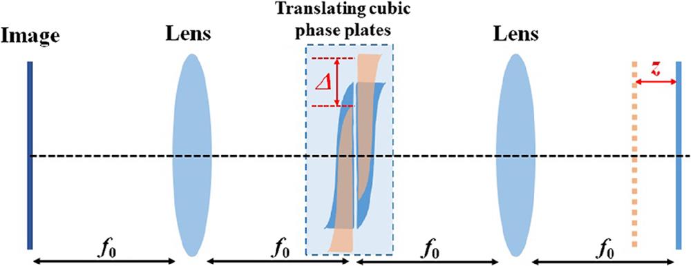
Fig. 1. Implementation of focus-tunable function using Lohmann lenses.
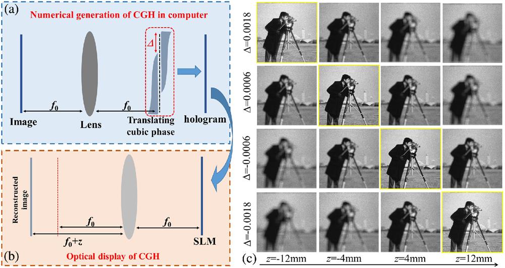
Fig. 2. CGH generation using Lohmann lens-based diffraction model. (a), (b) Analysis of CGH generation and reconstruction for focus-tunable holographic display. (c) Simulated results reconstructed from holograms generated using different translation amounts in a virtual Lohmann lens model.
Fig. 3. Fast 3D hologram generation using the split Lohmann lens-based diffraction model including depth-dependent virtual phase modulations. (a) Analysis of wavefront propagation from the target to the hologram in split Lohmann lens-based diffraction. By introducing a virtual phase modulation with piecewise slope in the frequency domain between two virtual cubic phase plates, we enable spatially varying axial shifts on the display of the generated hologram. We refer to this procedure as split Lohmann computer holography. (b) An illustration of the fast one-step pipeline of the CGH generation algorithm.
Fig. 4. Comparison of CGH computation run time between the proposed method and layer-based method.
Fig. 5. Numerical reconstructions of split Lohmann CGH and layer-based CGH. (a)–(c) The intensity image, depth map, and locally varied virtual phase of the multiplane 3D model “ABCD.” (d)–(f) The intensity image, depth map, and locally varied virtual phase of the 3D model “cars.” The depth map is quantized to 20 levels. (g), (h) The simulated reconstructions from the split Lohmann CGH. (i), (j) The simulated reconstructions from the layer-based CGH. The RMS and PSNR values are evaluated for each focused letter to quantitatively measure the reconstruction quality.
Fig. 6. Experimental results of monochromatic holographic 3D display. (a) Optical setup. (b)–(e) Optical reconstructions of 3D objects recorded by axially moving the CMOS sensor.
Fig. 7. Experimental results of full-color holographic near-eye display. (a) Schematic of holographic near-eye display prototype. An eyepiece lens is employed to magnify the 3D images, which are then recorded by adjusting the focus of the camera lens. (b)–(e) Two examples of RGBD input for the calculation of split Lohmann CGHs. (f)–(k) Experimental results of three focal sweep records when the camera is focusing on 2.5D, 1.0D, and 0D, respectively.
Fig. 8. Performance of image shift in CGH reconstruction. (a) Variation of shift along with the value of depth when fixing
Fig. 9. Performance of split Lohmann CGH with different quantization levels of depth map. The depth map is quantized into levels of
Fig. 10. Analysis of split Lohmann lens-based diffraction model. (a) Illustration of light-wave propagation from two distinct object points, demonstrating that the split Lohmann CGH can control the depth for each target object point. (b) Illustration of the artifacts where the target points are reconstructed at multiple planes due to the overlapping of their PSF at the plane of P3.
Fig. 11. Reconstruction of a split Lohmann CGH in Fresnel holography. (a) Conversion of Fourier holography to Fresnel holography by adding a virtual quadratic phase to the Fourier hologram. (b) Simulated reconstruction from Fourier hologram. (c) Simulated reconstruction from comverted Fresnel hologram.
|
Table 1. Comparison of CGH generation time (s).

Set citation alerts for the article
Please enter your email address
© Copyright 2018-2021 | Chinese Laser Press. All Rights Reserved 沪ICP备15018463号-20