• Photonics Research
  • Vol. 11, Issue 6, 953 (2023)
Longsheng Wang1、2, Junli Wang1、2, Yushan Wu1、2, Yuehui Sun3、4, Songsui Li5, Lianshan Yan5, Yuncai Wang3、4, and Anbang Wang1、2、3、4、*
Author Affiliations
  • 1Key Laboratory of Advanced Transducers and Intelligent Control System, Ministry of Education, Taiyuan 030024, China
  • 2College of Physics and Optoelectronics, Taiyuan University of Technology, Taiyuan 030024, China
  • 3School of Information Engineering, Guangdong University of Technology, Guangzhou 510006, China
  • 4Guangdong Provincial Key Laboratory of Photonics Information Technology, Guangzhou 510006, China
  • 5Center for Information Photonics & Communications, School of Information Science and Technology, Southwest Jiaotong University, Chengdu 610031, China
  • show less
    DOI: 10.1364/PRJ.478487 Cite this Article Set citation alerts
    Longsheng Wang, Junli Wang, Yushan Wu, Yuehui Sun, Songsui Li, Lianshan Yan, Yuncai Wang, Anbang Wang. Chaos synchronization of semiconductor lasers over 1040-km fiber relay transmission with hybrid amplification[J]. Photonics Research, 2023, 11(6): 953 Copy Citation Text show less
    (a) Fiber-loop experiment for investigating fidelity transmission of laser chaos; (b) setup of long-reach chaos synchronization. SL: semiconductor laser; DL: drive laser; RLA,B: response lasers; OI: optical isolator; EDFA: erbium-doped fiber amplifier; OF: optical filter; VOA: variable optical attenuator; FM: fiber mirror; PC: polarization controller; EOM: electro-optic modulator; AWG: arbitrary waveform generator; OC: optical coupler; SSMF: standard single-mode fiber; DCF: dispersion compensation fiber; WDM: wavelength division multiplexer; PD: photodetector.
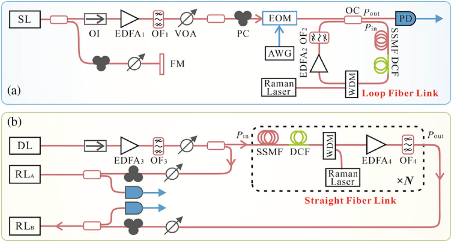
    Fig. 1. (a) Fiber-loop experiment for investigating fidelity transmission of laser chaos; (b) setup of long-reach chaos synchronization. SL: semiconductor laser; DL: drive laser; RLA,B: response lasers; OI: optical isolator; EDFA: erbium-doped fiber amplifier; OF: optical filter; VOA: variable optical attenuator; FM: fiber mirror; PC: polarization controller; EOM: electro-optic modulator; AWG: arbitrary waveform generator; OC: optical coupler; SSMF: standard single-mode fiber; DCF: dispersion compensation fiber; WDM: wavelength division multiplexer; PD: photodetector.
    Single-span fiber transmission. (a) Experimental and (b) simulated fidelities as a function of optical power launched into the fiber for a fixed loop length Lloop=120 km. EDFA gain GE=34.7 dB.
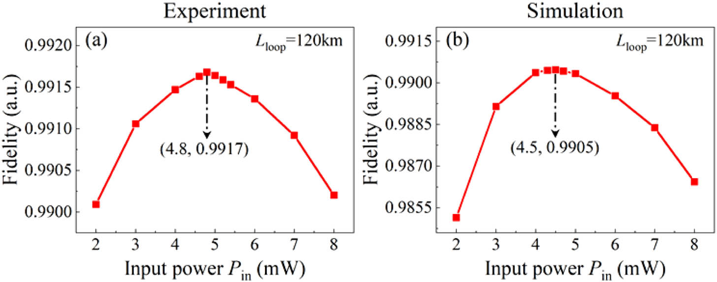
    Fig. 2. Single-span fiber transmission. (a) Experimental and (b) simulated fidelities as a function of optical power launched into the fiber for a fixed loop length Lloop=120  km. EDFA gain GE=34.7  dB.
    Single-span fiber transmission. (a) Experimental and (b) simulated maximum fidelities and optimum launching power as a function of fiber loop length.
    Fig. 3. Single-span fiber transmission. (a) Experimental and (b) simulated maximum fidelities and optimum launching power as a function of fiber loop length.
    Multispan fiber transmission with the EDFA relay. (a) Experimental and (b) simulated maximum fidelities as a function of relay number for different fiber loop lengths Lloop=90 km, 100 km, and 120 km.
    Fig. 4. Multispan fiber transmission with the EDFA relay. (a) Experimental and (b) simulated maximum fidelities as a function of relay number for different fiber loop lengths Lloop=90  km, 100 km, and 120 km.
    Single-span fiber transmission. (a) Experimental and (b) simulated fidelity as a function of optical power launched into the fiber at different gain ratios of the DFRA and the EDFA for a fixed fiber loop length Lloop=120 km. Total gain GD+GE=34.7 dB.
    Fig. 5. Single-span fiber transmission. (a) Experimental and (b) simulated fidelity as a function of optical power launched into the fiber at different gain ratios of the DFRA and the EDFA for a fixed fiber loop length Lloop=120  km. Total gain GD+GE=34.7  dB.
    Single-span fiber transmission. (a) Experimental and (b) simulated maximum fidelity, optimum launching power, and gain ratio as a function of the fiber loop length.
    Fig. 6. Single-span fiber transmission. (a) Experimental and (b) simulated maximum fidelity, optimum launching power, and gain ratio as a function of the fiber loop length.
    Multispan fiber transmission with the EDFA and the DFRA relay. (a) Experimental and (b) simulated maximum fidelities as a function of relay number for different fiber loop lengths Lloop=120 km, 130 km, and 150 km.
    Fig. 7. Multispan fiber transmission with the EDFA and the DFRA relay. (a) Experimental and (b) simulated maximum fidelities as a function of relay number for different fiber loop lengths Lloop=120  km, 130 km, and 150 km.
    Experimental results of a 1040-km chaos transmission over a straight fiber link using hybrid amplification. (a) Optical spectra; (b) radio-frequency spectra; (c) temporal waveforms; (d) scatter plot. Pin=Pout=5.4 mW, the DFRA gain GD=7.0 dB, and the EDFA gain GE=30.0 dB.
    Fig. 8. Experimental results of a 1040-km chaos transmission over a straight fiber link using hybrid amplification. (a) Optical spectra; (b) radio-frequency spectra; (c) temporal waveforms; (d) scatter plot. Pin=Pout=5.4  mW, the DFRA gain GD=7.0  dB, and the EDFA gain GE=30.0  dB.
    Experimental results of 1040-km chaos synchronization. (a) Optical spectra; (b) radio-frequency spectra; (c) temporal waveforms; (d) scatter plot. The injection strengths of RLA and RLB are 78% and 57%, respectively.
    Fig. 9. Experimental results of 1040-km chaos synchronization. (a) Optical spectra; (b) radio-frequency spectra; (c) temporal waveforms; (d) scatter plot. The injection strengths of RLA and RLB are 78% and 57%, respectively.
    1040-km chaos synchronization coefficient as a function of (a) time and (b) chaos bandwidth after low-pass filtering (LPF).
    Fig. 10. 1040-km chaos synchronization coefficient as a function of (a) time and (b) chaos bandwidth after low-pass filtering (LPF).
    ParameterSymbolValue
    Transparency carrier densityn01.5×1024  m3
    Linewidth enhancement factorα3.0
    Gain saturation coefficientε1×10²³  m3
    Linear gain coefficientg3×1020  m2
    Spontaneous emission rateβ0.001
    Length of the active regionl300 μm
    Width of the active regionw2.5 μm
    Grating periodτ200×109  m
    Threshold currentith20 mA
    Bias currentI1.2ith
    Static-state wavelengthλ1549.45 nm
    Feedback strengthkf1.5%
    Table 1. Simulation Parameters of the Semiconductor Laser
    ParameterSymbolValue
    Attenuation coefficient of the SSMFαs0.2 dB/km
    Attenuation coefficient of the DCFαD0.5 dB/km
    Dispersion coefficient of the SSMFβs17  ps  nm1km1
    Dispersion coefficient of the DCFβD153  ps  nm1km1
    Raman response coefficientρ0.17
    Fiber core areaAeff80×1012  m2
    SPM coefficientξ8/9
    Nonlinear refractive indexn2.6×1020  m2/W
    Filtering width of the OFΛ0.2 nm
    Noise figure of the EDFANFE4 dB
    Noise figure of the DFRANFD1.7  dB
    Table 2. Simulation Parameters of the Fiber, the Filter, and the Amplifier
    NumberLength (km)Dispersion (ps/nm)Attenuation (dB)
    First span130.0051.08430.40
    Second span130.0381.27830.10
    Third span129.8501.05429.72
    Fourth span130.048−0.99630.80
    Fifth span130.0152.86729.80
    Sixth span129.960−3.05130.83
    Seventh span129.974−2.54129.61
    Eighth span130.0591.41430.62
    Table 3. Parameters of Eight-Span Fibers
    Longsheng Wang, Junli Wang, Yushan Wu, Yuehui Sun, Songsui Li, Lianshan Yan, Yuncai Wang, Anbang Wang. Chaos synchronization of semiconductor lasers over 1040-km fiber relay transmission with hybrid amplification[J]. Photonics Research, 2023, 11(6): 953
    Download Citation