Optical chaos communication and key distribution have been extensively demonstrated with high-speed advantage but only within the metropolitan-area network range of which the transmission distance is restricted to around 300 km. For secure-transmission requirement of the backbone fiber link, the critical threshold is to realize long-reach chaos synchronization. Here, we propose and demonstrate a scheme of long-reach chaos synchronization using fiber relay transmission with hybrid amplification of an erbium-doped fiber amplifier (EDFA) and a distributed fiber Raman amplifier (DFRA). Experiments and simulations show that the hybrid amplification extends the chaos-fidelity transmission distance thanks to that the low-noise DFRA suppresses the amplified spontaneous emission noise and self-phase modulation. Optimizations of the hybrid-relay conditions are studied, including launching power, gain ratio of DFRA to EDFA, single-span fiber length, and number of fiber span. A 1040-km chaos synchronization with a synchronization coefficient beyond 0.90 is experimentally achieved, which underlies the backbone network-oriented optical chaos communication and key distribution.
1. INTRODUCTION
With the ever-growing demands of high-speed and long-haul optical fiber communication, which is beyond for metropolitan-area networks and for backbone networks [1], protecting data transmission from eavesdropping becomes increasingly important. Physical-layer optical chaos communication and key distribution have shown great potential in securing data transmission due to the advantages in the transmission rate, distance, and compatibility with existing fiber networks [2–6]. For example, Argyris et al. implemented semiconductor lasers-based chaos communication at 1 Gb/s over a 120-km fiber link in the metropolitan-area network of Athens in 2005 [3]. In 2010, Lavrov et al. demonstrated 10-Gb/s chaos communication using optoelectronic oscillators in the installed 100-km fiber network of Besancon [7]. Recently, Yang et al. and Wu et al. separately reported chaos communications at 30 Gb/s over a 340-km fiber and at 60 Gb/s over a 100-km fiber by adopting oscillators and high-order modulations [8,9]. In addition, Yoshimura et al. demonstrated a 120-km chaos key distribution at 184 kb/s with optical-feedback lasers [10]. Gao et al. achieved a 0.75-Gb/s chaos key distribution with 160-km fiber transmission utilizing Fabry–Perot lasers [11]. Concluding from these experimental reports, the transmission distances of chaos communication and key distribution are presently limited to around 300 km, which is only applicable to the metropolitan-area networks. Considering their envisioned applications in the backbone networks, the long-haul transmission with a longer distance becomes an urgent requirement.
For the long-haul chaos communication and key distribution, a primary challenge is establishing chaos synchronization [12] of transceiver after long-reach fiber transmission. To achieve the long-reach synchronization, the key is to mitigate fiber transmission-induced channel impairments, which distort the optical chaos [13], including chromatic dispersion of the fiber, self-phase modulation (SPM) induced by Kerr nonlinearity, and amplified spontaneous emission (ASE) noise caused by an erbium-doped fiber amplifier (EDFA). Early studies by Kanakidis et al. and Nguimdo et al. clarified the effects of fiber dispersion on chaos synchronization of lasers and oscillators, respectively [14,15]. A maximum synchronization distance at 400 km is predicted theoretically under the premise of delicate dispersion management and out-of-band ASE noise suppression [14]. This bottleneck of synchronization distance arises because the accumulated impairments from the SPM and inside-of-band ASE noise become no longer negligible. Recently, Yang et al. and Fu et al. successively proposed to mitigate fiber dispersion and the SPM by using coherent detection and digital signal processing algorithms while filtering the out-of-band ASE noise, and a 1000-km chaos synchronization of oscillators was demonstrated numerically [16,17], which has not been proven suitable for chaotic lasers. Note that, compared with the oscillator [18–20], a semiconductor laser with a simple and integratable setup is the main light source of optical fiber communication and is, therefore, a preferred one for chaos communication and key distribution [21–23]. However, it is still an open question that what is the limit of synchronization distance for laser chaos and whether this synchronization distance can satisfy the requirement of backbone networks.
In this paper, a long-reach laser chaos synchronization via hybrid relay of the EDFA and distributed fiber Raman amplifier (DFRA) is studied and demonstrated experimentally and numerically. First, chaos fidelity of fiber transmission is investigated by using a fiber loop with amplifiers, which is equivalent to cascaded fiber spans with relay. The loop length means the length of single fiber span. Then, by using the transmitted chaotic light as drive signal, long-reach common-chaos-induced synchronization between two semiconductor lasers is demonstrated over a 1040-km straight fiber link. The remainder of this paper is organized as follows. In Section 2, the experimental setup and theoretical model of fidelity transmission and synchronization of laser chaos are illustrated. In Section 3, results for chaos fidelity of fiber transmission with EDFA relay and with hybrid relay are presented and compared, and the long-reach chaos synchronization is demonstrated. Finally, a brief conclusion is drawn in Section 4.
Sign up for Photonics Research TOC. Get the latest issue of Photonics Research delivered right to you!Sign up now
2. EXPERIMENTAL SETUP AND THEORETICAL MODEL
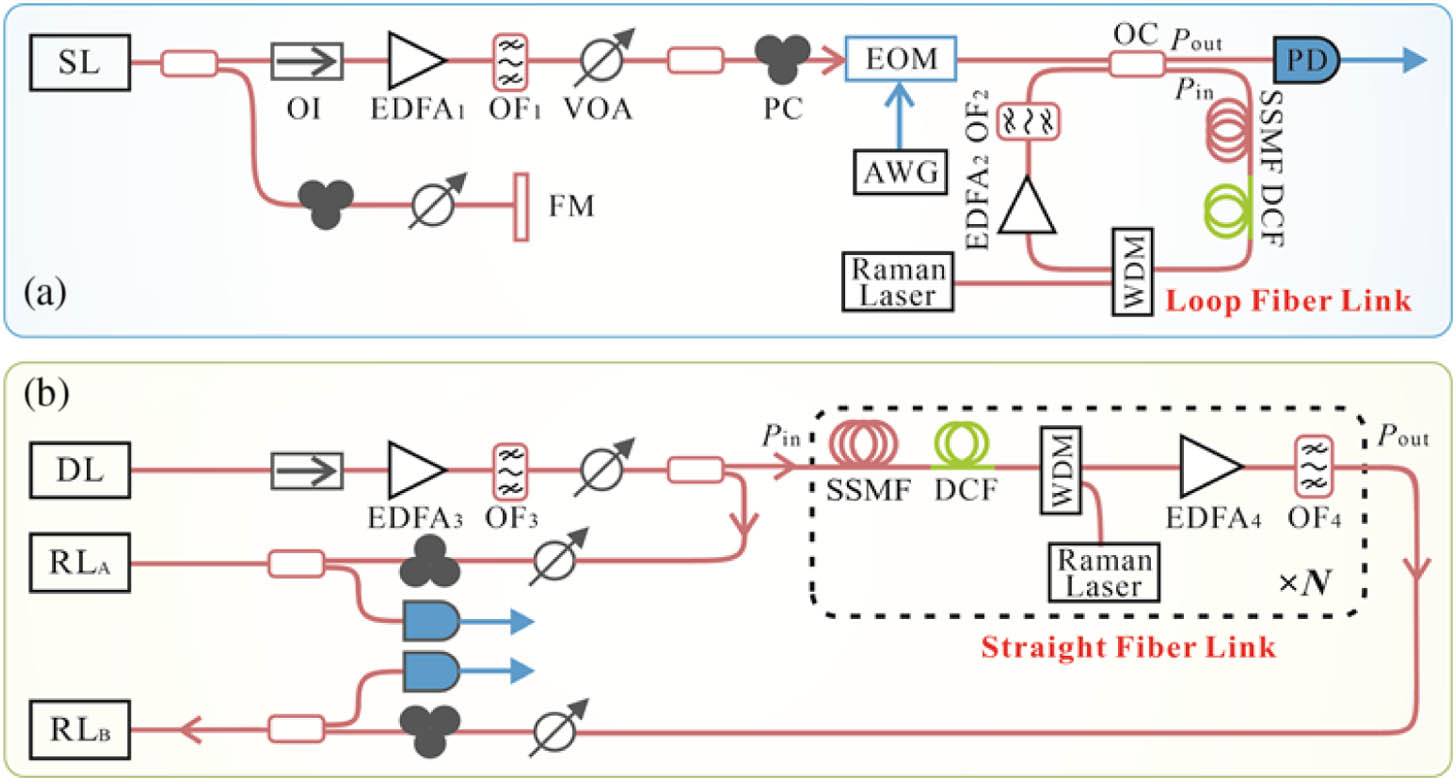
Figure 1(a) shows the experimental setup for investigating fidelity transmission of laser chaos with relay amplification, which is used for confirming the optimum conditions of establishing long-reach chaos synchronization. A semiconductor laser subject to mirror optical feedback generates laser chaos used as the transmission signal. This signal is first preamplified by followed by filtering out-of-band ASE noise by optical filter and then delivered into a fiber loop composed of an optical coupler, a standard single-mode fiber, and a dispersion compensation fiber. In the fiber loop, the DFRA composed of a Raman laser with backward pumping over the fiber and a wavelength division multiplexer and the are arranged for hybrid amplifying the chaotic signal, behind which another filter is further arranged for filtering the ASE noise. Note that, the scenario with hybrid amplification can be switched to that with only EDFA amplification by removing the Raman laser. Moreover, since the length of fiber loop can be varied flexibly, it is cost effective and convenient to investigate the transmission fidelities with different distances by delivering a chaotic signal over the fiber loop repeatedly, i.e., -cycle transmission. After the -cycle transmission, the chaotic signal is output through the optical coupler and detected by photodetector. Before the fiber loop, an electro-optic modulator periodically modulated by an arbitrary waveform generator is deployed as an optical switch to prevent cross talk between chaotic signals belonging to adjacent periods.
After confirming the conditions of chaos-fidelity transmission, we arrange the following setup as shown in Fig. 1(b) for achieving the long-reach common-chaos-induced synchronization, which can be applied to both chaos communication and key distribution. The mirror-feedback laser with chaotic output as shown in Fig. 1(a) is adopted as the drive laser (DL). The output from the DL is divided into two branches, and one is unidirectionally injected into the local response laser (RL) , and the other one into the via a long-reach transmission link with hybrid relay amplification to induce chaos synchronization. This long-reach scenario is achieved by directly deploying -span fibers composed of standard single-mode fibers and dispersion compensation fibers rather than by repeating transmission over the fiber loop.
The DL (Eblana, DM-1550) and response lasers (Junte, DFB-1550) used in experiments are custom made without internal isolators. The DL has a threshold current of 12.3 mA and is biased at 13.9 mA by the current controller (ILX Lightwave, LDX-3412) emitting at an optical power of 0.396 mW, 7% of which is reflected back to induce laser chaos. Its static-state wavelength is located at 1549.46 nm by adjusting the temperature controller (ILX Lightwave, LDT-5412) and redshifts to 1549.51 nm due to the feedback light. The thresholds of and are 16.0 mA and 16.6 mA, respectively, and they are individually biased at 22.4 mA and 20.8 mA making them have the same relaxation oscillation frequency of 4.0 GHz and the same static-state wavelength of 1549.49 nm. The electro-optic modulator (Eospace, AZ-DK5-20) has a 3-dB bandwidth of 10 GHz and a half-wave voltage of 2.8 V. The arbitrary waveform generator (RIGOL, DG4062) outputs a square signal with a period of 32 ms within which the high-level signal indicating a switch-on state lasts for 20 μs. The standard single-mode fiber (YOFC, G.652D) and dispersion compensation fiber (YOFC, BD NDCF) are well designed to compensate the chromatic dispersion as much as possible. The DFRA pumped by a Raman laser (CONQUER, FOL1437R50) has a maximum gain of 18 dB and a noise figure of at the pumping power of 500 mW. The wavelength division multiplexer (MWPHOTON, ) is used to launch the Raman laser into the fiber. The EDFA (YOFC, ERA-M-C-GB) with a noise figure of 4.2 dB can reach a maximum gain of 28 dB, and one more EDFA is used to jointly achieve gain exceeding 28 dB. The 3-dB filtering width of the custom-made optical filter (OPEAK) is fixed at about 0.2 nm. The photodetector (Finisar, XPDV2120RA) has a 3-dB bandwidth of 50 GHz. The laser outputs are measured by an optical spectrum analyzer (Yokogawa, AQ6370D, 0.02 nm), an electric spectrum analyzer (Rohde & Schwarz, FSW-50, 26 GHz), and a real-time oscilloscope (Tektronix, MSO73304DX, 33 GHz, 100 GS/s).
As a supplemental validation to the transmission experiment as shown in Fig. 1(a), simulations based on VPIphotonics software are also performed [24]. The parameters of laser, fiber, filter, and amplifier mainly used in the simulations are described in Tables 1 and 2, respectively.
Simulation Parameters of the Semiconductor Laser
Parameter
Symbol
Value
Transparency carrier density
Linewidth enhancement factor
3.0
Gain saturation coefficient
Linear gain coefficient
Spontaneous emission rate
0.001
Length of the active region
300 μm
Width of the active region
2.5 μm
Grating period
Threshold current
20 mA
Bias current
Static-state wavelength
1549.45 nm
Feedback strength
1.5%
Simulation Parameters of the Fiber, the Filter, and the Amplifier
Parameter
Symbol
Value
Attenuation coefficient of the SSMF
0.2 dB/km
Attenuation coefficient of the DCF
0.5 dB/km
Dispersion coefficient of the SSMF
Dispersion coefficient of the DCF
Raman response coefficient
0.17
Fiber core area
SPM coefficient
8/9
Nonlinear refractive index
Filtering width of the OF
0.2 nm
Noise figure of the EDFA
4 dB
Noise figure of the DFRA
3. RESULTS
A. Chaos Fidelity of Fiber Transmission with EDFA Relay
In this section, results demonstrating chaos transmission with the EDFA relay are presented. To evaluate the transmission performance quantitatively, the fidelity obtained by the cross-correlation function is utilized [16], which is defined as , where and represent chaotic temporal waveforms before and after transmission, respectively, and denotes time averaging. We first studied the fidelity evolution with respect to the signal power launched into fiber loop with a fixed length under the scenario of single-span transmission. That is, the first-cycle chaos output from the fiber loop is considered. Note that, the dispersion of the 120-km fiber is minimized as 0.722 ps/nm by a dispersion compensation fiber in the experiment and 0 ps/nm in the simulation. Besides, to have the chaotic signal launched into and out of the fiber loop as the same power, i.e., , the gain of the EDFA is fixed at to completely compensate the power loss of the fiber loop. From experimental results of Fig. 2(a), it can be seen that the fidelity increases with a reducing rate and starts to decrease after reaching the extreme value of 0.9917 at the optimum power of . Theoretically, as shown in Fig. 2(b), an evolution trend, which is consistent with the experimental result is also observed, and the maximum fidelity of 0.9905 is achieved at . This phenomenon can be explained as follows. With the increase in , the signal-to-noise ratio (SNR) improves due to the noise level kept constant under a fixed EDFA gain, which enhances the transmission fidelity of the chaotic signal. Meanwhile, the effect of the SPM will become stronger as increasing , which deteriorates the transmission fidelity. Before reaching the optimum power, the dominant effect on fidelity is the SNR rather than the SPM. After reaching the optimum power, the effects of the SNR and the SPM reach a balance yielding a highest transmission fidelity. Further increasing beyond the optimum power, the SPM becomes dominant, and the fidelity is beginning to downgrade.
Figure 2.Single-span fiber transmission. (a) Experimental and (b) simulated fidelities as a function of optical power launched into the fiber for a fixed loop length . EDFA gain .
We further studied the maximum fidelity and the corresponding optimum power under the single-span transmission when fiber loops with different lengths are considered. As displayed in Fig. 3, both the experimental and the simulated results indicate a similar evolution trend: as lengthening the fiber loop, the maximum fidelity (optimum power) experiences a slow and then rapid decrease (increase). For example, in experiment, the achieved fidelities are 0.9949 at , 0.9946 at , and 0.9917 at for , 100 km, and 120 km, respectively. The downgrading of transmission fidelity is attributed to the following reasons. First, the power loss in the fiber loop is multiplied with the increasing transmission distance. For instance, the total attenuation is increased from 34.7 to 46.5 dB as the loop length is experimentally increased from 120 km to 170 km. To fully compensate the extra power loss, the EDFA gain has to be enlarged, which inevitably introduces much more ASE noise worsening the SNR. Second, for a longer , one also needs to enlarge the optimum power. For example, by comparing the experimental results under scenarios of and 170 km, the optimum power is increased from 4.8 mW to 12 mW giving rise to a stronger SPM. It is worth mentioning that, although the fidelity degrades with the increasing fiber loop length, it still remains beyond 0.99 as long as the length does not exceed 120 km.
Figure 3.Single-span fiber transmission. (a) Experimental and (b) simulated maximum fidelities and optimum launching power as a function of fiber loop length.
Having confirmed the fidelity and optimum power in the single-span fiber transmission, attention is now turned to the long-distance multispan transmission with the EDFA relay. Three fiber loops with lengths of , 100 km, and 120 km are used in the experiment and simulation owing to their high fidelities in the single-span transmission. Seen from the experimental results in Fig. 4(a), all of the fidelities decrease with accelerated rates for the increasing relay number . This is because the ASE- and SPM-induced channel impairments are continually accumulated while transmitting in the loop repeatedly, which distorts the chaotic signal. For a longer fiber loop, more impairments are accumulated after -cycle transmission, and, thus, the fidelity decreases faster around the critical threshold of 0.92. Note that, only the chaotic drive signal with a fidelity not lower than 0.92 can be used to induce high-quality chaos synchronization with a synchronization coefficient not below 0.90, which will be explained later. Judging from Fig. 4(a), the maximum relay numbers are , 8, and 6 for , 100 km, and 120 km, respectively, for which the corresponding distance limits are 810 km, 800 km, and 720 km. The similar phenomena in terms of the fidelity reduction are also observed in the simulation as depicted in Fig. 4(b). However, it is noted that the simulated fidelities decline with almost average rates for the increasing relay number, which is different from the experimental result. This is mainly attributed to that a slight dispersion compensation error exists in the experimental system but not in the simulated system, which accelerates the fidelity degradation while increasing the relay number in experiment.
Figure 4.Multispan fiber transmission with the EDFA relay. (a) Experimental and (b) simulated maximum fidelities as a function of relay number for different fiber loop lengths , 100 km, and 120 km.
B. Chaos Fidelity of Fiber Transmission with EDFA and DFRA Relays
After ascertaining the transmission limit of laser chaos with an EDFA relay, the transmission performances with the hybrid relay of the EDFA and DFRA are further investigated in this section. First, the single-span transmission scenario is also considered with the same fiber loop length of . Figure 5 shows the fidelities obtained in experiment and simulation with respect to the signal power launched into the fiber at different gain ratios of the DFRA to the EDFA, i.e., . To make power launched into and out of the fiber the same, the gains of the DFRA and the EDFA are dynamically matched to fully compensate the constant transmission loss in the fiber loop. From Fig. 5, one can note a consistent fidelity evolution that is a gradual increase followed by a sudden reduction, which is similar with the trend using only the EDFA as shown in Fig. 2. This similar fidelity evolution trend is also caused by the dynamical balance between the effects of the SNR and the SPM, while increasing the input power as mentioned in Section 3.A. In addition to the similarity, the difference also exists between the two amplification scenarios: a higher fidelity at a smaller launching power is achieved with the hybrid amplification both in experiment and in simulation compared to that with only EDFA amplification. For example, the maximum fidelity of 0.9946 is experimentally achieved at the optimum power of with the hybrid gain ratio of , whereas, those values are 0.9917 and 4.8 mW for the solitary EDFA amplification. This should be thankful to that the DFRA with a low-noise figure reduces the gain of the EDFA, and, thus, suppresses the noise level of transmission channel especially the inside-of-band ASE noise. Moreover, assisted with the DFRA, the power launched into fiber can be decreased, which mitigates the SPM. We mention that a larger gain ratio cannot always yield a better fidelity because the DFRA with a high gain will also introduce the ASE noise deteriorating the chaotic signal. There exists an optimum gain ratio that balances the DFRA-induced improvement and deterioration in transmission performance, yielding a highest fidelity. For example, as plotted in Fig. 5(a) as the gain ratio increases from 0.129 to 0.208, the fidelity reaches the highest value of 0.9946 and then begins to degrade, further increasing the gain ratio.
Figure 5.Single-span fiber transmission. (a) Experimental and (b) simulated fidelity as a function of optical power launched into the fiber at different gain ratios of the DFRA and the EDFA for a fixed fiber loop length . Total gain .
Figure 6 further depicts the evolution of the optimum power and gain ratio as well as the corresponding fidelity when the fiber loop length is varied for the single-span transmission. As can be seen, the maximum fidelity declines gradually with the increase in loop length, and the optimum power and the gain ratio rise correspondingly either in the experiment or the simulation. For example, the fidelities are separately 0.9946 for , , and ; 0.9939 for , , and ; and 0.9905 for , , and in the experiment. The phenomenon in terms of fidelity decreasing is similar with that using the EDFA amplification as shown in Fig. 3. It is due to the same reason that additional amplification gain and input power are needed to compensate the extra transmission loss induced by extending the loop length. What should be paid more attention to is that the extreme transmission distance with a fidelity beyond 0.99 is lengthened from 120 km to 150 km benefitting from the hybrid amplification, compared to the scenario with only the EDFA amplification.
Figure 6.Single-span fiber transmission. (a) Experimental and (b) simulated maximum fidelity, optimum launching power, and gain ratio as a function of the fiber loop length.
Next, the multispan transmission performances with the EDFA and DFRA relays are evaluated by selecting fiber loops with , 130 km, and 150 km where we adopted the optimum launching power and gain ratio mentioned in Fig. 6(a). Figure 7 shows the fidelity evolution as a function of relay number in the experiment and the simulation. Results imply a fidelity decrease with increasing due to the continually accumulated channel impairments jointly caused by the ASE noise and the SPM. To keep the experimental fidelity not below 0.92, as shown in Fig. 7(a), the maximum relay numbers are , 8, and 6 for , 130 km, and 150 km, respectively, leading to the transmission limits of 960 km, 1040 km, and 900 km correspondingly. By comparing to the experimental results obtained by the EDFA relay as shown in Fig. 4(a), one can find that the maximum transmission distance has been increased by about 200 km using the hybrid relay. Comparison between the simulated results as presented in Figs. 7(b) and 4(b) also indicates an obvious distance improvement. Both the experimental and the simulated results prove that a single-span fiber with a length of 130 km is the best candidate for establishing the long-haul high-fidelity transmission using the multispan relay with hybrid amplification. It is mentioned again here that the slight rate divergence of fidelity degradation in the experiment and the simulation is due to the problem of dispersion compensation error as illustrated in Fig. 4.
Figure 7.Multispan fiber transmission with the EDFA and the DFRA relay. (a) Experimental and (b) simulated maximum fidelities as a function of relay number for different fiber loop lengths , 130 km, and 150 km.
C. Chaos Synchronization over 1040-km Fiber Transmission
In Sections 3.A and 3.B, we investigated and compared the transmission performances of the chaotic drive signal using the solitary relay of the EDFA and hybrid relay of the EDFA and the DFRA. With these investigations, we confirmed the optimum conditions for long-reach transmission using the hybrid amplification, including the length of the single-span fiber, relay number, signal power launched into fiber, and gain ratios of the DFRA to the EDFA. Based on these optimum conditions, we finally constructed a long-reach chaos synchronization system with a straight transmission link as shown in Fig. 1(b). This transmission link consists of eight-span 130-km fibers as illustrated in Table 3, comprising an overall length of 1040 km. In each span, the chaotic drive signals launched into and out of the fiber have the same power of 5.4 mW, and the gains of the DFRA and the EDFA are fixed at 7.0 dB and 30.0 dB, respectively, leading to a gain ratio of 0.233.
Parameters of Eight-Span Fibers
Number
Length (km)
Dispersion (ps/nm)
Attenuation (dB)
First span
130.005
1.084
30.40
Second span
130.038
1.278
30.10
Third span
129.850
1.054
29.72
Fourth span
130.048
−0.996
30.80
Fifth span
130.015
2.867
29.80
Sixth span
129.960
−3.051
30.83
Seventh span
129.974
−2.541
29.61
Eighth span
130.059
1.414
30.62
Figure 8 shows the characteristics of the chaotic drive signal before and after the 1040-km transmission. The optical spectra in Fig. 8(a) indicate a consistency within a region nearby the wavelength of 1549.51 nm. Outside this region, the inconsistency induced by residual channel impairments of the ASE noise and the SPM arises. Figure 8(b) further depicts the radio-frequency spectra. The signal components lower than the relaxation oscillation frequency coincide well, but the components higher than it have a striking difference. To evaluate the consistency quantitatively, we depicted the signals’ temporal waveforms, which are vertically shifted for easy comparison and their scatter plot as presented in Figs. 8(c) and 8(d). The consistent temporal oscillation with a fidelity of 0.9212 can be achieved, which matches well with the results in Fig. 7. We mention that the high fidelity is calculated within the frequency components of and is mainly contributed by the consistent low-frequency components, which have much higher power than the high-frequency ones. Moreover, it is worth noting that the compensation error of fiber dispersion exists in each span as shown in Table 3, but the total dispersion in the straight fiber link with multispan relay is as small as 1.109 ps/nm because the compensation errors can be neutralized between each span.
Figure 8.Experimental results of a 1040-km chaos transmission over a straight fiber link using hybrid amplification. (a) Optical spectra; (b) radio-frequency spectra; (c) temporal waveforms; (d) scatter plot. , the DFRA gain , and the EDFA gain .
Furthermore, Fig. 9 shows the experimental results of 1040-km chaos synchronization obtained by injecting the drive signal into response lasers and at an injection strength of 78% and 57%, respectively. The injection strength is defined as the optical power ratio of the injection light to the response laser output. As shown in Fig. 9(a), and have similar optical spectra with their central wavelengths both located at that (1549.51 nm) of the drive signal due to the injection-locking effect [25]. However, an obvious divergence arises as the wavelength increases towards the long-wavelength direction. The corresponding radio-frequency spectra are plotted in Fig. 9(b). It is seen that the chaos bandwidth is widened compared with that of the DL. The reason is that high-frequency chaotic oscillations are introduced by the transient interference of the injection-locked field and redshift cavity resonant field in the response laser under the condition of strong injection [26]. It is partially due to the transient interference that the consistency of high-frequency components is not as high as that of low-frequency ones located at . The temporal waveforms and their scatterplots are presented in Figs. 9(c) and 9(d), respectively. By cross-correlating temporal waveforms located in the range of , a high-quality chaos synchronization with a synchronization coefficient of 0.9043 is achieved, which proves the feasibility of long-reach common-drive synchronization over a 1040-km fiber relay transmission with hybrid amplification. The long-reach synchronization can also be achieved in the master-slave configuration [27], which has the same physical mechanism of injection locking as the common-drive configuration by guaranteeing the high-fidelity transmission of chaotic outputs from master laser using the hybrid amplification. Note that, we adopted 0.90 as the threshold of chaos synchronization because it is an acknowledged criterion for implementing chaos communication and key distribution successfully [11,22,23]. We further mention that the response lasers’ parameters are not ideally matched due to the fabrication deviation [28], and, thus, the achieved synchronization coefficient has a slight decline compared to the fidelity of 0.9212. This is the reason why we select the chaotic drive signal with transmission fidelity not lower than 0.92 to induce the high-quality chaos synchronization as mentioned in Sections 3.A and 3.B. It is speculated that a significant increase from the present synchronization distance of 1040 km using the hybrid amplification will become a great challenge. This is because the channel impairments to the analog drive signal cannot be mitigated completely either using the optical-domain or the digital-domain methods. A more practical way is to replace the analog drive signal with a digital one resisting the channel impairments better, which is outside the scope of this paper and will be discussed in another one. In addition, considering the application of the long-reach synchronization, for instance, in chaos communication, the key is how to implement the simultaneous transmission of drive chaos and carrier chaos. To solve this issue, the wavelength division multiplexing technology can be used to have them transmitted with different wavelengths over the fiber link [22,29]. It is worth noting that the wavelength space between them should be set appropriately to avoid the degradation of the synchronization quality caused by cross-phase modulation, which deserves a detailed investigation in the future.
Figure 9.Experimental results of 1040-km chaos synchronization. (a) Optical spectra; (b) radio-frequency spectra; (c) temporal waveforms; (d) scatter plot. The injection strengths of and are 78% and 57%, respectively.
Finally, to verify the synchronization stability, we recorded chaotic temporal waveforms within 93 min at an interval of 3 min and calculated the corresponding synchronization coefficients. As shown in Fig. 10(a), an average synchronization coefficient of 0.9041 with a standard deviation of 0.0114 is achieved over the recording time, which proves the long-time stability. We speculate that this slight deviation is caused by the random rotation of the drive signal’s polarization affecting the injection strength. A polarization tracker used for stabilizing the polarization state will help to reduce this deviation. Figure 10(b) further plots the synchronization coefficient with respect to the chaos bandwidth after low-pass filtering. It is seen that the synchronization coefficient increases monotonously with the reduction of the chaos bandwidth, meaning that a higher-quality chaos synchronization can be achieved by sacrificing the chaos bandwidth. This phenomenon is due to the low-frequency chaotic signals coinciding better than the high-frequency ones as shown by the radio-frequency spectra in Fig. 9(b), which can be understood as follows. (i) System noise from the fiber channel, the laser, and the detection equipment is mostly accumulated over the high-frequency band. Reducing the chaos bandwidth by low-pass filtering will get less noise involved, thus, yielding a better consistency and a higher synchronization coefficient in the low-frequency components. (ii) The high-frequency chaotic components result from the transient interference of the injection-locked field and redshift cavity resonant field under the strong injection. The transient interference is susceptible to the system noise and parameter mismatch of lasers, degrading the consistency and synchronization coefficient of the high-frequency components.
Figure 10.1040-km chaos synchronization coefficient as a function of (a) time and (b) chaos bandwidth after low-pass filtering (LPF).
In conclusion, the long-distance transmission performance of laser chaos by evaluating the fidelity was demonstrated in both experiment and theory for two relay scenarios: solitary amplification with the EDFA and hybrid amplification with the EDFA and the DFRA. Results show that the hybrid amplification has a better performance over the solitary amplification in terms of extending the chaos transmission distance with a fidelity not lower than 0.92 due to the DFRA-induced suppression of the ASE noise and the SPM. We obtained the optimum conditions for realizing long-reach high-fidelity chaos transmission using the hybrid amplification, including single-span fiber length, relay number, signal launching power, and gain ratio of the DFRA to the EDFA. With these optimum conditions, we finally constructed a 1040-km common-chaos-induced synchronization with high stability over a straight transmission link composed of eight-span 130-km fibers with dispersion compensation. This paper provides an alternative of establishing long-reach chaos synchronization and paves the way for long-haul optical chaos communication and key distribution.