
Tingyu Yan, Chunmin Zhang, Qiwei Li, Yutong Wei, Jirui Zhang. Efficient background removal based on two-dimensional notch filtering for polarization interference imaging spectrometers[J]. Chinese Optics Letters, 2016, 14(12): 123002
- Chinese Optics Letters
- Vol. 14, Issue 12, 123002 (2016)
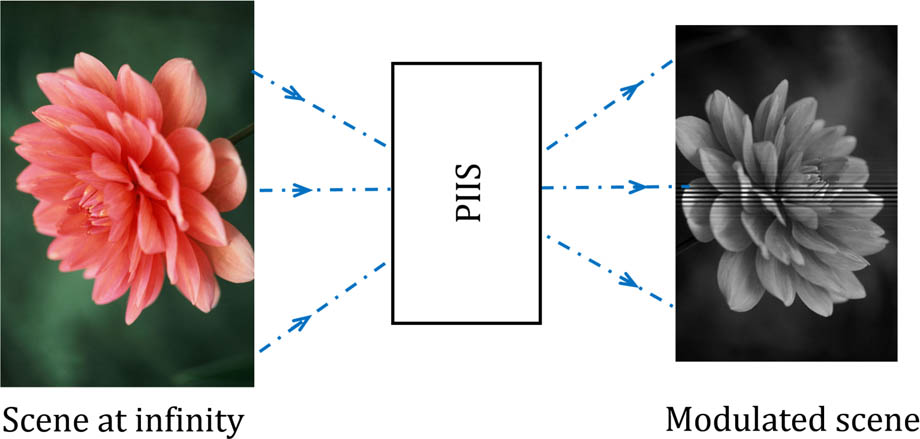
Fig. 1. Data acquisition process of PIIS. The modulated scene is the superposition of the interferogram and the background (fusion generated by computer). The scanning system is not shown.
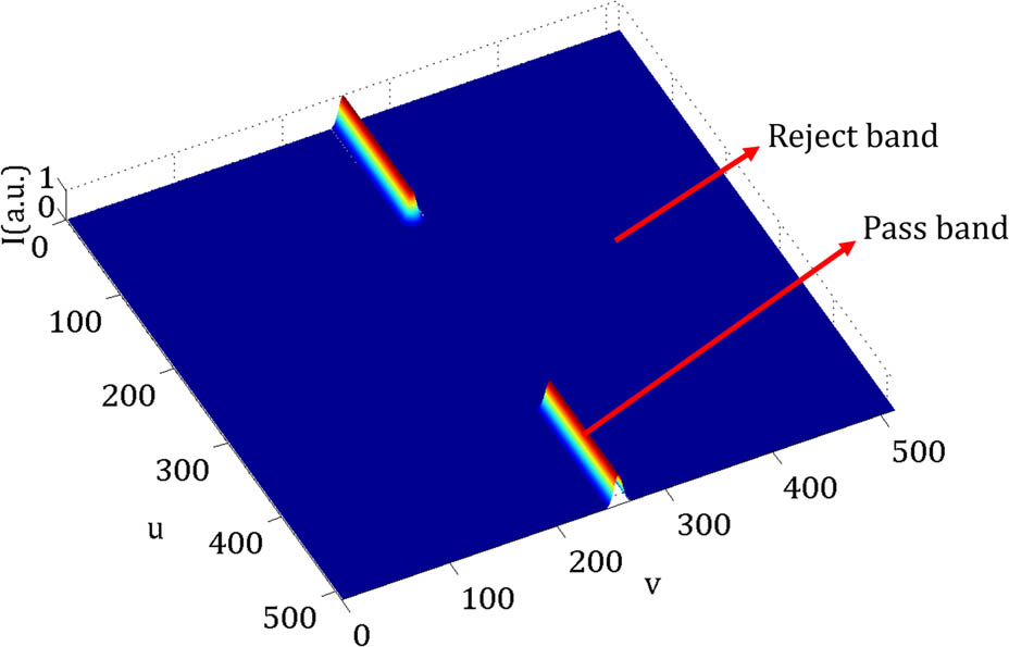
Fig. 2. Structure of the notch filter. The size of the filter is 512 × 512
Fig. 3. Filtering procedure for background removal. In the frequency domain, the frequency image was multiplied by the notch filter.
Fig. 4. Simulation results of background removal based on notch filtering. (a) The original interferogram overlaid with the background. (b) The background extracted by notch filtering. (c) The interferogram without the background.
Fig. 5. Simulation results of spectrum restore effect using different background removal methods: (a) polynomial fitting method, (b) EMD method, (c) notch filtering method. The red dashed dot line represents the original noise free spectrum, and the blue solid line represents the recovered spectrum after background removal using different methods.
Fig. 6. Spectrum of the He–Ne laser reconstructed after background removal using two methods. Red dashed dot line represents the polynomial fitting method, and blue solid line represents the notch filtering method.
Fig. 7. (a) The result using polynomial fitting method. (b) The result using EMD method. (c) The result using notch filtering method. And BR is the abbreviation of background removal.
Fig. 8. Separation of interferogram and background using notch filtering method when the background is complicated.
|
Table 1. Processing Time of the Background Removal Methods

Set citation alerts for the article
Please enter your email address
© Copyright 2018-2021 | Chinese Laser Press. All Rights Reserved 沪ICP备15018463号-20