
Qizhen Sun, Liuyang Yang, Dongchen Xu, Geng Chen, Anqi Wang, Chenhao Dai, Yanpeng Li, Zhijun Yan. Technology and Application Progress of Fiber-Optic Ultrasound Transducer[J]. Chinese Journal of Lasers, 2022, 49(12): 1210001
- Chinese Journal of Lasers
- Vol. 49, Issue 12, 1210001 (2022)
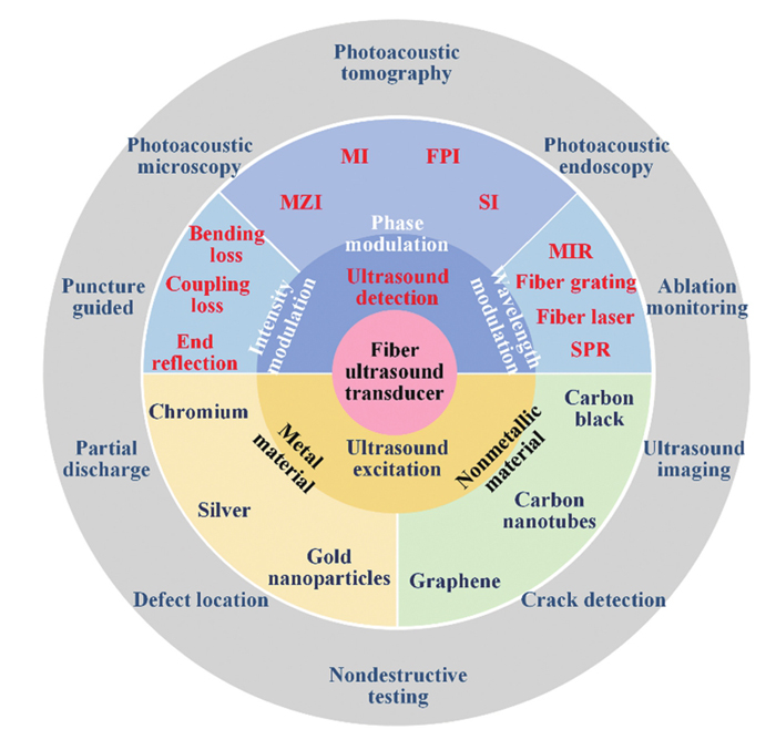
Fig. 1. Research progress and application of ultrasound transducer technology based on optical fiber
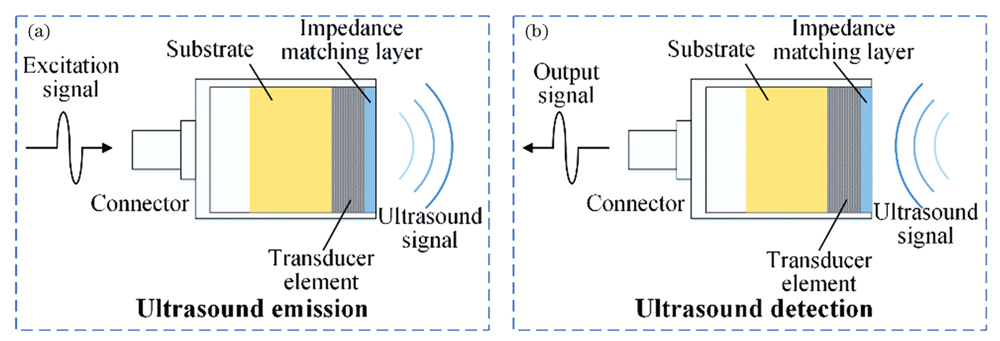
Fig. 2. Working mechanism of ultrasound transducer. (a) Schematic of ultrasound emission; (b) schematic of ultrasound detection
Fig. 3. Metallic material fiber optic ultrasound transmitters. (a) Schematic of the objective gold nanopores on the fiber end face[5]; (b) fiber-optic ultrasound transmitter coated with gold nanoparticles/PDMS composite material[9]; (c) schematic of excitation angle control and (d) diagram of the sound field distribution based on fiber optic ultrasound transmitter array[11]
Fig. 4. Nonmetallic material fiber optic ultrasound transmitters. (a)-(c) SEM images of fiber optic ultrasound transmitter coated with carbon nanofiber[19]; (d) SEM image of a optical fiber end coated with MWCNT[18]; (e) SEM image of fiber optic ultrasound transmitter coated with MWCNT/PDMS composite[18]; (f)(g) top view and side view of fiber optic ultrasound transmitter based on CIS-QDs/PDMS composite material[20]; (h) absorption spectrum of the CIS-QDs/PDMS based fiber optic ultrasound transmitter[20]
Fig. 5. Intensity modulated fiber optic ultrasound sensors. (a) Intensity modulated fiber optic ultrasound sensor based on fiber coupler; (b) fiber optic ultrasonic sensor based on reflectivity of fiber end face
Fig. 6. Phase modulated fiber optic ultrasound sensors. (a) Fiber optic ultrasound sensor based on MZI; (b) fiber optic ultrasound sensor based on MI; (c) fiber optic ultrasound sensor based on FPI; (d) fiber optic ultrasound sensor based on SI
Fig. 7. Wavelength modulated fiber optic ultrasound sensors. (a) Fiber optic ultrasound sensor based on fiber grating[68]; (b) fiber optic ultrasound sensor based on fiber laser[70];(c) fiber optic ultrasound sensor based on micro-ring resonator[37]; (d) fiber optic ultrasound sensor based on SPR[71]
Fig. 8. Separated fiber optic ultrasound transducers. (a) Fiber optic ultrasound probe composed of fiber optic ultrasound transmitter and a fiber optic FPI ultrasound sensor[86]; (b) fiber optic ultrasound probe composed of fiber optic ultrasound transmitter and fiber laser type ultrasound sensor[87]
Fig. 9. Integrated fiber optic ultrasound transducers. (a) Schematic of ultrasound detection based on an integrated fiber optic ultrasound transducer[88]; (b) an integrated fiber optic ultrasound transducer based on selective absorption composite film[90]
Fig. 10. Photoacoustic tomography applications of fiber optic ultrasound transducer technology[97]. (a) Photoacoustic tomography system based on an FPI type fiber optic ultrasound sensor; (b) photoacoustic tomography system based on a fiber laser ultrasound sensor
Fig. 11. Photoacoustic microscopy imaging applications of fiber optic ultrasound transducer technology. (a) Fast photoacoustic microscopy imaging system based on a fiber FPI ultrasound sensor[101]; (b) schematic of rapid microscopy imaging system and hemodynamics based on a fiber laser ultrasound sensor and blood flow images[100]
Fig. 12. Endoscopic imaging applications of fiber optic ultrasound transducer technology. (a) Forward endoscopy imaging system based on a fiber optic ultrasound sensor array[106]; (b) lateral endoscopy imaging system based on a fiber optic ultrasound sensor[107]
Fig. 13. Ultrasound imaging applications of fiber optic ultrasound transducer technology. (a) 3D pulse-echo ultrasound image of ex vivo porcine aorta[62]; (b) lateral ultrasound imaging system based on a fiber optic ultrasound transmitter and a fiber laser ultrasound sensor, and cross-section ultrasound image of a pig trachea[87]; (c) freehand ultrasound imaging probe and application of human vascular imaging based on all-fiber ultrasound transducer technology[112]
Fig. 14. Nondestructive testing applications of fiber optic ultrasound detecting technology. (a) Damage detection system of carbon fiber composite laminates using piezoelectric ultrasound transmitter and FBG ultrasound sensors[115]; (b) a flower-shaped FBG ultrasound sensor structure for sound source location[118]; (c) a nondestructive testing method based on the combination of a FBG ultrasound sensor and an MZI ultrasound sensor[123]; (d) schematic of acoustic emission detection of structural damage based on phase-shifted grating ultrasound sensor[121]; (e) Lamb wave signals measured by FBG ultrasound sensor and identification results[121]
Fig. 15. Applications of fiber optic ultrasound detection technology in partial discharge. (a) Schematic of discharge detection based on Sagnac fiber interferometer[127]; (b) discharge detection system based on fiber FPI[128]; (c) discharge detection system based on distributed FBG ultrasound sensors[129]; (d) discharge detection system based on fiber MI[130]; (e) partial discharge detection system based on φ-OTDR and the measured discharge signal position[132]
|
Table 1. Comparison among fiber optic ultrasound transmitters
|
Table 2. Comparison among fiber-optic ultrasound sensors

Set citation alerts for the article
Please enter your email address
© Copyright 2018-2021 | Chinese Laser Press. All Rights Reserved 沪ICP备15018463号-20