
Yurui Wang, Mei Zhang, Ke Xiao, Renxing Lin, Xin Luo, Qiaolei Han, Hairen Tan. Recent progress in developing efficient monolithic all-perovskite tandem solar cells[J]. Journal of Semiconductors, 2020, 41(5): 051201
- Journal of Semiconductors
- Vol. 41, Issue 5, 051201 (2020)
Abstract
1. Introduction
Organic–inorganic metal halide perovskites have become attractive light absorber materials for solar cells due to their high optical absorption coefficient, long carrier diffusion length, low trap density, tunable bandgap, and simple processing[
Fabricating tandem solar cells by combining subcells with different bandgaps offers an avenue to go beyond the Shockley-Queisser limit[
The bandgap tunability enables metal halide perovskites to construct perovskite-perovskite (all-perovskite) tandem solar cells[
In the early stage, all-perovskite tandem solar cells showed much lower performance compared to single-junction PSCs[
![]()
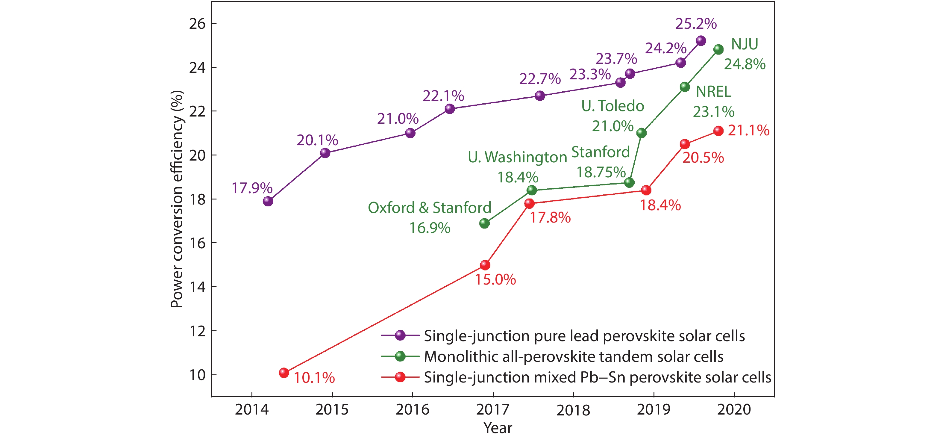
Figure 1.(Color online) The PCE evolution of single-junction PSCs and all-perovskite tandem solar cells.
Here we give a short review on recent research progress in improving the efficiency of all-perovskite tandem solar cells. In Section 2, we present the structure and working mechanism of all-perovskite tandem solar cell. Fig. 1 and Table 1 show the PCE evolution of all-perovskite tandem solar cells in the past few years. In Section 3, we summarize recent progress in improving the efficiency of all-perovskite tandem solar cells in three aspects: tunnel recombination junction, wide-bandgap top subcell, and narrow-bandgap bottom subcell. Finally, we summarize in Section 4 the remaining issues that constrain the performance of all-perovskite tandem solar cells. We thereby provide an outlook and perspective for future development of all-perovskite tandem solar cells.
2. Device structure and working mechanism
2.1. Device structure and working mechanism of all-perovskite tandem solar cell
Unless otherwise stated, tandem solar cells are referred to monolithic two-terminal devices in this review article. The monolithic all-perovskite tandem solar cell includes two subcells: the top subcell made of a wide-bandgap perovskite and the bottom subcell using a narrow-bandgap perovskite, as shown in Fig. 2(a). The subcells are connected with a tunnel recombination junction (also called interconnecting layer or charge recombination junction). The current in subcells should be matched to deliver optimal performance. The photocurrent of tandem solar cells follows the Kirchhoff's law[
![]()
Figure 2.(Color online) (a) Schematic structure of monolithic all-perovskite tandem solar cells. (b) Absorption of different wavelengths of light by different bandgap subcells. (c) Solar irradiance spectrum showing the spectral regions over which the two semiconductors could absorb. Reproduced with permission[
Sunlight consists of a broad energy spectrum with varying intensity, ranging from ultraviolet (photon energy higher than 3 eV) to infrared (photon energy lower than 1.7 eV to about 0.5 eV). When light is incident on a semiconductor, light with energy higher than the bandgap is absorbed, and light with energy lower than the bandgap is passed through without absorption, as shown in Fig. 2(b). The excess energy of the photon (above the bandgap energy) is lost as heat due to electron thermalization. The trade-off between harvesting more photons and minimizing thermalization loss in single-junction photovoltaic devices limits their theoretical maximum PCE (Shockley-Queisser limit)[
The working principle of tandem solar cells is to combine two subcells with different bandgaps, thereby absorbing a region of sunlight in each subcell to improve performance by reducing thermalization loss[
Theoretically, the open-circuit voltage (Voc) in a tandem solar cell is nearly the sum of the Voc of two subcells, where the Voc loss is mainly caused by the tunnel recombination junction. The short-circuit current density (Jsc) value in the device is the smaller one of two subcells. Furthermore, the thickness of subcells has a significant effect on light capturing and thus the resulting Jsc. Both bandgap and absorber thickness matching are required in all-perovskite tandem solar cells to achieve optimal performance. Fig. 2(d) shows the maximum PCE of tandem solar cells with different bandgap matching. For all-perovskite tandem solar cells, the best bandgap matching is considered to be that the bottom subcell has a bandgap around 1.2 eV and the top subcell has a bandgap around 1.8 eV[
2.2. Bandgap tuning of perovskite materials
Perovskite materials have a general structural formula: ABX3, A+ is usually an organic cation, B2+ is a metal ion, and X- is a halogen ion. We list the different substitution types in Fig. 3(a). The bandgap can be continuously tune between 1.2 and 2.5 eV by adjusting the composition[
![]()
Figure 3.(Color online) Schematic of the structure and bandgap tuning of perovskite. (a) Perovskite structure and selectable bandgap tuning ions. (b) UV–vis absorption spectra of the MAPb(I1–
2.2.1. Pure lead wide-bandgap perovskite
This is the most common strategy to obtain a perovskite material with a wider bandgap by partial substitution of I– with Br–. For a typical MAPbX3 perovskite, the bandgap can be continuously widened from 1.58 eV (0%-Br) to 2.28 eV (100%-Br) by increasing the proportion of Br- at X-site. It can be seen from Fig. 3(b) that when the bromine content in MAPb(I1–xBrx)3 is gradually increased, the onset absorption band is tuned from 786 to 544 nm[
Partial substitution of the A-site using DMA+ (DMA is dimethylammonium) also leads to widening of the bandgap (Fig. 3(e))[
2.2.2. Mixed Pb–Sn narrow-bandgap perovskite
Partial substitution of Sn2+ with Pb2+ at B-site can further lower the bandgap of tin halide perovskites[
Additionally, the radius of the A-site ion can tune the bandgap of the perovskite by affecting the structure of the lattice[
3. Recent progress in monolithic all-perovskite tandem solar cells
We can divide the structure of all-perovskite tandem solar cells into three crucial parts: the top subcell, the bottom subcell, and the tunnel recombination junction (interconnecting layer). We next summarize the progress in all-perovskite tandem solar cells in these three parts. Details of all-perovskite tandem solar cells developed so far can be found in Table 1.
3.1. Tunnel recombination junction
One challenge in fabricating tandem solar cells is how to protect the top subcells when depositing the bottom subcells using solution processing. A tunnel recombination junction (also known as interconnecting layer) is required for electrical series connection between subcells in all-perovskite tandem solar cells. The tunnel junction must meet following requirements: (1) It must form ohmic contact with the charge extraction layers, promote the recombination of electrons and holes from subcells, and lead to as small series resistance loss as possible. (2) It must be compact enough to protect the top subcell from damage when depositing the bottom subcell. (3) It must have sufficient optical transparence to ensure low parasitic absorption.
The structure of tunnel recombination junction is continuously evolving in the development of all-perovskite tandem solar cells. At present, conductive transparent materials are deployed in tunnel junction for tandem solar cells, such as N4,N4,N4”, N4”-tetra([1,1’-biphenyl]-4-yl)-[1,1’:4’,1”-terphenyl]-4’,4”-diamine(TaTm) doped with 2,2’-(perflfluor-onaphthalene-2,6-diylidene) dimalononitrile(TaTm:F6-TCNNQ), poly(3,4-ethylenedioxythiophene) polystyrene sulfonate (PEDOT:PSS), aluminum doped zinc oxide (AZO), and indium tin oxide (ITO). Deposition techniques include vacuum deposition[
There are two strategies to avoid damaging the top subcell when the bottom subcell is deposited on top: (1) process the bottom subcell using non-solution approach; and (2) deploy a dense tunnel recombination junction to prevent the solvent from damaging the top subcell. We will introduce the recent progress of tunnel recombination junction used in all-perovskite tandem solar cells from following three aspects.
3.1.1. Lamination for connecting subcells
Im et al. used a 2-micron hole-transport layer (PEDOT: PSS) as a recombination layer in their early work to assemble two independent subcells by lamination, as shown in Fig. 4(a)[
![]()
Figure 4.(Color online) Schematic structures of all-perovskite tandem solar cells with different tunnel recombination junctions. (a) Structure of a tandem solar cell with a lamination for connecting subcells. Reproduced with permission[
3.1.2. Tunnel junction for bottom subcell processed by non-solution methods
Vacuum deposition is a useful way to process perovskite films. Snaith et al. used spin-coated PEDOT:PSS as the tunnel recombination junction, as shown in Fig. 4(b). PbI2 films were deposited by thermal evaporation on top of the front subcell, and then converted to perovskite by reacting with MAI in isopropanol solution through interdiffusion[
Other tunnel recombination junctions have also been reported to protect top subcells when processing bottom subcells using vacuum deposition. Sessolo et al. developed the N4, N4, N4″, N4″ -tetra([1,1′-biphenyl]-4-yl)-[1,1′: 4′, 1″ -terphenyl] -4,4″ -diamine(TaTm) as the charge recombination layer, whose conductivity can be increased by two orders of magnitude after doping with 2,2′-(Perfluoronaphthalene-2,6-diylidene) dimalononitrile (F6-TCNNQ)[
3.1.3. Dense tunnel recombination junction for full solution processing of perovskites
Processing a dense tunnel recombination junction is considered to be the best strategy to protect the top subcell from solvents in subsequent processing. In 2015, Zhou et al. firstly demonstrated bottom-up solution-processed all-perovskite tandem solar cells via designing a novel tunnel recombination junction: Spiro-OMeTAD/PEDOT:PSS/PEI/PCBM:PEI, as shown in Fig. 4(d). This tunnel recombination junction is efficient to collect electrons and holes from its top and bottom subcells, and robust enough to protect the top perovskite film during the bottom perovskite film deposition[
Sputtered ITO is widely used in semitransparent solar cells as the transparent electrode due to its high optical transparency in the visible and near-infrared (NIR) regions[
Since then, ITO based tunnel recombination junction has been widely used in p–i–n structured all-perovskite tandem solar cells. The difference is that in order to reduce the damage to the top subcell during the sputtering process, different protective buffer layers are searched. Jen et al. sputtered ITO as the charge recombination layer on C60/Bis-C60 (Fig. 4(f)). By combining a narrow-bandgap (1.2 eV) perovskite and a wide-bandgap (1.8 eV) perovskite, using indene-C60 bis-adduct (IC60BA) as the electron transport layer, They achieved a Voc of 1.98 V, which reached 80% of the theoretical limit[
Atomic layer deposition (ALD) is the key technology for constructing a compact buffer layer. The use of a nucleation layer to improve the compactness of the tunnel recombination junction has recently been demonstrated by Moore et al.[
During the same time, our group fabricated all-perovskite tandem solar cells with a configuration of glass/ITO/PTAA (poly(triarylamine)/wide-Eg perovskite/C60/ALD-SnO2/Au(~1 nm)/PEDOT:PSS/low-Eg perovskite/C60/BCP/Cu[
3.2. Progress in wide-bandgap perovskites
The performance of tandem solar cells closely depends on the performance of each. Compared with narrow-bandgap perovskites, wide-bandgap perovskites have been studies more extensively[
In the early stages of developing all-perovskite tandem solar cells, Im et al. and Ho-Baillie et al. used CH3NH3PbBr3 (2.3 eV) as top subcell[
According to the bandgap matching rules in tandem solar cells, researchers often choose the combination of wide-bandgap (~1.8 eV) perovskites and narrow-bandgap (~1.2 eV) perovskites to fabricate tandem solar cells. In 2016, Snaith et al. achieved a high-efficiency, stable perovskite of FA0.83Cs0.17Pb(I0.5Br0.5)3 (1.8 eV) by using a mixture of FA+ and Cs+ cations and adjusting the Br–/I– ratio[
![]()
Figure 5.(Color online) Performance of all-perovskite tandem solar cell with improved performance in the wide-bandgap top subcell. (a)
In tandem solar cells, the Voc is more provided by the wide-bandgap subcell[
As a photostable perovskite component, FA0.8Cs0.2Pb(I0.7Br0.3)3 was also used as the top subcell in all-perovskite tandem solar cells[
3.3. Progress in narrow-bandgap perovskites
The PCE of all-perovskite tandem solar cells is still limited by the performance of mixed Pb–Sn narrow-bandgap PSCs. A thick absorber is required in mixed Pb–Sn PSCs to completely absorb the infrared light passing through the wide-bandgap cell[
Low Voc is one of the main efficiency losses in narrow-bandgap PSCs. Considering the mismatch between the minimum conduction bands of MAPb0.5Sn0.5I3 and C60, Jen et al. used IC60BA, an alternate fullerene derivative, as the electron transport layer to achieve better energy level alignment[
The fast crystallization of mixed Pb–Sn perovskites makes it difficult to achieve good film uniformity and good photoelectric performance, resulting in short carrier lifetimes of photo-generated s (typically one the order of ns)[
![]()
Figure 6.(Color online) Performance of all-perovskite tandem solar cell with improved performance in the narrow-bandgap bottom subcell. (a, b) EQE and
Reducing non-radiative recombination loss in bulk perovskite is an important strategy to improve the performance of narrow-bandgap PSCs. Yan et al. introduced lead chloride in the precursor solution to expand the grain size, increases crystallinity and carrier mobility, and reduce the electronic disorder[
Huang et al. revealed that the charge collection efficiency in mixed Pb–Sn PSCs is mainly limited by a short diffusion length of electron[
Recently, our group improved the carrier diffusion length up to 3 μm, and achieved a PCE of 21.1% in single-junction narrow-bandgap PSC with a bandgap of 1.22 eV[
4. Conclusion and perspective
The past five years have witnessed an impressively rapid progress in the development of all-perovskite tandem solar cells. The PCE has achieved a boost from less than 10% at the beginning to nearly 25% at present. However, there remain several challenges that need to be addressed to achieve higher PCEs beyond 30%. We suggest that researchers in the community shall pay close attention to following issues to obtain better performed all-perovskite tandem solar cells.
(1) Tunnel recombination junction is a crucial component in all-perovskite tandem solar cells. A tunnel recombination junction should have good optical transmission, low series resistance, sufficient robustness, large area processability, and low cost. Developing new tunnel recombination junctions is important to further reduce the parasitic absorption and Voc loss.
(2) Large Voc loss in wide-bandgap PSCs remains a considerable challenge for all-perovskite tandem solar cells. Phase segregation in wide-bandgap perovskite is one of the reasons for such large Voc loss. In addition, interfacial recombination is another cause of Voc loss.
(3) Achieving efficient tandem solar cell relies on high-performance mixed Pb–Sn PSCs. Oxidation of mixed Pb–Sn perovskites remains to be addressed for commercial viability.
In addition, current matching in tandem solar cells is one of the key factors that can affect the overall efficiency of the device. It is important to establish current matching by adjusting both the bandgaps and the thickness of perovskite subcells. Developing suitable encapsulation is another key factor ensure excellent environmental stability for commercial viability.
Acknowledegments
This work is financially supported by the National Key R&D Program of China (2018YFB1500102), National Natural Science Foundation of China (61974063), Natural Science Foundation of Jiangsu Province (BK20190315, BZ2018008), Program for Innovative Talents and Entrepreneur in Jiangsu, and Thousand Talent Program for Young Outstanding Scientists in China.
References
[1] E H Jung, N J Jeon, E Y Park et al. Efficient, stable and scalable perovskite solar cells using poly (3-hexylthiophene). Nature, 567, 511(2019).
[2] D Luo, W Yang, Z Wang et al. Enhanced photovoltage for inverted planar heterojunction perovskite solar cells. Science, 360, 1442(2018).
[3] H Tan, A Jain, O Voznyy et al. Efficient and stable solution-processed planar perovskite solar cells via contact passivation. Science, 355, 722(2017).
[4] H Tsai, W Nie, J C Blancon et al. High-efficiency two-dimensional Ruddlesden –Popper perovskite solar cells. Nature, 536, 312(2016).
[5] W S Yang, J H Noh, N J Jeon et al. High-performance photovoltaic perovskite layers fabricated through intramolecular exchange. Science, 348, 1234(2015).
[6] P Zhu, S Gu, X Luo et al. Simultaneous contact and grain-boundary passivation in planar perovskite solar cells using SnO2-KCl composite electron transport layer. Adv Energy Mater, 10, 1903083(2020).
[7] Y Zhao, H Tan, H Yuan et al. Perovskite seeding growth of formamidinium-lead-iodide-based perovskites for efficient and stable solar cells. Nat Commun, 9, 1607(2018).
[8] Q Han, Y Wei, R Lin et al. Low-temperature processed inorganic hole transport layer for efficient and stable mixed Pb –Sn low-bandgap perovskite solar cells. Sci Bull, 64, 1399(2019).
[9] A Kojima, K Teshima, Y Shirai et al. Organometal halide perovskites as visible-light sensitizers for photovoltaic cells. J Am Chem Soc, 131, 6050(2009).
[10]
[11] M A Green, E D Dunlop, D H Levi et al. Solar cell efficiency tables (version 54). Prog Photovolt Res Appl, 27, 565(2019).
[12] W Shockley, H J Queisser. Detailed balance limit of efficiency of p–n junction solar cells. J Appl Phys, 32, 510(1961).
[13] J F Geisz, M A Steiner, N Jain et al. Building a six-junction inverted metamorphic concentrator solar cell. IEEE J Photovolt, 8, 626(2017).
[14] F Meillaud, A Shah, C Droz et al. Efficiency limits for single-junction and tandem solar cells. Sol Energy Mater Sol Cells, 90, 2952(2006).
[15] M A Contreras, L M Mansfield, B Egaas et al. Wide bandgap Cu(In, Ga)Se2 solar cells with improved energy conversion efficiency. Prog Photovolt Res Appl, 20, 843(2012).
[16] L Meng, Y Zhang, X Wan et al. Organic and solution-processed tandem solar cells with 17.3% efficiency. Science, 361, 1094(2018).
[17] X Che, Y Li, Y Qu et al. High fabrication yield organic tandem photovoltaics combining vacuum- and solution-processed subcells with 15% efficiency. Nat Energy, 3, 422(2018).
[18] P Cheng, G Li, X Zhan et al. Next-generation organic photovoltaics based on non-fullerene acceptors. Nat Photonics, 12, 131(2018).
[19] J Yuan, Y Zhang, L Zhou et al. Single-junction organic solar cell with over 15% efficiency using fused-ring acceptor with electron-deficient core. Joule, 3, 1140(2019).
[20] M Anaya, G Lozano, M E Calvo et al. ABX3 perovskites for tandem solar cells. Joule, 1, 769(2017).
[21] R E Beal, D J Slotcavage, T Leijtens et al. Cesium lead halide perovskites with improved stability for tandem solar cells. J Phys Chem Lett, 7, 746(2016).
[22] Y Yu, C Wang, C R Grice et al. Synergistic effects of lead thiocyanate additive and solvent annealing on the performance of wide-bandgap perovskite solar cells. ACS Energy Lett, 2, 1177(2017).
[23] T Leijtens, K A Bush, R Prasanna et al. Opportunities and challenges for tandem solar cells using metal halide perovskite semiconductors. Nat Energy, 3, 828(2018).
[24] G E Eperon, S D Stranks, C Menelaou et al. Formamidinium lead trihalide: a broadly tunable perovskite for efficient planar heterojunction solar cells. Energy Environ Sci, 7, 982(2014).
[25] G Xu, P Bi, S Wang et al. Integrating ultrathin bulk-heterojunction organic semiconductor intermediary for high-performance low-bandgap perovskite solar cells with low energy loss. Adv Funct Mater, 28, 1804427(2018).
[26] M Wei, K Xiao, G Walters et al. Combining efficiency and stability in mixed tin–lead perovskite solar cells by capping grains with an ultrathin 2D layer. Adv Mater, 1907058(2020).
[27] C Li, Z Song, D Zhao et al. Reducing saturation-current density to realize high-efficiency low-bandgap mixed tin–lead halide perovskite solar cells. Adv Energy Mater, 9, 1803135(2019).
[28] X Liu, Z Yang, C C Chueh et al. Improved efficiency and stability of Pb–Sn binary perovskite solar cells by Cs substitution. J Mater Chem A, 4, 17939(2016).
[29] Z Yang, A Rajagopal, C C Chueh et al. Stable low-bandgap Pb–Sn binary perovskites for tandem solar cells. Adv Mater, 28, 8990(2016).
[30] B Zhao, M Abdi-Jalebi, M Tabachnyk et al. High open-circuit voltages in tin-rich low-bandgap perovskite-based planar heterojunction photovoltaics. Adv Mater, 29, 1604744(2017).
[31] H L Zhu, W C H Choy. Crystallization, properties, and challenges of low-bandgap Sn–Pb binary perovskites. Sol RRL, 2, 1800146(2018).
[32] K A Bush, A F Palmstrom, J Y Zhengshan et al. 23.6%-efficient monolithic perovskite/silicon tandem solar cells with improved stability. Nat Energy, 2, 17009(2017).
[33] J Werner, L Barraud, A Walter et al. Efficient near-infrared-transparent perovskite solar cells enabling direct comparison of 4-terminal and monolithic perovskite/silicon tandem cells. ACS Energy Lett, 1, 474(2016).
[34] B Chen, J Y Zhengshan, S Manzoor et al. Blade-coated perovskites on textured silicon for 26%-efficient monolithic perovskite/silicon tandem solar cells. Joule, 4, 850(2020).
[35] J Werner, C H Weng, A Walter et al. Efficient monolithic perovskite/silicon tandem solar cell with cell area > 1 cm 2. J Phys Chem Lett, 7, 161(2016).
[36] T Duong, Y Wu, H Shen et al. Rubidium multication perovskite with optimized bandgap for perovskite-silicon tandem with over 26% efficiency. Adv Energy Mater, 7, 1700228(2017).
[37] S Pisoni, F Fu, T Feurer et al. Flexible NIR-transparent perovskite solar cells for all-thin-film tandem photovoltaic devices. J Mater Chem A, 5, 13639(2017).
[38] H Shen, J Peng, D Jacobs et al. Mechanically-stacked perovskite/CIGS tandem solar cells with efficiency of 23.9% and reduced oxygen sensitivity. Energy Environ Sci, 11, 394(2018).
[39] T Todorov, T Gershon, O Gunawan et al. Perovskite-kesterite monolithic tandem solar cells with high open-circuit voltage. Appl Phys Lett, 105, 173902(2014).
[40] Q Han, Y T Hsieh, L Meng et al. High-performance perovskite/Cu(In, Ga)Se2 monolithic tandem solar cells. Science, 361, 904(2018).
[41] F Fu, T Feurer, T P Weiss et al. High-efficiency inverted semi-transparent planar perovskite solar cells in substrate configuration. Nat Energy, 2, 1690(2016).
[42] C D Bailie, M G Christoforo, J P Mailoa et al. Semi-transparent perovskite solar cells for tandems with silicon and CIGS. Energy Environ Sci, 8, 956(2015).
[43] Q Zeng, L Liu, Z Xiao et al. A two-terminal all-inorganic perovskite/organic tandem solar cell. Sci Bull, 64, 885(2019).
[44] U Saha, M K Alam. Proposition and computational analysis of a kesterite/kesterite tandem solar cell with enhanced efficiency. RSC Adv, 7, 4806(2017).
[45] Y Li, H Hu, B Chen et al. Solution-processed perovskite-kesterite reflective tandem solar cells. Sol Energy, 155, 35(2017).
[46] H Lee, C Lee. Analysis of ion-diffusion-induced interface degradation in inverted perovskite solar cells via restoration of the Ag electrode. Adv Energy Mater, 8, 1702197(2018).
[47] K Tanabe. A Review of ultrahigh efficiency III–V semiconductor compound solar cells: multijunction tandem, lower dimensional, photonic up/down conversion and plasmonic nanometallic structures. Energies, 2, 504(2009).
[48] T Ameri, N Li, C J Brabec. Highly efficient organic tandem solar cells: a follow up review. Energy Environ Sci, 6, 2390(2013).
[49] Z J Yu, M Leilaeioun, Z Holman. Selecting tandem partners for silicon solar cells. Nat Energy, 1, 16137(2016).
[50] I Celik, A B Philips, Z Song et al. Energy payback time (EPBT) and energy return on energy invested (eroi) of perovskite tandem photovoltaic solar cells. IEEE J Photovoltaics, 8, 305(2017).
[51] J Y Zhengshan, J V Carpenter, Z C Holman. Techno-economic viability of silicon-based tandem photovoltaic modules in the United States. Nat Energy, 3, 747(2018).
[52] J H Heo, S H Im. CH3NH3PbBr3–CH3NH3PbI3 perovskite–perovskite tandem solar cells with exceeding 2.2 V open circuit voltage. Adv Mater, 28, 5121(2016).
[53] G E Eperon, T Leijtens, K A Bush et al. Perovskite-perovskite tandem photovoltaics with optimized band gaps. Science, 354, 861(2016).
[54] R Lin, K Xiao, Z Qin et al. Monolithic all-perovskite tandem solar cells with 24.8% efficiency exploiting comproportionation to suppress Sn (II) oxidation in precursor ink. Nat Energy, 4, 864(2019).
[55] J Werner, B Niesen, C Ballif. Perovskite/silicon tandem solar cells: Marriage of convenience or true love story? – An overview. Adv Mater Interfaces, 5, 1700731(2018).
[56] G E Eperon, M T Hörantner, H J Snaith. Metal halide perovskite tandem and multiple-junction photovoltaics. Nat Rev Chem, 1, 0095(2017).
[57] G L Araújo, A Martí. Absolute limiting efficiencies for photovoltaic energy conversion. Sol Energy Mater Sol Cells, 33, 213(1994).
[58] M T Hörantner, T Leijtens, M E Ziffer et al. The potential of multijunction perovskite solar cells. ACS Energy Lett, 2, 2506(2017).
[59] E L Unger, L Kegelmann, K Suchan et al. Roadmap and roadblocks for the band gap tunability of metal halide perovskites. J Mater Chem A, 5, 11401(2017).
[60] J H Noh, S H Im, J H Heo et al. Chemical management for colorful, efficient, and stable inorganic–organic hybrid nanostructured solar cells. Nano Lett, 13, 1764(2013).
[61] W Chen, J Zhang, G Xu et al. A semitransparent inorganic perovskite film for overcoming ultraviolet light instability of organic solar cells and achieving 14.03% efficiency. Adv Mater, 30, 1800855(2018).
[62] W Chen, H Chen, G Xu et al. Precise control of crystal growth for highly efficient CsPbI2Br perovskite solar cells. Joule, 3, 191(2019).
[63] A F Palmstrom, G E Eperon, T Leijtens et al. Enabling flexible all-perovskite tandem solar cells. Joule, 3, 2193(2019).
[64] M Saliba, T Matsui, K Domanski et al. Incorporation of rubidium cations into perovskite solar cells improves photovoltaic performance. Science, 354, 206(2016).
[65] Y H Park, I Jeong, S Bae et al. Inorganic rubidium cation as an enhancer for photovoltaic performance and moisture stability of HC(NH2)2PbI3 perovskite solar cells. Adv Funct Mater, 27, 1605988(2017).
[66] P Yadav, M I Dar, N Arora et al. The role of rubidium in multiple-cation-based high-efficiency perovskite solar cells. Adv Mater, 29, 1701077(2017).
[67] M Zhang, J S Yun, Q Ma et al. High-efficiency rubidium-incorporated perovskite solar cells by gas quenching. ACS Energy Lett, 2, 438(2017).
[68] W Liao, D Zhao, Y Yu et al. Fabrication of efficient low-bandgap perovskite solar cells by combining formamidinium tin iodide with methylammonium lead iodide. J Am Chem Soc, 138, 12360(2016).
[69] J Im, C C Stoumpos, H Jin et al. Antagonism between spin-orbit coupling and steric effects causes anomalous band gap evolution in the perovskite photovoltaic materials CH3NH3Sn1–
[70] R Prasanna, A Gold-Parker, T Leijtens et al. Band gap tuning via lattice contraction and octahedral tilting in perovskite materials for photovoltaics. J Am Chem Soc, 139, 11117(2017).
[71] Z Yang, C C Chueh, P W Liang et al. Effects of formamidinium and bromide ion substitution in methylammonium lead triiodide toward high-performance perovskite solar cells. Nano Energy, 22, 328(2016).
[72] D Forgács, L Gil-Escrig, D Pérez-Del-Rey et al. Efficient monolithic perovskite/perovskite tandem solar cells. Adv Energy Mater, 7, 1602121(2017).
[73] A Rajagopal, Z Yang, S B Jo et al. Highly efficient perovskite–perovskite tandem solar cells reaching 80% of the theoretical limit in photovoltage. Adv Mater, 29, 1702140(2017).
[74] F Jiang, T Liu, B Luo et al. A two-terminal perovskite/perovskite tandem solar cell. J Mater Chem A, 4, 1208(2016).
[75] T Leijtens, R Prasanna, K A Bush et al. Tin–lead halide perovskites with improved thermal and air stability for efficient all-perovskite tandem solar cells. Sustain Energy Fuels, 2, 2450(2018).
[76] D Zhao, C Chen, C Wang et al. Efficient two-terminal all-perovskite tandem solar cells enabled by high-quality low-bandgap absorber layers. Nat Energy, 3, 1093(2018).
[77] J Tong, Z Song, D H Kim et al. Carrier lifetimes of > 1
[78] R Prasanna, T Leijtens, S P Dunfield et al. Design of low bandgap tin–lead halide perovskite solar cells to achieve thermal, atmospheric and operational stability. Nat Energy, 4, 939(2019).
[79] R Sheng, M T Hörantner, Z Wang et al. Monolithic wide band gap perovskite/perovskite tandem solar cells with organic recombination layers. J Phys Chem C, 121, 27256(2017).
[80] J Ávila, C Momblona, P Boix et al. High voltage vacuum-deposited CH3NH3Pb3–CH3NH3PbI3 tandem solar cells. Energy Environ Sci, 11, 3292(2018).
[81] Y Yan. All-perovskite tandem solar cell showing unprecedentedly high open-circuit voltage. Joule, 2, 2206(2018).
[82] D Zhao, C Wang, Z Song et al. Four-terminal all-perovskite tandem solar cells achieving power conversion efficiencies exceeding 23%. ACS Energy Lett, 3, 305(2018).
[83] B Abdollahi, I M Hossain, M Jakoby et al. Vacuum-assisted growth of low-bandgap thin films (FA0.8MA0.2Sn0.5Pb0.5I3) for all-perovskite tandem solar cells. Adv Energy Mater, 10, 1902583(2020).
[84] I L Braly, R J Stoddard, A Rajagopal et al. Current-induced phase segregation in mixed halide hybrid perovskites and its impact on two-terminal tandem solar cell design. ACS Energy Lett, 2, 1841(2017).
[85] R J Stoddard, A Rajagopal, R L Palmer et al. Enhancing defect tolerance and phase stability of high-bandgap perovskites via guanidinium alloying. ACS Energy Lett, 3, 1261(2018).
[86] B Saparov, D B Mitzi. Organic–inorganic perovskites: structural versatility for functional materials design. Chem Rev, 116, 4558(2016).
[87] D Zhao, Y Yu, C Wang et al. Low-bandgap mixed tin–lead iodide perovskite absorbers with long carrier lifetimes for all-perovskite tandem solar cells. Nat Energy, 2, 17018(2017).
[88] F Hao, C C Stoumpos, P Guo et al. Solvent-mediated crystallization of CH3NH3SnI3 films for heterojunction depleted perovskite solar cells. J Am Chem Soc, 137, 11445(2015).
[89] Y Zhou, M Yang, W Wu et al. Room-temperature crystallization of hybrid-perovskite thin films via solvent–solvent extraction for high-performance solar cells. J Mater Chem A, 3, 8178(2015).
[90] Z Yang, Z Yu, H Wei et al. Enhancing electron diffusion length in narrow-bandgap perovskites for efficient monolithic perovskite tandem solar cells. Nat Commun, 10, 4498(2019).

Set citation alerts for the article
Please enter your email address
© Copyright 2018-2021 | Chinese Laser Press. All Rights Reserved 沪ICP备15018463号-20