• Chinese Journal of Lasers
  • Vol. 48, Issue 20, 2006001 (2021)
Min Li, Hongqian Mu*, Muguang Wang, Xinhang Wei, and Xiangshuai Guan
Author Affiliations
  • Key Laboratory of All Optical Network and Advanced Telecommunication Network, Ministry of Education, Institute of Lightwave Technology, Beijing Jiaotong University, Beijing 100044, China
  • show less
    DOI: 10.3788/CJL202148.2006001 Cite this Article Set citation alerts
    Min Li, Hongqian Mu, Muguang Wang, Xinhang Wei, Xiangshuai Guan. Arbitrary Waveform Generation Based on Simple Design of Linearly Chirped Fiber Bragg Grating and Frequency-to-Time Mapping[J]. Chinese Journal of Lasers, 2021, 48(20): 2006001 Copy Citation Text show less
    Schematic diagrams of the proposed arbitrary waveform generation system using a linearly chirped fiber Bragg grating
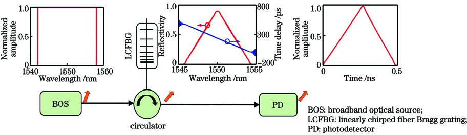
    Fig. 1. Schematic diagrams of the proposed arbitrary waveform generation system using a linearly chirped fiber Bragg grating
    Refractive index modulation and reflection spectra of grating varying with refractive index modulation scaling factor M1 when Rmax is set to be 0.9 or 0.95. (a) (c) Index modulations; (b) (d) reflection spectra
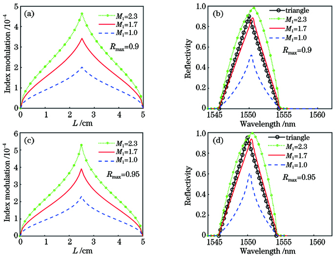
    Fig. 2. Refractive index modulation and reflection spectra of grating varying with refractive index modulation scaling factor M1 when Rmax is set to be 0.9 or 0.95. (a) (c) Index modulations; (b) (d) reflection spectra
    Influence of normalized spectral position of refractive index modulated vertex M2 on design error. (a) Index modulations; (b) reflection spectra
    Fig. 3. Influence of normalized spectral position of refractive index modulated vertex M2 on design error. (a) Index modulations; (b) reflection spectra
    Simulation results with different normalized spectral position of refractive index modulated vertex M2. (a)(c) Index modulations; (b)(d) reflection spectra
    Fig. 4. Simulation results with different normalized spectral position of refractive index modulated vertex M2. (a)(c) Index modulations; (b)(d) reflection spectra
    Simulation results with different grating lengths (L=1,2,3,4,5 cm). (a) Index modulations; (b) reflection spectra
    Fig. 5. Simulation results with different grating lengths (L=1,2,3,4,5 cm). (a) Index modulations; (b) reflection spectra
    Simulation results with different chirp coefficients (C=0.4,0.5,0.6,0.7,0.8 nm/cm ). (a) Index modulations; (b) reflection spectra
    Fig. 6. Simulation results with different chirp coefficients (C=0.4,0.5,0.6,0.7,0.8 nm/cm ). (a) Index modulations; (b) reflection spectra
    Simulation results with different index modulation errors. (a) Index modulations; (b) reflection spectra
    Fig. 7. Simulation results with different index modulation errors. (a) Index modulations; (b) reflection spectra
    Simulation results with different CFBG period errors. (a) Chirp coefficients; (b) reflection spectra
    Fig. 8. Simulation results with different CFBG period errors. (a) Chirp coefficients; (b) reflection spectra
    Simulation results of the CFBGs with trapezoidal-shaped spectra and rectangular-shaped spectra. (a) Index modulation for M2=1/3; (b) corresponding reflection spectrum for M2=1/3; (c) index modulations for M2=0, 1/20, 1/10, 1/5, and 2/5; (d) corresponding reflection spectra for M2=0, 1/20, 1/10, 1/5, and 2/5
    Fig. 9. Simulation results of the CFBGs with trapezoidal-shaped spectra and rectangular-shaped spectra. (a) Index modulation for M2=1/3; (b) corresponding reflection spectrum for M2=1/3; (c) index modulations for M2=0, 1/20, 1/10, 1/5, and 2/5; (d) corresponding reflection spectra for M2=0, 1/20, 1/10, 1/5, and 2/5
    Simulation results of the CFBG with Gaussian-shaped spectrum. (a) Index modulation; (b) reflection spectrum
    Fig. 10. Simulation results of the CFBG with Gaussian-shaped spectrum. (a) Index modulation; (b) reflection spectrum
    Simulation results of the CFBG with parabolic-shaped spectrum. (a) Index modulation; (b) reflection spectrum
    Fig. 11. Simulation results of the CFBG with parabolic-shaped spectrum. (a) Index modulation; (b) reflection spectrum
    Simulation setup of proposed arbitrary waveform generation system
    Fig. 12. Simulation setup of proposed arbitrary waveform generation system
    Simulation results of grating reflection spectra and time-domain pulses after frequency-to-time mapping under different number of segments W. (a) Triangular-shaped spectrum with W=100; (b) triangular pulses with W=100; (c) triangular-shaped spectrum with W=500; (d) triangular pulses with W=500
    Fig. 13. Simulation results of grating reflection spectra and time-domain pulses after frequency-to-time mapping under different number of segments W. (a) Triangular-shaped spectrum with W=100; (b) triangular pulses with W=100; (c) triangular-shaped spectrum with W=500; (d) triangular pulses with W=500
    Simulated reflection spectra with different shapes and the corresponding output pulses. (a)(c)(e)(g)(i) Designed reflection spectra; (b)(d)(f)(h)(j) output pulses after frequency-to-time mapping (black dashed lines are ideal pulses)
    Fig. 14. Simulated reflection spectra with different shapes and the corresponding output pulses. (a)(c)(e)(g)(i) Designed reflection spectra; (b)(d)(f)(h)(j) output pulses after frequency-to-time mapping (black dashed lines are ideal pulses)
    Simulation results with different grating lengths and pulse repetition rates. (a)(b) Parabolic-shaped pulse sequence after frequency-to-time mapping for grating length L=2.5 cm and 8 cm, respectively; (c)(d) parabolic-shaped pulse sequence after frequency-to-time mapping for repetition rate of 0.5 GHz and 2 GHz, respectively (black dashed lines are ideal pulses)
    Fig. 15. Simulation results with different grating lengths and pulse repetition rates. (a)(b) Parabolic-shaped pulse sequence after frequency-to-time mapping for grating length L=2.5 cm and 8 cm, respectively; (c)(d) parabolic-shaped pulse sequence after frequency-to-time mapping for repetition rate of 0.5 GHz and 2 GHz, respectively (black dashed lines are ideal pulses)
    Min Li, Hongqian Mu, Muguang Wang, Xinhang Wei, Xiangshuai Guan. Arbitrary Waveform Generation Based on Simple Design of Linearly Chirped Fiber Bragg Grating and Frequency-to-Time Mapping[J]. Chinese Journal of Lasers, 2021, 48(20): 2006001
    Download Citation