• Infrared and Laser Engineering
  • Vol. 51, Issue 4, 20210156 (2022)
Chaochao Zhang1、2, Jianbo Wang2, Cong Yin2, Baowu Zhang1, Ruonan Liu1、2, Lu Xi2, and Mengyao Li2、3
Author Affiliations
  • 1College of Metrology and Measurement Engineering, China Jiliang University, Hangzhou 310018, China
  • 2National Institute of Metrology, China, Beijing 100013, China
  • 3School of Optics and Photonics, Beijing Institute of Technology, Beijing 100081, China
  • show less
    DOI: 10.3788/IRLA20210156 Cite this Article
    Chaochao Zhang, Jianbo Wang, Cong Yin, Baowu Zhang, Ruonan Liu, Lu Xi, Mengyao Li. Research progress of optical phase-locked loop[J]. Infrared and Laser Engineering, 2022, 51(4): 20210156 Copy Citation Text show less
    Structural comparison of OPLL and PLL. (a) Diagram of PLL structure; (b) Diagram of OPLL structure
    Fig. 1. Structural comparison of OPLL and PLL. (a) Diagram of PLL structure; (b) Diagram of OPLL structure
    Complex frequency domain model of OPLL
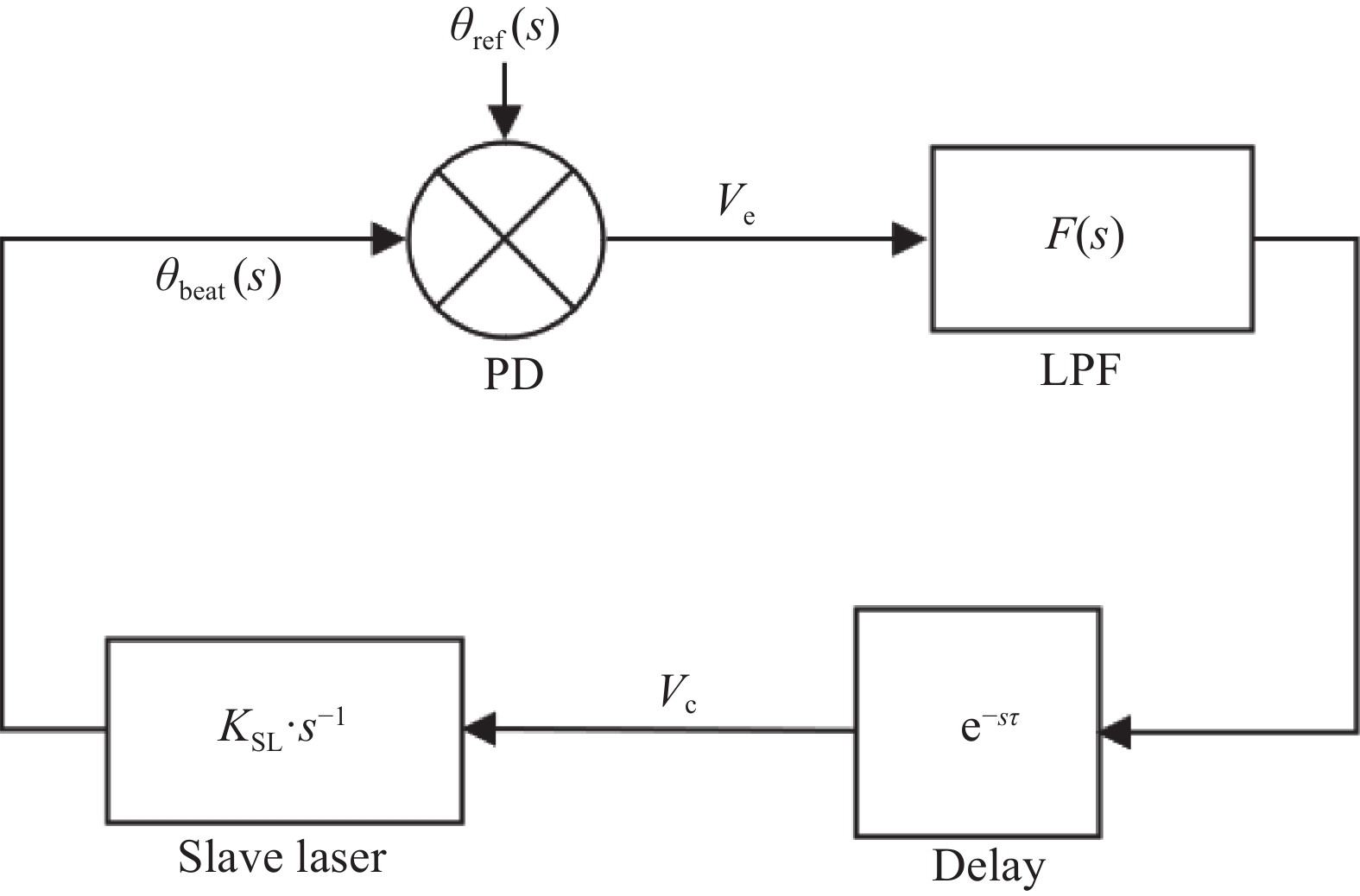
    Fig. 2. Complex frequency domain model of OPLL
    OPLL structure diagram using analog phase discrimination technology
    Fig. 3. OPLL structure diagram using analog phase discrimination technology
    OPLL structure diagram using digital phase discrimination technology
    Fig. 4. OPLL structure diagram using digital phase discrimination technology
    OPLL offset locking system based on FPGA
    Fig. 5. OPLL offset locking system based on FPGA
    Schematic diagram of all digital OPLL based on FPGA[28]
    Fig. 6. Schematic diagram of all digital OPLL based on FPGA[28]
    Integrated optical path for OPLL[38]
    Fig. 7. Integrated optical path for OPLL[38]
    Integrated OPLL offset locking system[39]
    Fig. 8. Integrated OPLL offset locking system[39]
    OPLL offset locking system for EIT experiment[25]
    Fig. 9. OPLL offset locking system for EIT experiment[25]
    OPLL offset locking system for atomic coherence experiments[24]
    Fig. 10. OPLL offset locking system for atomic coherence experiments[24]
    OPLL offset locking system for He-Ne laser source[23]
    Fig. 11. OPLL offset locking system for He-Ne laser source[23]
    OPLL offset locking system for ECDL[26]
    Fig. 12. OPLL offset locking system for ECDL[26]
    OPLL locking system for laser heterodyne interferometry source[45]
    Fig. 13. OPLL locking system for laser heterodyne interferometry source[45]
    OPLL system for coherent beam combining[46]
    Fig. 14. OPLL system for coherent beam combining[46]
    Improved OPLL system for coherent power combining[47]
    Fig. 15. Improved OPLL system for coherent power combining[47]
    TimeLaserOffset rangeType of phase discriminator Loop bandwidth LinewidthPhase noise level Phase error variance Optical structure
    MasterSlave
    1989[20]Nd:YAGNd:YAG6-34 GHzDBM-<1 mHz--Space light
    1992[42]DFBDFB3-18 GHzDBM180 MHz-<102 dBc/Hz0.04 rad2(1 GHz bandwidth) Space light
    1994[43]ECDLECDL<10 GHzDBM3.7 MHz50 kHz-<0.004 rad2Space light
    1999[44]DFBDFB7-14 GHzDBM70 MHz-−95 dBc/Hz (50 MHz offset) 0.05 rad2(1 GHz bandwidth) Space light
    2008[24]ECDLECDL250 kHz-20 GHzDBM+PFD-<10 Hz-<0.04 rad2Space light
    2008[25]ECDLECDL0.01-1.3 GHzPFD-500 kHz−153 dBc/Hz (10 kHz offset) <0.02 rad2Space light
    2012[39]-SG-DBR−9-7.5 GHzPFD400 MHz---Integrated optical circuit
    2012[27]DFBDS-DBR<40 GHzPFD100 kHz (open-loop unity-gain bandwidth) ---Space light
    2014[26]He-Ne Laser ECDL80 MHz-1.4 GHzPFD-3.2×10⁻⁹(stability) --Space light
    2017[17]OFCSG-DBR<26 GHzXOR phase discriminator--−80 dBc/Hz (200 Hz offset) 0.08 rad2(1 kHz-1 GHz bandwidth) Integrated optical circuit
    2018[41]ECDLDBR4-12 GHzanalog phase discriminator 100 MHz-−100 dBc/Hz >(10 kHz offset) 0.012 rad2Integrated optical circuit
    Table 1. Structure and key parameters of different OPLL offset locking systems
    Chaochao Zhang, Jianbo Wang, Cong Yin, Baowu Zhang, Ruonan Liu, Lu Xi, Mengyao Li. Research progress of optical phase-locked loop[J]. Infrared and Laser Engineering, 2022, 51(4): 20210156
    Download Citation