
Bo Yang, Hua Cheng, Shuqi Chen, Jianguo Tian. Multi-Dimensional Manipulation of Optical Field by Metasurfaces Based on Fourier Analysis[J]. Acta Optica Sinica, 2019, 39(1): 0126005
- Acta Optica Sinica
- Vol. 39, Issue 1, 0126005 (2019)
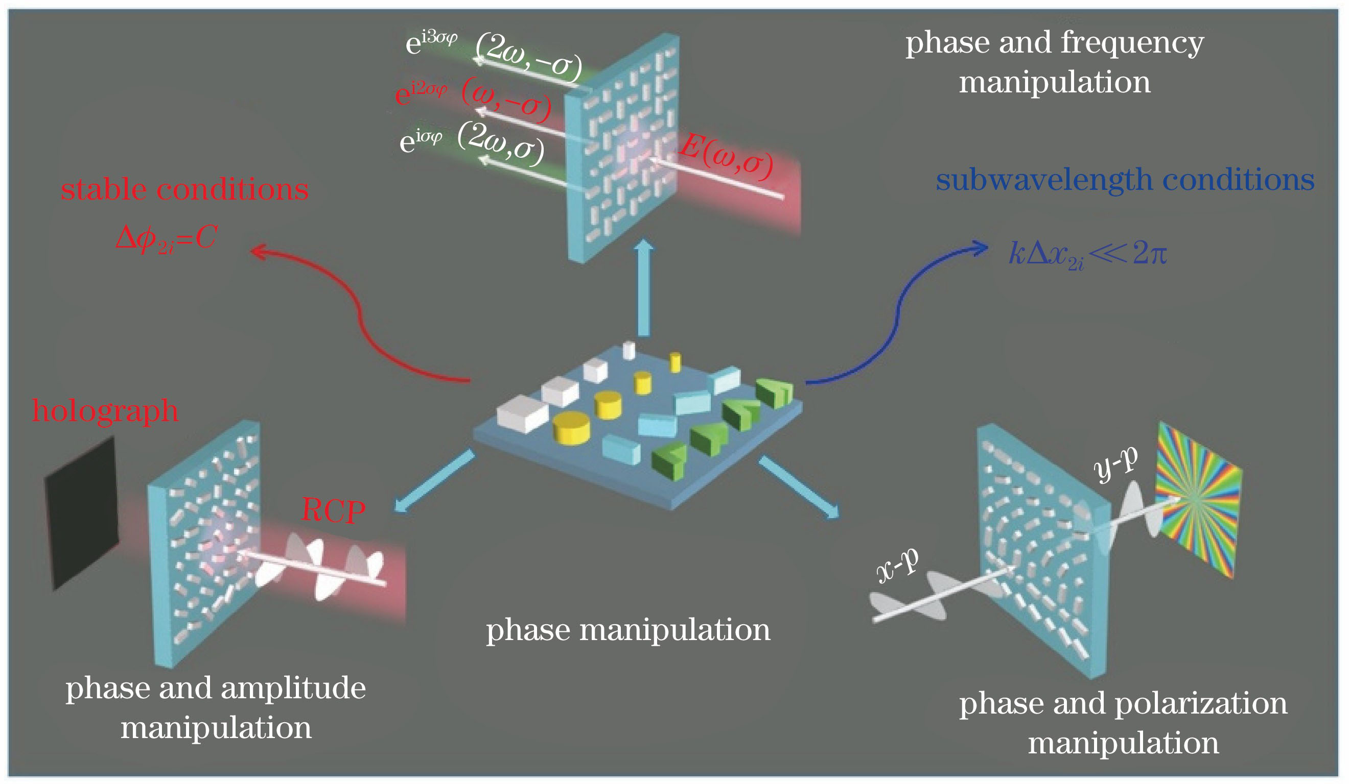
Fig. 1. Skeleton diagram of review
![Phase-gradient metasurfaces. (a) Metasurface with resonant phase[9]; (b) metasurface of geometric phase[43]; (c) metasurface of propagation phase[45]](/richHtml/gxxb/2019/39/1/0126005/img_2.jpg)
Fig. 2. Phase-gradient metasurfaces. (a) Metasurface with resonant phase[9]; (b) metasurface of geometric phase[43]; (c) metasurface of propagation phase[45]
Fig. 3. (a) Schematic of designed unit cells on metasurface[34]; (b) sphere of metaunit with polar angle of ?i/2 and azimuthal angle of kxi, where red-star-line shows equivalence of ?i/2+kxi=π[34]
Fig. 4. Metasurface of plasmonic half-wave plates[53]. (a) Schematic of PB metasurface; (b) arrangement of nanoantenna pairs of half-wave plates; (c) measured transmitted polarization angle and intensity
Fig. 5. Hologram of Huygen’s metasurface[54]. (a) SEM image; (b) dark-field microscope image; (c) theoretically holographic images at 1600 nm; (d) experimentally holographic images at 1600 nm
Fig. 6. Wide-angle Fourier lens[61]. (a) Schematic of Fourier lens; (b) phase difference and magnetic distribution of 8 dielectric silicon waveguides with incident light from -60° to 60°; (c) experimental intensity distribution of Fourier lens at xz plane
Fig. 7. Plasmonic metasurface with simultaneous control of phase and polarization[48]. (a) Schematic of upper and lower two-layer non-aligned structure; (b) simulated phase and amplitude curves of transmitted light of upper and lower non-aligned structures; (c) 26 nano-aperture pairs for full control of phase and polarization; (d) measured far-field intensity distributions of radially polarized beam
Fig. 8. Metasurface of dual-mode vector beam[69]. (a) Schematic of dual-layer metasurfaces; (b) phase and polarization distributions of transmitted circularly polarized light; (c) models of radially polarized vector beam; (d) models of azimuthally polarized vector beam; (e) models of dual-mode vector beam
Fig. 9. Dielectric metasurface with simultaneous control of phase and polarization[71]. (a) Schematic of metasurface; (b) schematic of polarization beamsplitter of x and y polarized light; (c) polarization-switchable phase hologram of x and y polarized light
Fig. 10. Metasurface with independent phase control at arbitrary orthogonal polarization state[72]. (a) Schematic of metasurface with arbitrary phase profile by combining geometric and propagation phase; (b) optical setup for chiral hologram designed by metasurface at wavelength of 532 nm; (c) different chiral holographic images by same metasurface under vertical polarization
Fig. 11. Broadband metasurface with simultaneous control of phase and amplitude. (a) Schematic of C-shape antenna metasurface[97]; (b) amplitude and phase curves of 3 diffraction orders at 0.63 THz[97]; (c) schematic of Huygens metasurface[98]; (d) phase variation of reflection coefficient S11 with different resonant lengths and rotation angles[98]
Fig. 12. Metasurface with multinanorods[99]. (a) Schematic of metasurface; (b) amplitudes of anomalous refraction for different nanorods; (c) plasmonic hybridization for multinanorods; (d) far-field normalized intensity curves of nanorods with different numbers
Fig. 13. Broadband holographic metasurface[109]. (a) Schematic of metasurface; (b) amplitude distribution and phase distribution of metasurface (left), and holographic images (right)
Fig. 14. Airy beam generated by metasurface with control of phase and amplitude[115]. (a) Schematic of plasmonic metasurface; (b) amplitude curves of gold nanorods with different lengths; (c) simulated electric field distributions of Airy beam without full amplitude modulation, amplitude modulation, and simplified amplitude modulation, respectively
Fig. 15. (a) Phase distribution of FWM field at surface exit[138]; (b) phases accumulated by different fields[138]; (c) SEM image and the measured focal field of 30 μm nonlinear metalens[138]; (d) SEM image and the measured focal field of 5 μm nonlinear metalens[138]
Fig. 16. Spin and wavelength multiplexed nonlinear holography[139]. (a) Linear and nonlinear geometric phases of metasurface; (b) linear and nonlinear holography imaging; (c) nonlinear holographic images
Fig. 17. Beam shaping of plasmonic nonlinear metasurface[143]. (a) Schematic of nonlinear metasurface; (b) SEM image of unit cells on metasurface; (c) vortex beam generated from nonlinear metasurface; (d) simulation and measurement images of SHG vortex beam in far field

Set citation alerts for the article
Please enter your email address
© Copyright 2018-2021 | Chinese Laser Press. All Rights Reserved 沪ICP备15018463号-20