
Guangze Peng, Wenjing Chen. Fringe Pattern Inpainting Based on Convolutional Neural Network Denoising Regularization[J]. Acta Optica Sinica, 2020, 40(18): 1810002
- Acta Optica Sinica
- Vol. 40, Issue 18, 1810002 (2020)
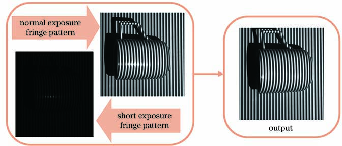
Fig. 1. Input-output fringes

Fig. 2. Architecture of denoising CNN
Fig. 3. Comparison of highlight areas determined by different methods. (a) Normal exposure time fringe pattern; (b) short exposure time fringe pattern; (c) modulation of Fig. 3 (a); (d) modulation of Fig. 3 (b); (e) result image of Fig. 3 (a) using Otsu threshold method; (f) result image of Fig. 3 (b) using Otsu threshold method
Fig. 4. Fusion process of iterative initial value
Fig. 5. Complete flow chart of fringe inpainting
Fig. 6. Results of inpainting. (a) Standard fringe pattern; (b) simulated fringe pattern with highlight region; (c) initial value of the iteration with Gaussian noise; (d) inpainting result of Ref. [19] method; (e) inpainting result of Ref. [20] method; (f) inpainting result of proposed method
Fig. 7. Experimental setup
Fig. 8. Comparison of inpainting results with different initial values. (a) Normal exposure time fringe pattern; (b) inpainting result of Fig. 8 (a); (c) initial image-fused by proposed method; (d) inpainting result of Fig. 8 (c)
Fig. 9. Fringe pattern inpainting results. (a) Original fringe pattern; (b) initial value for iteration; (c) inpainting result of Ref. [4] method; (d) inpainting result of Ref. [19] method; (e) inpainting result of Ref. [20] method; (f) inpainting result of proposed method
Fig. 10. Phase reconstruction results. (a) Result of Ref. [4] method; (b) result of Ref. [19] method; (c) result of Ref. [20] method; (d) result of iterative initial value; (e) result of proposed method
Fig. 11. Comparsion of gray distribution of fringe pattern under different exposure time. (a) Normal exposure time fringe pattern; (b) short exposure time fringe pattern; (c) inpainting result of proposed method; gray distribution of 170--370 columns in 256 row of (d) normal exposure time fringe pattern and (e) inpainting fringe pattern
Fig. 12. Comparison of reconstruction results. (a) Reconstruction result using normal exposure time fringe pattern; (b) reconstruction result using proposed method inpainting fringe pattern
|
Table 1. Comparison in execution time, PSNR, and RMSE of phase reconstruction with Ref. [19] method, Ref. [20] method, and proposed method

Set citation alerts for the article
Please enter your email address
© Copyright 2018-2021 | Chinese Laser Press. All Rights Reserved 沪ICP备15018463号-20