
Tao FENG, Wei-Qi JIN, Jun-Jie SI, Hai-Jun ZHANG. Optimal theoretical study of the pixel structure and spatio-temporal random noise of uncooled IRFPA[J]. Journal of Infrared and Millimeter Waves, 2020, 39(2): 142
- Journal of Infrared and Millimeter Waves
- Vol. 39, Issue 2, 142 (2020)
Abstract
Keywords
Introduction
Infrared thermal imaging technology is used to convert infrared radiation into electronic video images that can be observed by the human eye. The infrared focal plane array (IRFPA) is the core component of an infrared thermal imaging system. Its performance determines the performance of the system. IRFPA can be divided into two types according to the needs of the cooled device: cooled IRFPA and uncooled IRFPA. Cooled IRFPA has high sensitivity and a long detection range, but its structure is complex and expensive. It is usually used in high-end military equipment and space remote sensing. Uncooled IRFPA can work at room temperature without a cooled device, however the sensitivity of uncooled IRFPA is lower than that of cooled IRFPA. Uncooled IRFPA has many advantages, such as fast start-up, low power consumption, small size, light weight, long life, low cost and so on [
In recent years, several technologies in uncooled IRFPA, such as the packaging technology, detector materials, microbridge structure, optical resonator, and readout circuit have been improved dramatically [
1 Pixel structure and noise characteristics of uncooled IRFPA
1.1 Pixel structure of uncooled IRFPA
There are several types of uncooled IRFPA, including thermoelectric stack / thermocouple, pyroelectric, optical mechanical, microbolometer and so on. The microbolometer type has experienced the most rapid development, and it is far superior to other kinds of uncooled IRFPA in its application scope and quantities produced [
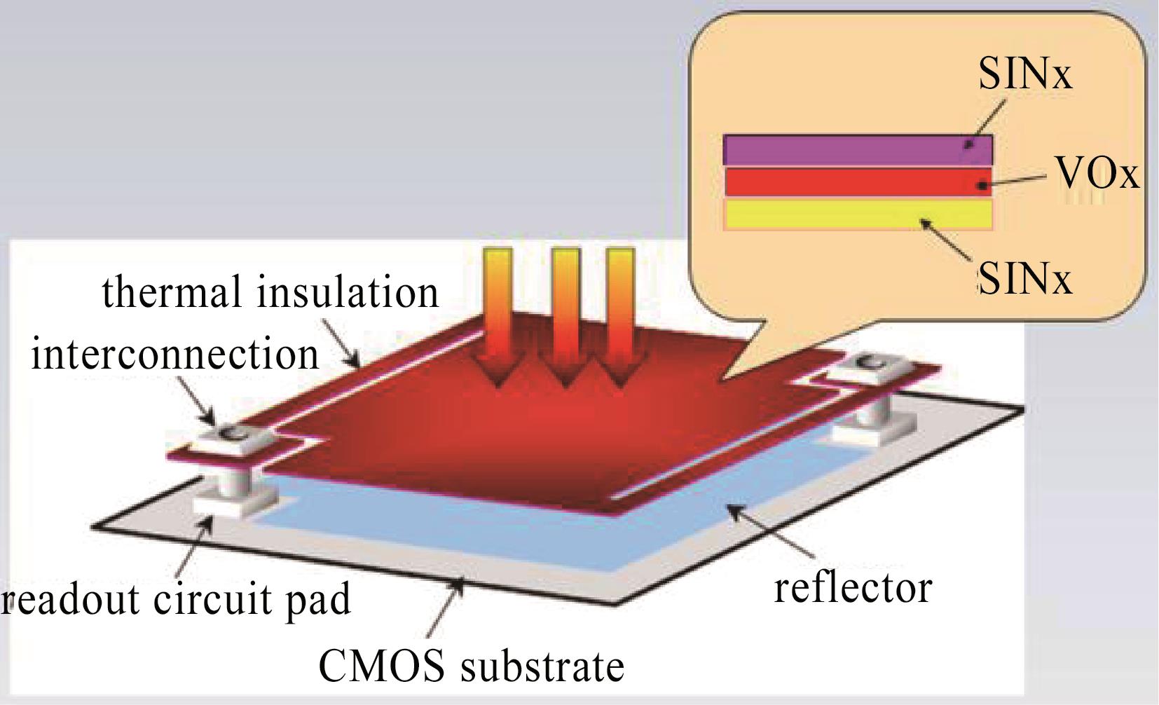
![]()
Figure 1.Structure of the microbolometer [
Optimization of the microbolometer is usually done in two ways: material selection and pixel structure design. The material of the heat absorption layer is required to have a high heat absorption capacity. At present, silicon nitride (SiNx) material is usually used to make the heat absorption layer, which is made in a "sandwich" structure (see
![]()
Figure 2.Pixel MEMS architecture (a) single layer,(b) double layers
The difference between the double-layer structure and single-layer structure is mainly expressed on the membrane and leg. The effect of the membrane is to absorb infrared radiation and convert heat into the change in value of the pixel resistance. The area of the membrane with infrared absorption ability is called the effective area of the pixel. The larger the effective area, the stronger the absorption ability for infrared radiation. For a single-layer structure, the total area of the pixel is composed of the membrane and leg. Since the leg has almost no infrared absorption ability, the effective area of the pixel is only the membrane part. The leg and membrane of the double-layer structure belong to different layers, and the effective area is almost the same as that of the whole pixel, that is, the double-layer structure usually has a larger effective area than the single-layer structure[
It is in the heat exchange process that the membrane absorbs heat, which results in a change in the resistance of the heat sensitive layer. Therefore, the membrane should have enough thermal capacity to achieve high heat transfer efficiency. The thermal capacity of the membrane is determined by the thermal conductivity between the membrane and the surrounding environment. The thermal conductivity of the membrane mainly includes the contact thermal conductivity between the membrane and the substrate, the convection thermal conductivity between the membrane and the surrounding air, the radiative thermal conductivity of the membrane to the environment, and so on. The pixel of uncooled IRFPA is in a vacuum package and works at room temperature, so the thermal conductivity of the membrane is mainly from the leg, which plays on a mechanical connection between the membrane and the substrate [
In conclusion, the two-layer structure of uncooled IRFPA pixels is different from the single-layer structure in the effective area of the pixel and thermal conductivity of the leg, which affects the performance of uncooled IRFPA.
1.2 Noise characteristics of uncooled IRFPA
The United States Army's Night Vision and Electronic Sensors Directorate (NVESD) presented a three-dimensional noise model [
in the Eq. 1, is the function of the three variables in time, vertical direction and horizontal direction[
Among them, T represents the time or frame sequence, and H and V represent spatial dimensions. Seven noise components are described as shown in
| Noise Component | Description | Explanation |
|---|---|---|
| σT | Frame-to-frame noise | Frame average that fluctuates over time. |
| σTV | Temporal row noise | The part of the row average that fluctuates over time. |
| σTH | Temporal column noise | The part of the column average that fluctuates over time. |
| σTVH | Spatial-temporal random noise | The part of each pixel output that fluctuates randomly over time. |
| σV | Spatial row noise | The part of the row average that differs from the spatial distribution. |
| σH | Spatial column noise | The part of the column average that differs from the spatial distribution. |
| σVH | Spatial random noise | The part of each pixel output that differs from the spatial distribution. |
Table 1. Description of seven noise components
The more significant noise components of the seven noise components are the spatio-temporal random noise σTVH, the spatial random noise σVH, the temporal row noise σTV, and the spatial column noise σH. The spatial random noise σVH only changes in the direction of row and column, but does not change with time, which affects the output value of different coordinate pixels of IRFPA. It also known as fixed pattern noise, which comes from the difference of signal response between different pixels. The temporal row noise σTV refers to the fluctuation of the average value of each row with time between frames, also known as time horizontal stripe noise, which mainly comes from the low frequency noise on the bias voltage of detector. The spatial column noise σH refers to the fixed non-uniformity between columns, also known as spatial vertical striped noise, which mainly comes from the individual differences between the elements (including blind pixels, integral capacitors, integrators, etc.) shared by each column in FPA.
Because uncooled IRFPA is a staring imaging device, the most important of the seven noise components is the spatio-temporal random noise σTVH[
Uncooled IRFPA, as a microbolometer, converts the thermal radiation signal into an electrical signal by applying a bias voltage pulse on a pixel thermistor, so the thermal noise and flicker noise are the main parts of σTVH[
![]()
Figure 3.Noise power density of a semiconductor resistor
2 Spatio-temporal random noise model of uncooled IRFPA
2.1 NETD of spatio-temporal random noise
The noise of the IRFPA directly affects the performance of the imaging system. The noise equivalent temperature difference (NETD) is a parameter to evaluate the performance of the IRFPA, which combines the noise level and the signal response ability. Because of its clear definition and ease of testing, it has been widely used. The NETD formula for uncooled IRFPA is [
where is the noise voltage of IRFPA and is the response rate of the signal voltage.
The NETD model of spatio-temporal random noise can represent the effect of spatio-temporal random noise on the performance of the system.
where is the spatio-temporal random noise voltage of IRFPA.
Since spatio-temporal random noise mainly comes from thermal noise and flicker noise, the following formula is approximate:
where is the square root of the IRFPA's thermal noise voltage, and is the square root of the IRFPA's flicker noise voltage.
The thermal noise equivalent temperature difference of the IRFPA is defined as, and the flicker noise equivalent temperature difference of the IRFPA is defined as, which is as follows:
According to Eqs. 4-7, the following formula is obtained:
2.2 Modeling of the relationship between pixel structure parameters and spatio-temporal random noise NETD
![]()
Figure 4.Signal transfer and readout IC principle diagram of uncooled IRFPA
According to
here, is the reference voltage of the integrator; is the integration current; is the integration time; is the integration capacitance; is the bias voltage applied to ; and is the bias voltage applied to .
For the uncooled IRFPA under certain working conditions, , , , , , and are independent of the external thermal radiation and can be considered as constants. is a variable that changes with external thermal radiation, and causes the change of output signal , so is a function of .
The voltage response rate of the pixel can be obtained by calculating the derivative of the output signal voltage to the target temperature:
where is the target temperature. The target temperature causes the change of pixel temperature through thermal radiation, the change of pixel temperature causes the change of pixel resistance value , and finally the change of pixel resistance value leads to the change in pixel output voltage . Thus, in Eq. 10, the -to- derivation can be converted into a combination of -to- derivation, -to- derivation, and -to- derivation:
here, is the TCR of the pixel ().
The thermal noise of an IRFPA pixel is related to the pixel temperature, pixel resistance, bandwidth, and so on. It is expressed as [
here, is thermal noise, is the Boltzmann constant; and is the bandwidth of the test system.
By Eqs. 11-12, the thermal noise of the IRFPA pixel is:
The flicker noise of the IRFPA pixel is related to the pixel volume, the current flowing through the pixel, the working frequency, and so on. It is expressed as [
here, is flicker noise; is the current flowing through the pixel; is the coefficient of flicker noise; is the pixel volume; and and are the lower cut-off frequency and the upper cut-off frequency of the measurement frequency band, respectively.
By Eqs 11-14, the flicker noise of the IRFPA pixel can be obtained:
It can be noted that both Eq. 13 and Eq. 15 have the derivation of the pixel temperature of the target temperature , and the relation between it and the pixel parameters is [
here, is the thermal conductance of the pixel; is the effective area of the pixel; is the infrared absorption rate of the pixel; is the F number of optics; is the radiance of the target, and the higher the target temperature, the greater the value of .
Equation 16 is substituted into Eq. 13 and Eq. 15. and are obtained as follows:
In the formulas, and are used to replace other parameters independent of and , and the simplified formula can be obtained. Most of the parameters replaced by and are mainly related to pixel material and working conditions, but have a weak relationship with pixel structure (effective area and thermal conductance of the pixel). Individual parameters, such as pixel volume , are usually related to pixel effective area , but in order to simplify the analysis, the pixel volume can be kept unchanged when the pixel effective area is changed, such as reducing the pixel thickness while increasing the pixel effective area, so that the pixel volume is also independent of the pixel effective area .
Equation 19 can be obtained by Eqs. 8, 17-18:
It can be seen that the spatio-temporal random noise of the pixel is inversely proportional to the effective area of the pixel and is proportional to the thermal conductivity . As mentioned earlier, the parameters and are mainly determined by the MEMS structure of the pixel, and the relationship between the pixel structure of uncooled IRFPA and the spatio-temporal random noise can be studied from the two parameters.
3 Experimental verification of the relationship between pixel structure and spatio-temporal random noise
According to the pixel structure and spatio-temporal random noise model of uncooled IRFPA, a typical single-layer uncooled IRFPA is selected to optimize the pixel structure design, and a double-layer pixel structure uncooled IRFPA is developed. The spatio-temporal random noise of the two types of pixel structure are compared to verify the validity of the theoretical model.
3.1 Optimization of uncooled IRFPA pixel structure
GWIR0202X1A is a single-layer uncooled IRFPA product produced by Chinese North Guangwei Technology Inc., as shown in
![]()
Figure 5.Uncooled IRFPA GWIR0202X1A
Based on GWIR0202X1A, we changed the pixel structure to a double-layer structure, and the other designs such as readout circuit, package and so on, remained the same. The new double-layer structure uncooled IRFPA is called GWIR0202X1A(D). The improvement in performance caused by the change in pixel structure is mainly as follows:
(1)Increase in the effective area of pixel
As mentioned above, the effective area and fill factor of the double-layer structure are larger than that of the single-layer structure. According to the design, the effective area of GWIR0202X1A is about 450 μm2, and the fill factor is about 72%. The effective area of GWIR0202X1A(D) is about 531 μm2, and the fill factor is about 85%.
(2)Reduction of the thermal conductivity of the pixel leg
The formula for calculating the thermal conductivity of the pixel leg is as follows:
here, is the thermal conductivity of the leg, is the cross-sectional area of the leg, is the length of the leg, and the coefficient 2 is because a pixel membrane is supported by two legs.
Without changing the material of the leg, a lower thermal conductivity can be obtained by increasing the leg length or decreasing the leg cross-sectional area , but increasing the length or decreasing the cross-sectional area of the leg decreases the mechanical strength of the leg. Compared with GWIR0202X1A, GWIR0202 X1A(D) not only increases the leg length but also increases the leg cross-sectional area , while reducing the / value, thus reducing the thermal conductivity of the leg, and it maintains sufficient mechanical strength. According to the design, the thermal conductivity of the double-layer structure leg can be reduced to about 80% of that in the single-story structure.
(3)Comprehensive improvement
According to the spatio-temporal random noise model and the relationship between the two pixel structure parameters, the following results can be obtained:
That is, the double-layer pixel structure can be reduced to about 67.8% of the single-layer pixel structure . This amplitude of the noise reduction will significantly improve the performance of the IRFPA.
3.2 Experimental verification of the relationship between pixel structure and spatio-temporal random noise
Thirty pieces of single-layer GWIR0202X1A and thirty pieces of double-layer GWIR0202X1A(D) were selected for experimental verification. According to the three-dimensional noise model, the NETD of each noise component and the proportion of the noise components in the total noise energy were obtained,and then calculate the mean value of the samples.
The 3D noise components of single-layer and double-layer IRFPA are shown in
| 3D noise component | σT | σTH | σTV | σTVH | σH | σV | σVH | σSYS | |
|---|---|---|---|---|---|---|---|---|---|
| Single-layer pixel | The mean of the NETD component/mK | 5.0 | 15.5 | 4.9 | 30.9 | 3.4 | 7.2 | 22.8 | 42.7 |
| Percentage of noise component to total noise/( | 1.3% | 13.2% | 1.3% | 52.3% | 0.6% | 2.8% | 28.5% | 100% | |
| Double-layer pixel | The mean of the NETD component/mK | 3.5 | 14.6 | 4.3 | 21.6 | 3.2 | 5.8 | 20.9 | 34.5 |
| Percentage of noise component to total noise/( | 1.0% | 17.9% | 1.5% | 39.2% | 0.9% | 2.8% | 36.7% | 100% |
Table 2. 3D Noise test results of single-layer and two-layer uncooled IRFPA
Due to the reduction of the largest noise component σTVH in uncooled IRFPA noise, the total NETD of IRFPA decreases from 42.7 mK of the single-layer structure to 34.5 mK of the double-layer structure, which effectively improves the performance of the IRFPA. At the same time, it is noted that with the decrease in the spatio-temporal random noise component σTVH, the proportion of the spatial random noise component σVH has also increased from 28.5% to 36.7% in the double-layer structure IRFPA. The next step of the study will focus on the spatial random noise component σVH to explore ways to further improve the uncooled IRFPA performance.
4 Conclusions
Microbolometer uncooled IRFPA is a widely used infrared focal plane detector. The main technical development direction to improve the performance of the uncooled IRFPA is to reduce the noise of the detector. In this paper, a single-layer structure and double-layer structure for uncooled IRFPA pixel are introduced. The effective area of the pixel, the thermal conductivity of the leg and the influence of the largest spatio-temporal random noise component in the three-dimensional noise model are analyzed. The mathematical model of spatio-temporal random noise of uncooled IRFPA is derived. It is pointed out that the effective area of the pixel and the thermal conductivity of the leg are two important parameters in the model. The validity of the model is verified by the experimental testing of single-layer and double-layer uncooled IRFPA.
The uncooled IRFPA of the double-layer structure effectively reduces the spatio-temporal random noise component, which gradually approaches the level of the spatial random noise component. To continue to reduce the noise of uncooled IRFPA, it is necessary to explore the factors of influence given by more noise components, and carry out research on the theory, design and manufacturing process.
References
[3] A Rogalski. Next decade in infrared detectors. Electro-Optical and Infrared Systems: Technology and Applications XIV, 10433, 10433L(2017).
[4] C Li, C J Han, G Skidmore. Overview of DRS uncooled VOx infrared detector development. Optical Engineering, 50, 061017(2011).
[5] D Murphy, M Ray, J Wyles. 640×512 17 µm microbolometer FPA and sensor development. Infrared Technology and Applications XXXIII, 65421Z, 65421Z(2007).
[6] S Tohyama, T Sasaki, T Endoh. Uncooled infrared detectors toward smaller pixel pitch with newly proposed pixel structure. Optical Engineering, 52, 123105(2013).
[8] P Wang, S Chen, X Gan. High sensitivity 17µm pixel pitch 640 × 512 uncooled infrared focal plane arrays based on amorphous vanadium oxide thin films. IEEE Electron Device Letters, 36, 923-925(2015).
[10] F Niklaus, C Vieider, H Jakobsen. MEMS-based uncooled infrared bolometer arrays-review. MEMS/MOEMS Technologies and Applications III, 6836, 68360D(2007).
[11] J D'Agostino, C Webb. 3-D analysis framework and measurement methodology for imaging system noise. Testing II, 1488, 110-121(1991).
[14] S Sousk, P O’Shea, V Hodgkin. Measurement of uncooled thermal imager noise. Testing XVI, 5784, 301-308(2005).
[15] L Scott, J D'Agostino. NVEOD FLIR92 thermal imaging systems performance model. Infrared Imaging Systems, 1689, 194-203(1992).
[16] X N Yu, L G Nie, T L Hu. Model building and measurement of the temporal noise for thermal infrared imager. Ninth International Symposium on Laser Metrology, 7155, 71551C(2008).
[18] A Rogalski. Infraed detectors(2014).
[19] P W Kruse, D D Skatrud. Uncooled infrared imaging arrays and systems(1997).
[20] H Budzier, G Gerlach. Thermal infrared sensors: theory, optimisation and practice(2011).

Set citation alerts for the article
Please enter your email address
© Copyright 2018-2021 | Chinese Laser Press. All Rights Reserved 沪ICP备15018463号-20